EP2362160A2 - Dispositif de support pour modules photovoltaïques - Google Patents
Dispositif de support pour modules photovoltaïques Download PDFInfo
- Publication number
- EP2362160A2 EP2362160A2 EP10015860A EP10015860A EP2362160A2 EP 2362160 A2 EP2362160 A2 EP 2362160A2 EP 10015860 A EP10015860 A EP 10015860A EP 10015860 A EP10015860 A EP 10015860A EP 2362160 A2 EP2362160 A2 EP 2362160A2
- Authority
- EP
- European Patent Office
- Prior art keywords
- spar
- carrier
- support
- fastening
- hollow profile
- Prior art date
- Legal status (The legal status is an assumption and is not a legal conclusion. Google has not performed a legal analysis and makes no representation as to the accuracy of the status listed.)
- Withdrawn
Links
- 238000004873 anchoring Methods 0.000 claims abstract description 4
- 229910000831 Steel Inorganic materials 0.000 claims description 2
- XAGFODPZIPBFFR-UHFFFAOYSA-N aluminium Chemical compound [Al] XAGFODPZIPBFFR-UHFFFAOYSA-N 0.000 claims description 2
- 229910052782 aluminium Inorganic materials 0.000 claims description 2
- 239000010959 steel Substances 0.000 claims description 2
- 239000007787 solid Substances 0.000 description 2
- 230000001419 dependent effect Effects 0.000 description 1
- 238000004519 manufacturing process Methods 0.000 description 1
- 239000002994 raw material Substances 0.000 description 1
- 229910001220 stainless steel Inorganic materials 0.000 description 1
- 239000010935 stainless steel Substances 0.000 description 1
Images

Classifications
-
- H—ELECTRICITY
- H02—GENERATION; CONVERSION OR DISTRIBUTION OF ELECTRIC POWER
- H02S—GENERATION OF ELECTRIC POWER BY CONVERSION OF INFRARED RADIATION, VISIBLE LIGHT OR ULTRAVIOLET LIGHT, e.g. USING PHOTOVOLTAIC [PV] MODULES
- H02S20/00—Supporting structures for PV modules
- H02S20/10—Supporting structures directly fixed to the ground
-
- F—MECHANICAL ENGINEERING; LIGHTING; HEATING; WEAPONS; BLASTING
- F24—HEATING; RANGES; VENTILATING
- F24S—SOLAR HEAT COLLECTORS; SOLAR HEAT SYSTEMS
- F24S25/00—Arrangement of stationary mountings or supports for solar heat collector modules
- F24S25/10—Arrangement of stationary mountings or supports for solar heat collector modules extending in directions away from a supporting surface
- F24S25/12—Arrangement of stationary mountings or supports for solar heat collector modules extending in directions away from a supporting surface using posts in combination with upper profiles
-
- F—MECHANICAL ENGINEERING; LIGHTING; HEATING; WEAPONS; BLASTING
- F24—HEATING; RANGES; VENTILATING
- F24S—SOLAR HEAT COLLECTORS; SOLAR HEAT SYSTEMS
- F24S25/00—Arrangement of stationary mountings or supports for solar heat collector modules
- F24S25/60—Fixation means, e.g. fasteners, specially adapted for supporting solar heat collector modules
- F24S25/61—Fixation means, e.g. fasteners, specially adapted for supporting solar heat collector modules for fixing to the ground or to building structures
- F24S25/617—Elements driven into the ground, e.g. anchor-piles; Foundations for supporting elements; Connectors for connecting supporting structures to the ground or to flat horizontal surfaces
-
- F—MECHANICAL ENGINEERING; LIGHTING; HEATING; WEAPONS; BLASTING
- F24—HEATING; RANGES; VENTILATING
- F24S—SOLAR HEAT COLLECTORS; SOLAR HEAT SYSTEMS
- F24S25/00—Arrangement of stationary mountings or supports for solar heat collector modules
- F24S25/60—Fixation means, e.g. fasteners, specially adapted for supporting solar heat collector modules
- F24S25/63—Fixation means, e.g. fasteners, specially adapted for supporting solar heat collector modules for fixing modules or their peripheral frames to supporting elements
- F24S25/632—Side connectors; Base connectors
-
- F—MECHANICAL ENGINEERING; LIGHTING; HEATING; WEAPONS; BLASTING
- F24—HEATING; RANGES; VENTILATING
- F24S—SOLAR HEAT COLLECTORS; SOLAR HEAT SYSTEMS
- F24S25/00—Arrangement of stationary mountings or supports for solar heat collector modules
- F24S25/60—Fixation means, e.g. fasteners, specially adapted for supporting solar heat collector modules
- F24S25/65—Fixation means, e.g. fasteners, specially adapted for supporting solar heat collector modules for coupling adjacent supporting elements, e.g. for connecting profiles together
-
- F—MECHANICAL ENGINEERING; LIGHTING; HEATING; WEAPONS; BLASTING
- F24—HEATING; RANGES; VENTILATING
- F24S—SOLAR HEAT COLLECTORS; SOLAR HEAT SYSTEMS
- F24S25/00—Arrangement of stationary mountings or supports for solar heat collector modules
- F24S25/70—Arrangement of stationary mountings or supports for solar heat collector modules with means for adjusting the final position or orientation of supporting elements in relation to each other or to a mounting surface; with means for compensating mounting tolerances
-
- F—MECHANICAL ENGINEERING; LIGHTING; HEATING; WEAPONS; BLASTING
- F24—HEATING; RANGES; VENTILATING
- F24S—SOLAR HEAT COLLECTORS; SOLAR HEAT SYSTEMS
- F24S25/00—Arrangement of stationary mountings or supports for solar heat collector modules
- F24S2025/80—Special profiles
- F24S2025/804—U-, C- or O-shaped; Hat profiles
-
- Y—GENERAL TAGGING OF NEW TECHNOLOGICAL DEVELOPMENTS; GENERAL TAGGING OF CROSS-SECTIONAL TECHNOLOGIES SPANNING OVER SEVERAL SECTIONS OF THE IPC; TECHNICAL SUBJECTS COVERED BY FORMER USPC CROSS-REFERENCE ART COLLECTIONS [XRACs] AND DIGESTS
- Y02—TECHNOLOGIES OR APPLICATIONS FOR MITIGATION OR ADAPTATION AGAINST CLIMATE CHANGE
- Y02E—REDUCTION OF GREENHOUSE GAS [GHG] EMISSIONS, RELATED TO ENERGY GENERATION, TRANSMISSION OR DISTRIBUTION
- Y02E10/00—Energy generation through renewable energy sources
- Y02E10/40—Solar thermal energy, e.g. solar towers
- Y02E10/47—Mountings or tracking
-
- Y—GENERAL TAGGING OF NEW TECHNOLOGICAL DEVELOPMENTS; GENERAL TAGGING OF CROSS-SECTIONAL TECHNOLOGIES SPANNING OVER SEVERAL SECTIONS OF THE IPC; TECHNICAL SUBJECTS COVERED BY FORMER USPC CROSS-REFERENCE ART COLLECTIONS [XRACs] AND DIGESTS
- Y02—TECHNOLOGIES OR APPLICATIONS FOR MITIGATION OR ADAPTATION AGAINST CLIMATE CHANGE
- Y02E—REDUCTION OF GREENHOUSE GAS [GHG] EMISSIONS, RELATED TO ENERGY GENERATION, TRANSMISSION OR DISTRIBUTION
- Y02E10/00—Energy generation through renewable energy sources
- Y02E10/50—Photovoltaic [PV] energy
Definitions
- the invention relates to a stator device for mounting photovoltaic modules, with a stand part for a solid anchoring in the ground, a support part for placing photovoltaic modules and a fixing part for fixing the photovoltaic modules to the support part.
- Stand devices of the type mentioned above are used in the prior art to install photovoltaic modules not in the range of roofs, but a large area near the ground.
- the known devices have the disadvantage that they are complicated in manufacturing and therefore expensive in poor dimensional stability.
- the object of the invention is therefore to provide a stand device that is durable and robust and is inexpensive to produce.
- stator part includes at least one formed as a hollow profile carrier spar having in the region of the modules near ends each have a passage opening for receiving a support member forming the support member, wherein the Mounting part includes at least one perpendicular to the support rail arranged fastening strip, which is fastened by means of a fastener releasably fixed to the support spar.
- stator device in the stator device according to the invention is characterized by the combination of features that the stator part includes at least one formed as a hollow profile carrier spar having in the region of the modules near ends each have a passage opening for receiving a support member forming the support member, wherein the fastening part at least one perpendicular to
- the support rail arranged fastening strip which is fastened by means of a fastener detachably fixed to the support spar, ensures that all components required for the preparation are available as raw material as high-quality mass-produced, where the effort in the context of further processing to form the specific invention embossed components is minimized.
- stator device according to the invention is robust, durable and dimensionally stable.
- a hollow profile to be designed as a tube having a substantially rectangular cross-section, that is to say as a square profile.
- a support spar is preferably also designed as a four-edged hollow profile.
- the upright part preferably has at least two carrier bars formed as a hollow profile.
- the fastening element is designed for fastening a fastening strip on a support member as a clamping element formed in the hollow profile, which in the region of its lower surface and side walls each having a recess into which a projection formed on a mounting strut intervenes.
- a clamping element may have at least in the region of its surface a passage opening through which a screw can be inserted, which is anchored in a slot of a supporting spar.
- a photovoltaic module is releasably secured by means of a further fastening element to a fastening strip, wherein the further fastening element also has a recess, in which engages a trained on a mounting bar projection.
- a passage opening formed on a carrier spar for receiving a supporting spar is designed as slots formed in two opposing side walls of the carrier spar, wherein a first elongated hole is offset in height from a second slot to a positioning to ensure a supporting beam at an angle different from 90 ° with respect to the support beam.
- a support spar and a carrier spar can preferably be firmly connected to one another by means of a locking strut ensuring a stable position of the supporting spar, wherein an angle at which a supporting spar is fastened to the carrier spar can be predetermined over the length or the point of attachment of the arresting strut.
- a support beam is attached to a support element anchored as a double T-beam, anchored in the ground, wherein slots are provided in the region of a distal end of a support Holmes open down oblong holes in which is a central part of a double-T-carrier inserted and fixed by means of screws.
- Beam spar, support spar and mounting strips are preferably made of steel or aluminum.
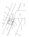
- the in the FIGS. 1 to 3 illustrated stand apparatus 100 for mounting photovoltaic modules according to the invention comprises a stand part for a solid anchoring in the ground, a support part for placing photovoltaic modules and a fixing part for fixing the photovoltaic modules to the support part.
- the upright part contains two carrier bars 110 designed as a hollow profile, which have a passage opening 111 for receiving a support spar 120 in the vicinity of the modules 150, wherein two parallel aligned, opposing supporting bars 120 form the carrier part.
- the fastening part contains a plurality of fastening strips 130 which are arranged at right angles to the support struts 120 and which are fastened in each case in a releasably fixed manner to a support strut 120 by means of a fastening element 140.
- Support beams 120 and support bars 110 are each formed as a square profile having pipe.
- a fastening strip 130 is formed substantially as a C-profile.
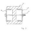
- the fastening element 140 for fastening a fastening strip 130 to a support spar 120 is designed as a clamping element 140 formed in the hollow profile, which has a recess 143 in the region of its lower surface 141 and side walls 142, into which a projection 131 formed on a fastening strut 130 engages.
- a clamping element 140 has, at least in the region of its surface 144, a passage opening through which a screw can be inserted, which is anchored in a slot of a supporting spar 120.
- a photovoltaic module 150 is releasably secured by means of a further fastening element 160 to a fastening strip 130, wherein the further fastening element 160 likewise has a recess 161 into which engages a projection 132 formed on a fastening strip 130.
- a formed on a support beam 110 passage opening 111 for receiving a support beam 120 is designed as formed in two opposing side walls of the support beam 110 slots, a first slot is offset in height relative to a second slot arranged to a positioning of a support beam 120 in one of 90 ° ensure different angles with respect to the carrier spar 110.
- a support beam 120 and a support beam 110 are fixedly connected to one another by means of a locking strut 170 ensuring a stable position of the support strut 120, wherein an angle at which a support strut 120 is fastened to the support strut 110 can be predetermined over the length or attachment point of the arresting strut 170 ,
- a carrier spar 110 is fastened to a carrier element 112 embodied as a double-T carrier, wherein in the area of a support spar 120 the distal end of a carrier spar 110 is provided open slots which are open at the bottom and into which a central part of a double T. Carrier insertable and can be fixed by means of screws 113.
- Carrier spar 110, support spar 120 and fastening strips 130 are made of stainless steel.
Landscapes
- Engineering & Computer Science (AREA)
- Physics & Mathematics (AREA)
- Life Sciences & Earth Sciences (AREA)
- Sustainable Development (AREA)
- Sustainable Energy (AREA)
- Thermal Sciences (AREA)
- Chemical & Material Sciences (AREA)
- Combustion & Propulsion (AREA)
- Mechanical Engineering (AREA)
- General Engineering & Computer Science (AREA)
- Photovoltaic Devices (AREA)
- Roof Covering Using Slabs Or Stiff Sheets (AREA)
Applications Claiming Priority (1)
| Application Number | Priority Date | Filing Date | Title |
|---|---|---|---|
| DE202010002830U DE202010002830U1 (de) | 2010-02-25 | 2010-02-25 | Ständer-Vorrichtung für Photovoltaik-Module |
Publications (2)
| Publication Number | Publication Date |
|---|---|
| EP2362160A2 true EP2362160A2 (fr) | 2011-08-31 |
| EP2362160A3 EP2362160A3 (fr) | 2014-09-17 |
Family
ID=42235061
Family Applications (1)
| Application Number | Title | Priority Date | Filing Date |
|---|---|---|---|
| EP10015860.9A Withdrawn EP2362160A3 (fr) | 2010-02-25 | 2010-12-21 | Dispositif de support pour modules photovoltaïques |
Country Status (2)
| Country | Link |
|---|---|
| EP (1) | EP2362160A3 (fr) |
| DE (1) | DE202010002830U1 (fr) |
Families Citing this family (4)
| Publication number | Priority date | Publication date | Assignee | Title |
|---|---|---|---|---|
| DE102012209162A1 (de) * | 2012-05-31 | 2013-12-05 | Hilti Aktiengesellschaft | Tragkonstruktion für Solarpaneele |
| DE202012011155U1 (de) * | 2012-09-25 | 2014-01-08 | Habdank Pv-Montagesysteme Gmbh & Co. Kg | Tragkonstruktion für Solarmodule |
| CN105042911B (zh) * | 2015-08-07 | 2016-11-30 | 山东省农业科学院 | 一种太阳能集热装置 |
| DE202023000646U1 (de) | 2023-03-22 | 2023-08-04 | Sebastian Weber | Hochbeet mit Solarpanel als Überdachung |
Family Cites Families (7)
| Publication number | Priority date | Publication date | Assignee | Title |
|---|---|---|---|---|
| DE9310063U1 (de) * | 1993-06-09 | 1993-08-26 | Genschorek, Gido, 15827 Dahlewitz | Vorrichtung zur Befestigung von plattenförmigen Bauteilen, insbesondere von Solarmodulen und Sonnenkollektoren |
| DE19934073B4 (de) * | 1999-07-19 | 2005-08-25 | Regen Energiesysteme Gmbh | Vorrichtung zur Befestigung von Solarmodulen |
| ATE517297T1 (de) * | 2007-09-07 | 2011-08-15 | Energetico Gmbh & Co Kg | Unterkonstruktion für solarfreiflächenanlagen |
| DE202008002297U1 (de) * | 2008-02-19 | 2008-04-17 | Franz, Günter | Traganordnung für eine Solaranlage und zugehöriger Querträger |
| KR100928435B1 (ko) * | 2008-07-04 | 2009-11-25 | 강남수 | 태양광 모듈 고정형 거치대 |
| DE202008015304U1 (de) * | 2008-11-19 | 2009-02-26 | Terrafix Gmbh | Montageanordnung für Solarpaneele |
| DE202009006970U1 (de) * | 2009-05-14 | 2009-08-06 | Krinner Innovation Gmbh | Ausrichtbares Fundamentsystem für Solarpaneele |
-
2010
- 2010-02-25 DE DE202010002830U patent/DE202010002830U1/de not_active Expired - Lifetime
- 2010-12-21 EP EP10015860.9A patent/EP2362160A3/fr not_active Withdrawn
Non-Patent Citations (1)
| Title |
|---|
| None |
Also Published As
| Publication number | Publication date |
|---|---|
| EP2362160A3 (fr) | 2014-09-17 |
| DE202010002830U1 (de) | 2010-06-02 |
Similar Documents
| Publication | Publication Date | Title |
|---|---|---|
| DE102009019548A1 (de) | Aufstellmodul und Aufstellsystem für Sonnenkollektoren | |
| DE202012004333U1 (de) | Vorrichtung zum Abstützen zumindest eines Solarmoduls | |
| DE202011050810U1 (de) | Stützelement für eine Unterkonstruktion für ein Solarmodul | |
| DE202014004487U1 (de) | Vorrichtung zum Halten von Solarmodulrahmen | |
| WO2010083819A2 (fr) | Dispositif de fixation de cadres de modules solaires | |
| DE102014007971A1 (de) | Vorrichtung zum Halten von Solarmodulrahmen | |
| EP2362160A2 (fr) | Dispositif de support pour modules photovoltaïques | |
| DE102013225173A1 (de) | Montageprofil für plattenförmige Module | |
| EP0439716A1 (fr) | Ancre pour fixer des plaques de façade sur un mur | |
| WO2016071351A1 (fr) | Dispositif de serrage | |
| EP2267242B1 (fr) | Console d'échange | |
| DE202013005956U1 (de) | Eckverbinder für einen Unterbaurahrnen, insbesondere für die Aufnahme von Legenestern | |
| DE102020100493A1 (de) | Torpfosten für Sichtschutz | |
| DE102012014979A1 (de) | Montagesystem für die Anordnung von beispielsweise elektrischen Einrichtungen insbesondere in Schaltschränken | |
| DE202009015143U1 (de) | Anordnung zur Positionierung von abgehängten Profilen im Trockenbau | |
| EP3103956B1 (fr) | Profile porteur modulaire comprenant des logements de barres | |
| DE202010006771U1 (de) | Vorrichtung zur Befestigung von Bauteilen | |
| WO2016110375A1 (fr) | Paroi de construction rapide | |
| DE202012009700U1 (de) | Dachhaken | |
| AT13994U1 (de) | Zaunsteher | |
| CH683022A5 (de) | Vorrichtung zum lösbaren Verbinden von mindestens teilweise plattenartigen Elementen zu einer Konstruktion. | |
| DE102010007105A1 (de) | Trapezdach-Befestigungsvorrichtung | |
| DE102009017164A1 (de) | Haltevorrichtung | |
| DE102016104811B4 (de) | Vorrichtung zur Befestigung von Flächenelementen an Wetterschutzdächern | |
| DE102021106610B3 (de) | Kabelhalter-Vorrichtung |
Legal Events
| Date | Code | Title | Description |
|---|---|---|---|
| PUAI | Public reference made under article 153(3) epc to a published international application that has entered the european phase |
Free format text: ORIGINAL CODE: 0009012 |
|
| AK | Designated contracting states |
Kind code of ref document: A2 Designated state(s): AL AT BE BG CH CY CZ DE DK EE ES FI FR GB GR HR HU IE IS IT LI LT LU LV MC MK MT NL NO PL PT RO RS SE SI SK SM TR |
|
| AX | Request for extension of the european patent |
Extension state: BA ME |
|
| PUAL | Search report despatched |
Free format text: ORIGINAL CODE: 0009013 |
|
| RIC1 | Information provided on ipc code assigned before grant |
Ipc: H01L 31/042 20140101ALI20140731BHEP Ipc: F24J 2/52 20060101AFI20140731BHEP |
|
| AK | Designated contracting states |
Kind code of ref document: A3 Designated state(s): AL AT BE BG CH CY CZ DE DK EE ES FI FR GB GR HR HU IE IS IT LI LT LU LV MC MK MT NL NO PL PT RO RS SE SI SK SM TR |
|
| AX | Request for extension of the european patent |
Extension state: BA ME |
|
| STAA | Information on the status of an ep patent application or granted ep patent |
Free format text: STATUS: THE APPLICATION IS DEEMED TO BE WITHDRAWN |
|
| 18D | Application deemed to be withdrawn |
Effective date: 20150318 |