EP2362297B1 - Technik zur Auswahl einer Betriebsfrequenz in einem Prozessorsystem - Google Patents
Technik zur Auswahl einer Betriebsfrequenz in einem Prozessorsystem Download PDFInfo
- Publication number
- EP2362297B1 EP2362297B1 EP10001951.2A EP10001951A EP2362297B1 EP 2362297 B1 EP2362297 B1 EP 2362297B1 EP 10001951 A EP10001951 A EP 10001951A EP 2362297 B1 EP2362297 B1 EP 2362297B1
- Authority
- EP
- European Patent Office
- Prior art keywords
- usage
- core
- frequency
- group
- processor core
- Prior art date
- Legal status (The legal status is an assumption and is not a legal conclusion. Google has not performed a legal analysis and makes no representation as to the accuracy of the status listed.)
- Active
Links
Images






Classifications
-
- G—PHYSICS
- G06—COMPUTING OR CALCULATING; COUNTING
- G06F—ELECTRIC DIGITAL DATA PROCESSING
- G06F1/00—Details not covered by groups G06F3/00 - G06F13/00 and G06F21/00
- G06F1/26—Power supply means, e.g. regulation thereof
- G06F1/32—Means for saving power
- G06F1/3203—Power management, i.e. event-based initiation of a power-saving mode
-
- G—PHYSICS
- G06—COMPUTING OR CALCULATING; COUNTING
- G06F—ELECTRIC DIGITAL DATA PROCESSING
- G06F1/00—Details not covered by groups G06F3/00 - G06F13/00 and G06F21/00
- G06F1/26—Power supply means, e.g. regulation thereof
- G06F1/32—Means for saving power
- G06F1/3203—Power management, i.e. event-based initiation of a power-saving mode
- G06F1/3234—Power saving characterised by the action undertaken
- G06F1/324—Power saving characterised by the action undertaken by lowering clock frequency
-
- Y—GENERAL TAGGING OF NEW TECHNOLOGICAL DEVELOPMENTS; GENERAL TAGGING OF CROSS-SECTIONAL TECHNOLOGIES SPANNING OVER SEVERAL SECTIONS OF THE IPC; TECHNICAL SUBJECTS COVERED BY FORMER USPC CROSS-REFERENCE ART COLLECTIONS [XRACs] AND DIGESTS
- Y02—TECHNOLOGIES OR APPLICATIONS FOR MITIGATION OR ADAPTATION AGAINST CLIMATE CHANGE
- Y02D—CLIMATE CHANGE MITIGATION TECHNOLOGIES IN INFORMATION AND COMMUNICATION TECHNOLOGIES [ICT], I.E. INFORMATION AND COMMUNICATION TECHNOLOGIES AIMING AT THE REDUCTION OF THEIR OWN ENERGY USE
- Y02D10/00—Energy efficient computing, e.g. low power processors, power management or thermal management
Definitions
- the present disclosure generally relates to a processor device.
- the present disclosure relates to a technique for varying a frequency of operation of one or more processor cores of the processor device.
- processors that can run at different frequencies.
- Modern processors have one or more processor cores comprised of transistors which generally require higher voltage to switch states faster when operated at an increased frequency.
- Running a processor (or processor core) at different frequencies and corresponding voltages over time is referred to as dynamic voltage and frequency scaling (DVFS).
- DVFS dynamic voltage and frequency scaling
- a processor core may operate at 500 MHz at 1.2 volts, 250 MHz at 1.1 volts, and 125 MHz at 1.0 volts.
- a processor device typically uses less energy when run at a lower frequency because of the decrease in the voltage level required for operation of the processor core. Furthermore, operating at lower frequency may increase the overall power efficiency relative to processing performance since the dynamic power is derived as the square of the voltage level but the increase in processing time due to the lowered frequency only increases linearly.
- Modern processor devices include an operating system or BiOS with a frequency governor functionality.
- the frequency governor regulates the processor core operation by analyzing how much idle time is available to the processor device. When a processor device is idle it does not do any meaningful task. More particularly, when a processor core is idle, the core does not perform any useful computation. The frequency governor then utilizes a policy to decide what frequency is suitable to operate a processor core at to fulfill the current processing requirements of currently executed software.
- the frequency governor generally implements the policy at the processor system level. It is possible to effect the policy by setting parameters such as, for example, the margin of idle time desired. For example, if the desired margin of idle time is 20%, the frequency governor will cause the one or more processor cores to step up the frequency of operation if less than 20% of currently available core cycles of idle time is available at the current frequency. The frequency governor will thus choose a higher core frequency which can maintain the load and margin. Also it is possible for the frequency governor to switch the processor cores between operation states that prioritize computational performance (for example, by running the cores at maximum core frequency independent of load) or energy conservation (for example, by running the cores at minimum core frequency independent of load) or a combination of both.
- United States Patent Application Publication US 2009/0217277 A1 discloses configuring a clock frequency of a processing unit based on the cycles per instruction (CPI) of each thread assigned to the processing unit.
- the Linux Kernel Documentation by Paul Menage (XP002593015) discusses the Linux Control Group, or cgroup, mechanism.
- Re: Revert for cgroups CPU accounting subsystem patch (XP002593728) Paul Menage discusses monitoring resource usage statistics for groups.
- a technique is needed that allows for minimizing power consumption while simultaneously providing adequate core performance for executing tasks.
- a method for selecting a frequency of operation for at least one processor core comprises: executing multiple tasks on the at least one processor core, wherein the multiple tasks are grouped into at least two groups such that tasks from at least two different groups execute on the at least one processor core, wherein tasks from the at least two groups executing on the at least one processor core have differing core performance requirements relative to each other and each of the at least two groups is assigned one or more group settings reflecting the differing core performance requirements; monitoring usage of the at least one processor core by tasks in the at least two different groups and compiling the monitored usages on a per group basis; aggregating the compiled usages of the at least one processor core across the at least two different groups subject to the one or more group settings to determine a usage of the at least one processor core by the at least two different groups, the one or more group settings controlling the respective contribution of each of the individual groups to the aggregation; deriving a load parameter for the at least one processor core based on the determined usage of
- the group settings may individually control (e.g., select, limit or weight) the contribution of each individual group during the usage aggregation process. In this manner, different groups may contribute in a controllable manner to the load parameter resulting from the aggregation process.
- Monitoring usage of the at least one processor core may comprise repeatedly measuring usage of the at least one processor core by individual tasks in the groups over time. More particularly, in various implementations, the usage of the at least one processor core may be measured periodically or aperiodically over time by a frequency governor.
- the frequency governor may measure the usage intermittently, in response to stimulus, such as hardware stimuli including operating temperature change, interrupts, state change or other stimuli, or periodically based upon one or more predefined measurement periods.
- stimulus such as hardware stimuli including operating temperature change, interrupts, state change or other stimuli
- the functionality of the frequency governor may be implemented by or across other modules (such as a scheduler) in communication with the frequency govenor. For purposes of simplifying further exposition of aspects of the technique disclosed, aspects will be discussed with regard to a frequency governor, but it will be understood that equivalents are covered by the term frequency governor.
- the one or more group settings for one or more of the groups may comprise a measurement period such as that discussed above.
- measuring the usage of the at least one processor core and/or deriving the load parameter may be performed periodically based on the at least one measurement period.
- the usage measurements are performed subject to the shortest applicable measurement period.
- the group settings may additionally, or alternatively, comprise at least one of a ceil parameter and a margin parameter.
- the ceil parameter may be defined as a target maximum usage of the at least one processor core by the tasks in the associated group
- the margin parameter may be defined as a target margin between an actual usage of the processor core and a target frequency of operation of the processor core.
- the frequency governor or any other system component may aggregate the usage across the groups subject to the ceil parameter and/or the margin parameter.
- the ceil parameter may be used to control the amount of usage aggregated for the tasks of the corresponding group.
- the ceil parameter may specify a maximum usage for the corresponding group that can be used for purposes of aggregating usage across groups.
- the amount of usage that can be aggregated per group is limited to or by the ceil parameter corresponding to that group.
- the margin parameter for each group may be used for determining the usage of the corresponding group to be used for purposes of aggregating across groups.
- the margin parameter may be used with the ceil parameter to arrive at a usage for a group to be used for purposes of aggregating usages across groups.
- the ceil parameter and the margin parameter for a group may be mathematically combined (e.g., through subtraction or summation) to derive a usage for a group which is used for purposes of aggregating usages across groups.
- the group settings may also be combined across one or more groups to derive a maximized margin parameter for the at least one core due to the executing tasks:
- the maximized margin parameter may be used to provide a performance tolerance for selecting the frequency of operation.
- Deriving the maximized margin parameter due to the executing tasks may comprise selecting a largest margin parameter subject to the group settings of the individual groups and/or the usage of the at least one core by one or more groups. More particularly, the largest margin parameter across the groups may be selected.
- the selected margin parameter may be reduced to the value of the largest margin parameter of a group with tasks executing on the core(s).
- the selected margin parameter may be constrained by the corresponding ceil parameter in the same group settings. According to this aspect, if the combined usage and margin parameter for a group exceed the ceil parameter for the group, the margin parameter may be reduced according to the ceil parameter.
- selecting a frequency of operation based upon the load parameter may comprise summing the load parameter and the maximized margin parameter and then deriving a frequency value from the summation of the load parameter and maximized margin parameter.
- a frequency value may be derived from the summation of the load parameter and maximized margin parameter by, for example, multiplying the summation by a frequency conversion factor which converts the summation of the load parameter and maximized margin parameter into a derived frequency value which can be interpreted as an optimal frequency of the processor core for the executing tasks.
- the frequency governor may select the frequency of operation (and, optionally, a corresponding voltage) for the at least one processor core from among the available discrete frequencies (and, optionally, corresponding voltages).
- the technique disclosed herein may be implemented in a processor system comprising a processor device with at least one processor core, the at least one processor core being operable to execute one or more tasks grouped into groups, and a frequency governor operable to monitor usage of the at least one processor core by tasks in the groups on a per group basis, aggregate the usage of the at least one processor core by individual groups across the groups to derive a load parameter indicative of the combined usage of the at least one processor core by the tasks in the groups, select a frequency of operation for the at least one processor core based upon the load parameter, and change the frequency of operation of the at least one processor core to the selected frequency of operation.
- the processor device may further be a multi-core processor device and the frequency governor may control the frequency of operation of the at least one core to differ from the frequency of operation of one or more other processor cores of the multi-core processor device.
- the at least one processor core may operate at discrete frequencies and corresponding voltages of operation, wherein the governor is operable to dynamically change the frequency of operation and the corresponding voltage of the at least one processor core to operate at an available discrete frequency.
- the techniques presented herein may be realized in the form of software, in the form of hardware, or using a combined software/hardware approach.
- a computer program product comprising program code portions for performing the steps presented herein when the computer program product is run or loaded on one or more computing devices may be provided.
- the computer program product may be stored on a computer-readable recording medium such as a processor memory accessible by a processor core, memory chip, a CD-ROM, a hard disk, and so on. Moreover, the computer program product may be provided for download onto such a recording medium.
- Figs. 1a-1c illustrate various embodiments of processor devices 100a-100c.
- Processor device 100a is one example of a single core processor device.
- Single core processor device 100a comprises a processor core 110, a frequency governor 115, a memory 120 coupled to core 110 and storing a policy 125 for the frequency governor 115, and a power and frequency controller module 130 coupled to both a power source 140 and a clock source 150, and operable to control the same.
- the frequency governor policy 125 may generally be stored in the memory 120 in the form of a predefined data structure (such as a data set) accessible by the frequency governor 115.
- the frequency governor 115 and policy 125 may be implemented as software running on the processor device 100a and may be provided as part of an operating system kernel.
- frequency governor 115 runs on core 110 as a task and is operable to access policy 125 residing in memory 120.
- Frequency governor 115 may further be operable to control power and frequency controller module 130 to vary the frequency output from clock source 150 to processor core 110 and the voltage output of power source 140 to core 110, thus allowing frequency governor 115 to dynamically select the frequency of operation of processor core 110 and the corresponding voltage of operation of processor core 110.
- Processor devices 100b and 100c are different examples of multi-core processor devices, each of which contains four distinct processor cores. More particularly, in the embodiment represented by multi-core processor device 100b, frequency governor 115 is shown as being executed as one or more tasks on processor core 1 of the device 100b. In the embodiment represented by processor device 100c, frequency governor 115 is shown as being executed as one or more tasks on each of processor cores 1 to 4. In a multi-core processor device such as that of Figs. 1b and 1c , the frequency governor 115 can thus be executed as one or more tasks across the processor cores.
- cgroups groups
- Each cgroup, or more broadly, group may contain several or individual tasks, these tasks may be complete applications or parts of applications, and a group may also span many applications or many parts of applications.
- Each task may be a software thread which also includes kernel threads.
- Several usages of the cgroups have been shown, among them are: to schedule group of tasks to reserve a part of the CPUs processing, collect usage information of the tasks in a group, constrain the memory usage of a group, constrain input/output bandwidth usage.
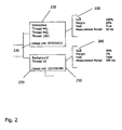
- Fig. 2 illustrates embodiments of groups of tasks. These groups may be based on the cgroup paradigm discussed above. Generally, data defining the groups of tasks may be stored in a policy such as policy 125 of Fig. 1 or separately therefrom and may be accessible by frequency governor 115.
- tasks are exemplarily grouped in two groups, interactive group 210 and background group 250.
- Group 210 is an exemplary grouping of three interactive tasks, represented by threads 441, 442 and 1001. These interactive tasks may require a relatively high core performance from a processor core because different or varying user interactions over time, for example with a graphical user interface, may suddenly require computationally intensive tasks to be swiftly completed (i.e. requiring a high frequency of operation).
- group 250 is a grouping comprising a background task, represented by thread 10. This background task may be adequately performed with a relatively low core performance from a processor core because the speed with which the task is to be executed is of relatively little importance and the tasks may be executed according to a relatively constant core performance.
- each group may be associated with group settings which specify parameters associated with executing tasks in the group as illustrated in Fig. 2 .
- Group settings may be stored together with the respective groups in a policy such as policy 125 of Fig. 1 .
- group settings of a group comprise a ceil parameter and a margin parameter for that group.
- the ceil parameter may be considered to be a target maximum usage of a core when the core is executing tasks in the group.
- the ceil parameter may define a maximum usage of a core which may be required for appropriately executing tasks in the group.
- the margin parameter may be considered to be a target margin maintained at an actual usage of the processor core and a frequency of operation of the processor core when the processor core is executing tasks in the group.
- the margin parameter may be thought of as defining a core performance tolerance for executing tasks in the associated group.
- Group settings further include other parameters such as a fast flag and a measurement period.
- the fast flag indicates a desire to step up to the maximum core performance under certain conditions
- the measurement period indicates a time interval at which it is desired for the frequency governor 115 to measure the usage of core(s) by tasks in the group and/or select/reselect a frequency of operation for the core(s) executing tasks in the group.
- the measurement period may be a normalized and/or common time interval across all the groups and so may be inherent to the groups and thus unnecessary to explicitly specify on a per group basis. Alternatively, the measurement period may be explicitly defined for each individual group as illustrated in Fig. 2 , and frequency governor 115 may perform measurements and frequency selection based upon one or more specified measurement periods.
- group 210 is associated with group settings 220 and group 250 is associated with group settings 260.
- Group settings 220 and 260 include a ceil parameter, a margin parameter, a fast flag and a measurement period.
- the tasks in group 210 require high core performance, while the task in group 250 is a background task requiring a relatively low core performance to be adequately performed.
- the different requirements of groups 210 and 250 are reflected in the different group settings associated with the two different groups.
- Group settings 220 reflect the need for a relatively high core performance: the ceil parameter is specified as 100% of core performance, the margin parameter is specified as a relatively high 20% and the fast flag is set to true.
- Group settings 260 reflect that the background task represented by thread 10 requires a relatively low core performance to be adequately performed: the ceil parameter is specified as 30% of core performance, the margin parameter is specified as a quite low 3% and the fast flag is set to false, indicating a stepwise increase in frequency is sufficient.
- the embodiments described herein leverage groups of tasks as defined above to dynamically vary the frequency of operation of a processor core to both optimize performance and conserve power consumption for the tasks executing on the processor core.
- the frequency governor may monitor the usage of one or more processor cores on a task level and select the frequency of operation of the processor core(s) based upon the monitored usage of the processor core(s) by the tasks in the groups.
- the frequency of operation and the corresponding voltage are set by the frequency governor at a processor core level based upon the combined usages of a processor core across the groups with tasks executing on the processor core, thus providing an optimized core performance at the processor core for executing tasks, while simultaneously minimizing power consumption of the processor core.
- the monitored usage of one or more processor cores may be combined across the groups on a per core basis through aggregation to determine an optimal frequency of operation of a processor core, which may then be used to select one of the available frequencies of operation of the processor core for the processor core to operate at.
- the usage of a processor core by the currently executing tasks is aggregated subject to or with one or more group settings to select one of the available frequencies of operation of the processor core for the core to run at.
- groups are used as a mechanism for monitoring and/or recording the usage of processor cores on a per group or per task level. More particularly, each group can be associated with one or more usage counters.
- the usage of any task in the group of the processor core may be monitored by the frequency governor (or any other component coupled to the frequency governor, such as a scheduler) and recorded in the counter. This may be done by the frequency governor for all tasks in the group, thus compiling a usage of the corresponding processor core by the tasks in the group.
- a group may then have at least one counter corresponding to each processor core.
- a counter can exist per task and per core and the usage of each task per core recorded for the groups. Then the logged usage across counters can be aggregated to determine the per core usage for the tasks in a group.
- the counter values or the monitored usage may be stored as parts of the group parameters in memory 120.
- the usage per core may be monitored per group or per executing task. The usages of processor cores across groups by executing tasks may provide an indication of the required future usage of cores.
- each group 210, 250 is associated with a single usage counter that logs the combined usage of a corresponding core by executing tasks in the respective group.
- Group 210 is associated with usage counter 230 and group 250 is associated with usage counter 270.
- the usage counter associated with the respective group is incremented based upon the core usage of the currently executing tasks in the group to monitor a usage of the corresponding core over a time period by any of the tasks in the group.
- the usage counters may be incremented based on the consumption of core cycles normalized with the core frequency by any of the tasks in the corresponding group.
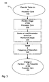
- Fig. 3 provides flow diagram 300 illustrating aspects of a method embodiment of the technique presented herein.
- multiple tasks are executed on a processor core such as core 110 of processor device 100a of Fig. 1.
- Figs. 1 and 2 will be used hereinafter as examples for discussing the steps of flow diagram 300.
- policy 125 comprises data structures defining groups 210 and 250 as well as corresponding group settings 220 and 260, corresponding to groups 210 and 250, respectively. Policy 125 further comprises usage counters 230 and 270, also corresponding to groups 210 and 250, respectively.
- step 310 multiple tasks are executing on a processor core such as core 110 of processor device 100a of Fig. 1 .
- the usage of the processor core is monitored.
- frequency governor 115 can access and use usage counters 230 and 270 to log the usage of processor core 110 by the executing tasks in respective groups 210 and 250, and then, at steps 330 and 340, aggregate the logged usage of processor core 110 by tasks of groups 210 and 250 subject to the group settings to derive an optimized frequency of operation for processor core 110, and based upon the derived optimized frequency, select a frequency of operation from among the discrete available frequency of operations supported by processor device 100a for processor core 110 to operate at.
- the technique disclosed herein can be extended to any number of processor cores and groups: two groups are merely used here for simplicity of example.
- each group 210, 250 in policy 125 is associated with group settings 220, 260 that contain a measurement period.
- This specified measurement period indicates a period for measuring the usage of processor core 110 for the groups and for selecting a frequency of operation.
- group 210 is a grouping of interactive tasks that may vary more strongly in core performance requirements, the measurement period is a relatively short 50 milliseconds (ms) which thus specifies that the measuring of usage and selecting a frequency is to occur periodically every 50 ms.
- group 250 because group 250 contains a background task which typically has a fairly constant core performance requirement, the measurement period is a relatively long 500 ms.
- the period for performing the usage measurements may be taken as the shortest measurement period across the groups (i.e., 50 ms in the above example).
- the frequency governor can choose its own measurement period or may use a combination of the measurement periods of the groups, or select any of the measurement periods of the groups depending on various constraints, such as, for example, usage of the core and importance of the tasks executing.
- measuring the usage of the groups and selecting the frequency of operation may or may not occur periodically, or any of the combination of the above may be used.
- usage counters 230 and 270 may be set to zero.
- a monotonically increasing counter may be used also. In such a case the difference in counts between two successive measurement periods would be calculated.
- the usage of processor core 110 by threads 441, 442 and 1001 is logged in counter 230 by frequency governor 115 by incrementing counter 230 by each core usage cycle of threads 441, 442 and 1001, thus compiling the usage of processor core 110 by the tasks in group 210.
- the usage of processor core 110 by thread 10 is logged in counter 270 by frequency governor 115 by incrementing counter 270 by each core usage cycle of thread 10, thus compiling the usage of core 110 by the tasks in group 250.
- step 330 usage may be aggregated across groups 210 and 250 subject to the respective group settings (e.g., ceil and margin parameters) to arrive at a load parameter indicative of the combined usage by the tasks in groups 210 and 250 on processor core 110.
- this load parameter may be used to determine an optimal frequency of operation which can be used to select a frequency of operation of core 110 if necessary. For example, if the load parameter indicates that the current frequency of operation of core 110 is too low, the frequency of operation can be raised to an appropriate frequency of operation. Conversely, if the load parameter indicates that the current frequency of operation of core 110 is too high, the frequency of operation can be lowered to an appropriate frequency of operation.
- the frequency governor can control the clock source and the power source to operate at the selected frequency of operation and corresponding voltage, respectively.
- a frequency of operation at step 340 with respect to Fig. 1 . If the optimum frequency of operation is above the current frequency of operation of core 110, then if the fast flag is set to no, the frequency of operation of the core is increased in a stepwise manner to the next available discrete frequency of operation. If, however, the fast flag is set to yes, thus indicating that at least one of the relevant groups contains one or more tasks that may require a maximum core performance to be made available, then the frequency of operation of core 110 is increased to the maximum available discrete frequency of operation and the core shall run at the corresponding maximum voltage.
- optimum frequency of operation is below the current frequency of operation of core 110, then more core performance than is sufficient to execute all the tasks in the groups is being provided. That is, relating the above to the usage of core 110, core 110 is maintaining a larger margin of unused core performance than is necessary. If a lower discrete frequency of operation is available that is equal to or greater than the optimum frequency of operation, then the lowest available discrete frequency of operation that is equal to or greater than the optimum frequency of operation is selected as the new frequency of operation of core 110.
- steps 310 to 350 may be carried out at periodic or varying intervals of time to dynamically change the frequency of operation of core 110. Because the frequency of operation is dynamically varied at the level of core 110, a frequency of operation of core 110 is continually selected that provides sufficient core performance to execute the tasks while simultaneously conserving power by using less power per cycle by, for example, operating at a lower frequency and a lower voltage.
- steps 310-350 when applied across a multi-core processor, steps 310-350 will be performed for each of the processor cores and a frequency of operation selected across the processor device and/or per processor core of the processor device.
- this parameter can be used for purposes of the above technique to define a "ceiling" limiting (or clipping) the usage aggregated for a group to an appropriate usage for the group when determining the load parameter at step 330. For example, take the instance where none of threads 441, 442 or 1001 are (currently) executing on core 110.
- the ceil parameter provides a ceil specifying the maximum appropriate usage that is to be used for purposes of aggregation for a group. (Needless to say, a group may or may not have a ceil parameter. When a group has group settings specifying a ceil parameter, the usage across the groups is aggregated with the aggregated usage of the group subject to, for example, limited to, the respective ceil parameter for that group.)
- the maximum usage that can be aggregated for group 250 is limited by the ceil parameter of 30%.
- the maximum usage that can be aggregated for processor core 110 is 100%.
- the different ceil parameters for groups 210 and 250 reflect the different types of tasks contained in the groups.
- Group 210 is a grouping of interactive tasks and when the user is interacting with a GUI or other interface, the required core performance will be high and core resources should be allocated to the tasks: accordingly the ceil parameter for group 210 is set to 100%.
- group 250 contains background tasks and so a limited ceil parameter of 30% appropriately limits the usage that can be aggregated for this group for purposes of setting the frequency of operation of processor core 110.
- frequency governor 115 may select and/or compute a desired margin parameter, referred to hereinafter as maximized margin parameter, across the groups based on the margin parameters as specified for the groups in the group settings. Referring to flow diagram 300 of Fig. 3 , this may be one aspect of steps 330 and 340.
- the maximized margin parameter may be added to the load parameter to provide and/or incorporate a tolerance which allows for selecting a frequency of operation with the appropriate tolerance for potential changes in usage by groups over time.
- the margin parameter may generally specify an appropriate tolerance for its respective group. More particularly, the margin parameter may function as a target margin between an actual usage of the processor core and a target frequency of operation of the processor core.
- a margin parameter may be set on a per group basis based on the likely necessary variation in usage due to executing the tasks in the group over time. For example, because group 210 contains interactive tasks, which may vary relatively significantly in required usage over time, a relatively large tolerance may be required; this is reflected in the relatively high margin parameter of 20% specified in group settings 220. With regard to group 250, because group 250 contains background tasks, which may have relatively constant required usage over time, a relatively small tolerance may be all that is required; this is reflected in the quite low margin parameter of 3% specified in example group settings 260.
- Frequency governor 115 may determine and/or calculate the maximized margin parameter across the groups by, in one aspect, selecting the largest margin parameter from among the margin parameters of the groups with tasks executing on processor core 110. In other aspects, the frequency governor may take an average of the margin parameters across the groups, determine a maximized margin parameter based on historical usage of the processor core(s) by tasks in the groups or use any number of other algorithms to determine the maximized margin parameter. With regard to Fig. 2 , assuming that one of the tasks of group 210 is executing on processor core 110, the largest margin parameter across groups 210, 250 is the 20% margin specified in group settings 220 of group 210. Accordingly, this 20% margin may be used as the maximized margin parameter by frequency governor 115.
- the ceil parameter may also be used to limit the margin parameters and/or the maximized margin parameter.
- the usage and the margin parameter for each group can be combined, and the margin parameter reduced by any amount the combined usage and margin parameter for that group is over the corresponding ceil parameter for that group.
- Frequency governor 115 may use both the load parameter L(m) determined according to the above equation (1) and the maximized margin parameter M(m) determined according to the above equation (2) to select a frequency of operation for processor core 110 to operate at. More particularly, in one aspect, the load parameter L(m) and the maximized margin parameter M(m) may be summed (see Figs. 4a-4e ) and a frequency value may be derived from the resulting sum, by, for example, multiplying the sum by a frequency factor to arrive at a derived optimal frequency for processor core 110. Frequency governor 115 may then use the derived optimal frequency to select, in step 340 of Fig. 3 , the frequency of operation from one of the available discrete frequencies of operation supported by processor device 100. Of course, in many instances, the selected frequency of operation will be the same as the current frequency of operation of the processor core and the governor will not change the frequency of operation of processor core 110.
- Figs. 4a-4e are graphical representations of aggregating usage across groups utilizing the technique and aspects thereof described above, and in particular, equations (1) and (2). More particularly, Figs. 4a-4e can be used to illustrated further aspects of the technique described above with regard to Figs. 1-3 .
- Fig. 4a is a diagrammatic representation of usage over time and monitoring the same for a single core and a single group, group G1.
- a ceil parameter for group G1 specifies a limiting ceil, ceil1, for group G1.
- the usage is monitored by a frequency governor, for example frequency governor 115 of processor device 100a of Fig. 1 , for group G1 at times T1, T2, T3 and T4 based on the corresponding group settings.
- the monitored usage and the margin parameter are below ceil1 and are taken as the combined load parameter and maximized margin parameter which are used by a frequency governor to select a frequency of operation.
- the combined load parameter and maximized margin parameter are above ceil1 by a portion of the margin parameter: the margin parameter is reduced by the amount above ceil1 to provide a maximized margin parameter which is combined with the load parameter, here usage U1, to derive the optimal frequency used by a frequency governor to select a frequency of operation.
- the usage for the single group is above ceil1, and thus the load parameter in this example is taken as the usage limited by ceil1.
- the margin parameter is not added to the load parameter because the usage already exceeds the ceil.
- Fig. 4b is a diagrammatic representation illustrating selecting a maximized margin parameter in the case of two groups and one core.
- group G2 has no tasks which are executing on the associated core, while G1 has tasks which are executing on the associated core with a usage U1.
- the margin parameter of group G2 is not selected as the maximized margin parameter and consequently not summed with usage U1, but is instead ignored and a frequency of operation selected from the summation of the load parameter (in this case usage U1, because group G2 has no usage) and margin parameter M1 of group 1.
- Fig. 4c is a diagrammatic representation illustrating aspects of the above techniques over time T1, T2, T3 and T4 with regard to one core and two groups G1 and G2.
- usage U1 corresponding to the tasks in group G1 is aggregated with usage U2 corresponding to the tasks in group G2 to derive a load parameter.
- margin parameter M2 of group G2 is the largest margin parameter across groups G1 and G2, it is selected as the maximized margin parameter added to the load parameter to provide a tolerance margin (for the frequency of operation selected by the governor) as shown in the combination at T1.
- the usage U1 measured for group G1 exceeds ceil1 for group G1 and so is limited to ceil1 when aggregating usage U1 with usage U2 to determine the load parameter as shown in the combination at time T4 on the right.
- Fig. 4d at times T1 and T2, the usages U1 and U2 are aggregated across groups as described above to arrive at a load parameter, as seen in the corresponding combinations on the right. Similarly, the maximized margin parameter is selected across groups G1, G2 as described above. At time T3, the combined usage U1 and margin parameter M1 for group G1 are above corresponding ceil1. Accordingly, M1 is reduced by the portion of M1 above ceil1 because M1 and ceil1 correspond to the same group G1. The reduced M1 is used when selecting the maximized margin parameter across groups G1, G2, but because the reduced M1 is still greater than margin parameter M2 of group G2, it is selected as the maximized margin parameter to sum with the load parameter as shown in the combination at the right at time T3.
- the usage U1 of group G1 exceeds ceil1 specified for group G1 and so both the usage U1 is limited by ceil1 for purposes of aggregating usages U1 and U2 to arrive at a load parameter as previously discussed, and furthermore, margin M1 of group G1 is ignored for purposes of selecting the maximized margin parameter across groups G1, G2 and margin parameter M2 is selected as the maximized margin parameter. This is illustrated in the combination at time T4 on the right.
- frequency governor 115 is operable to access policy 125 stored in memory 120.
- Policy 125 comprises definition of groups of tasks and corresponding group settings.
- Frequency governor 115 is further operable to control power and frequency controller module 130 which in turn is operable to control the clock source and the power source to provide a number of discrete frequencies and corresponding voltages to processor cores 1 to 4.
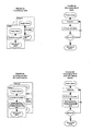
- Figs. 5a to 5d are flow diagrams illustrating aspects for extending the technique described in relation to a processor device with a single processor core to a multi-core processor device.
- Fig. 5a illustrates that the frequency governor 115 may run as a background task which periodically awakens with regard to each processor core of a multi-core processor and performs a core analysis similar to the analysis described with relation to Fig. 3 for the respective processor core.
- Fig. 5b illustrates a technique whereby the frequency governor 115 may sequentially perform a core analysis for each processor core of a multi-core processor at each wakening.
- Figs. 5c and 5d are flow diagrams illustrating similar techniques with regard to extending the technique of Fig. 3 across multiple processor cores, but with regard to groups or cores associated with different latency periods for performing the core analysis.
- the periodic wake-up and/or latency period of Figs. 5a-5d correspond to one or more measurement periods of the groups.
- the minimum latency period across the groups is selected as the time period for implementing the above technique across the cores and/or groups.
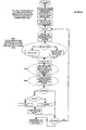
- Figs. 6a-6e are detailed flow diagrams of pseudo-code steps used to implement aspects of the above described technique and provide very specific implementation examples.
- subroutines 610a of Fig. 6a , 610c of Fig. 6c and 610d of Fig. 6d effect equation (1).
- subroutines 620a of Fig. 6a , 620c of Fig. 6c and 620d of Fig. 6d effect equation (2).
- Subroutine 630a of Fig. 6a further shows a very detailed process for normalizing a group ceil parameter encompassing multiple processor cores relative to a single processor core ceil parameter to arrive at a normalized single processor core ceil parameter with a maximum value of 100% in a multi-core processor device.
- Subroutines 630c and 630d of Figs. 6c and 6d show a very detailed subroutine for normalizing a usage of a multi-core processor device (which may exceed 100%) to a normalized maximum of 100% for each processor core.
- Subroutine 630e of Fig. 6e illustrates a detailed subroutine for determining if a fast flag associated with a multi-core processor device is to be disregarded for purposes of raising the frequency of operation to the maximum frequency of operation for the multi-core processor device.
- the pseudo-code representations of Figs. 6a-6e are believed to be self-explanatory in the light of the above description, a more detailed discussion thereof is omitted herein.
- steps 310 to 350 of Fig. 3 may generally be carried out at periodic or varying intervals of time to dynamically change the frequency of operation of processor cores 1-4 of Fig. 1 for example in accordance with Figs. 5a-5c and Figs. 6a-6e . Because the frequency of operation is dynamically varied at the level of the processor cores, a frequency of operation for the cores is continually selected that provides sufficient core performance to execute the tasks while simultaneously conserving power by minimizing the power expended per frequency cycle.
- the highest frequency of operation selected for a processor core of the multiple processor cores may in turn be selected as the optimal frequency of operation for the processor cores of the processor device.
- the optimal frequency of operation of the processor cores may be compared with the actual frequency of operation of the cores. If the optimum frequency of operation is above the current frequency of operation of the processor cores of the processor device, then if all fast flags are set to no, the frequency of operation of the processor cores may be increased in a stepwise manner to the next available discrete frequency of operation for the processor device.
- a fast flag is set to yes, thus indicating that at least one of the relevant groups contains one or more tasks requiring a maximum core performance to be available, then the frequency of operation of the processor cores is increased to the maximum available discrete frequency of operation and the selected core shall run at the corresponding maximum voltage.
- individual fast flags are examined per processor core: if it is determined that the processor cores corresponding to the set fast flags do not require additional core performance, said fast flags are disregarded for setting a maximum frequency of operation.
- the optimum frequency of operation is below the current frequency of operation of the selected core, then more core performance than is sufficient to execute all the tasks in the groups is being provided. That is, relating the above to the physical usage of the selected core, the selected core is maintaining a larger margin of core performance than is necessary. If a lower discrete frequency of operation is available that is equal to or greater than the optimum frequency of operation, then the lowest available discrete frequency of operation that is equal to or greater than the optimum frequency of operation is selected as the new frequency of operation of the selected core.
- the frequency of operation of individual processor cores may be selected individually according to the above-described technique.
- the processor cores may operate at different frequencies relative to each other.
- the usage can be expressed relative to an absolute maximum or minimum frequency of operation of the core.
- the advantage of expressing usage relative to these absolute values is that in implementation, when the above discussed equations are executed using these absolute values, a possible division by the frequency governor executing on the core(s) is avoided. As would be understood by one of skill in the art, executing division operations may be computationally expensive, and thus avoiding the same reduces the computation resources required to implement the above techniques on the core(s).
- the above-disclosed embodiments define a technique for operating or using a processor device which minimizes power consumption while still maintaining the necessary frequency of operation for sufficient processing performance of software threads/tasks.
- the technique disclosed herein may thus provide for dynamically varying the frequency of operation of the processor core(s) of a processor device to select a lowest frequency of operation of the core which maintains the appropriate core performance for the tasks to be executed on the core(s). More particularly, the technique disclosed herein may be implemented to minimize wasted core performance, while preserving an appropriate level of core performance to execute tasks. Thus, power is conserved while simultaneously a level of core performance appropriate to the tasks to be executed can be maintained.
- the frequency of operation of the core(s) may thus be varied over time to minimize frequency and the voltage of operation, thus conserving power, while simultaneously running at a frequency of operation which maintains a level of core performance appropriate to the tasks to be executed.
- the technique disclosed herein may be even more effective, because the frequency of operation may be set individually for each core, allowing for minimizing frequency for each individual core, while still providing an optimal level of performance for the tasks scheduled to be executed on the individual cores. Because in this example, different cores may run at different frequencies, using the technique herein, wasted core performance is further reduced, thus conserving yet a further margin of power.
- one of the cores may generally execute graphics-intensive tasks, while the other core may generally execute background tasks.
- the graphics-intensive tasks may require high core performance to allow for executing computationally intensive tasks, thus requiring the core to operate at a high frequency of operation and maintain a relatively high core performance, while the other core which executes primarily background tasks may operate at a relatively lower frequency of operation and require only a relatively low core performance because the background tasks may have a relatively constant core performance requirement.
Landscapes
- Engineering & Computer Science (AREA)
- Theoretical Computer Science (AREA)
- Physics & Mathematics (AREA)
- General Engineering & Computer Science (AREA)
- General Physics & Mathematics (AREA)
- Power Sources (AREA)
Claims (26)
- Verfahren zum Betreiben einer Prozessorvorrichtung (100a-100c), welche mindestens einen Prozessorkern (1-4, 110) aufweist, wobei das Verfahren umfasst:Ausführen mehrerer Aufgaben (441, 442, 1001, 10) auf dem mindestens einen Prozessorkern, wobei die mehreren Aufgaben in mindestens zwei Gruppen derart gruppiert sind, dass Aufgaben von mindestens zwei (210-250) verschiedenen Gruppen auf dem mindestens einen Prozessorkern ablaufen, wobei Aufgaben von den mindestens zwei Gruppen, welche auf dem mindestens einen Prozessorkern ablaufen, relativ zueinander abweichende Anforderungen an die Kernleistung aufweisen und jeder der mindestens zwei Gruppen eine oder mehrere Gruppeneinstellungen (220-260) zugeordnet sind, welche die abweichenden Anforderungen an die Kernleistung widerspiegeln;Überwachen der Nutzung (320) des mindestens einen Prozessorkerns durch Aufgaben in den mindestens zwei verschiedenen Gruppen und Kompilieren der überwachten Nutzungen auf einer Gruppenbasis;Aggregieren (330) der kompilierten Nutzungen des mindestens einen Prozessorkerns über die mindestens zwei verschiedenen Gruppen gemäß der einen oder den mehreren Gruppeneinstellungen, um eine Nutzung des mindestens einen Prozessorkerns durch die mindestens zwei verschiedenen Gruppen zu bestimmen, wobei die eine oder die mehreren Gruppeneinstellungen den jeweiligen Beitrag von jeder der einzelnen Gruppen zur Aggregation steuern;Ableiten eines Lastparameters (330) für den mindestens einen Prozessorkern basierend auf der bestimmten Nutzung des Prozessorkerns durch die mindestens zwei verschiedenen Gruppen, wobei der Lastparameter auf die aggregierte Nutzung des mindestens einen Prozessorkerns durch die Aufgaben in den Gruppen, wie durch die eine oder die mehreren Gruppeneinstellungen gesteuert, über die mindestens zwei verschiedenen Gruppen schließen lässt;Auswählen einer Betriebsfrequenz (340) für den mindestens einen Prozessorkern basierend auf dem Lastparameter;Ändern der Betriebsfrequenz (350) des mindestens einen Prozessorkerns auf die ausgewählte Betriebsfrequenz.
- Verfahren nach Anspruch 1, wobei Überwachen der Nutzung des mindestens einen Prozessorkerns wiederholtes Messen der Nutzung des mindestens einen Prozessorkerns durch einzelne Aufgaben in den mindestens zwei verschiedenen Gruppen auf einer Gruppenbasis im Zeitverlauf umfasst.
- Verfahren nach einem der vorangehenden Ansprüche, wobei die eine oder die mehreren Gruppeneinstellungen für eine oder mehrere der Gruppen eine Messperiode für die jeweilige der einen oder mehreren der Gruppen umfasst und wobei das Ableiten des Lastparameters periodisch basierend auf der mindestens einen Messperiode durchgeführt wird.
- Verfahren nach einem der vorangehenden Ansprüche, wobei die Gruppeneinstellungen mindestens einen von einem ceil-Parameter und einem margin-Parameter umfassen, wobei es sich beim ceil-Parameter um eine angestrebte Maximalnutzung des mindestens einen Prozessorkerns durch die Aufgaben in der zugeordneten Gruppe und beim margin-Parameter um eine angestrebte Spanne zwischen einer Nutzung des Prozessorkerns und einer angestrebten Betriebsfrequenz des Prozessorkerns handelt.
- Verfahren nach Anspruch 4, wobei die Gruppeneinstellungen einer oder mehrerer Gruppen kombiniert werden, um einen maximierten margin-Parameter für den mindestens einen Kern abzuleiten.
- Verfahren nach Anspruch 5, wobei das Ableiten des maximierten margin-Parameters Auswählen eines größten margin-Parameters gemäß den Gruppeneinstellungen der einzelnen Gruppen und/oder der Nutzung des mindestens einen Kerns durch eine oder mehrere Gruppen umfasst.
- Verfahren nach Anspruch 6, wobei der ausgewählte größte margin-Parameter basierend auf einem Zusammenhang zwischen der gemessenen Nutzung und den Gruppeneinstellungen einer oder mehrerer Gruppen oder basierend auf der Nutzung des mindestens einen Kerns durch die Gruppe, welche dem ausgewählten größten margin-Parameter entspricht, unterhalb eines minimalen Nutzungsgrenzwerts reduziert wird.
- Verfahren nach einem der vorangehenden Ansprüche, wobei jede Gruppe mindestens einem Nutzungsprotokoll zugeordnet ist, wobei jedes Nutzungsprotokoll einem Prozessorkern entspricht und wobei das Verfahren weiter umfasst:Protokollieren, für jede Gruppe, der Nutzung des mindestens einen Kerns durch die Aufgaben in der Gruppe in dem Nutzungsprotokoll, welches der Gruppe zugeordnet ist und dem mindestens einen Kern entspricht.
- Verfahren nach einem der Ansprüche 5 bis 7, wobei das Auswählen einer Betriebsfrequenz basierend auf dem Lastparameter umfasst:Summieren des Lastparameters und des maximierten margin-Parameters;Ableiten eines Frequenzwerts von der Summierung des Lastparameters und des maximierten margin-Parameters; undAuswählen der Betriebsfrequenz und, optional, einer entsprechenden Spannung für den mindestens einen Prozessorkern basierend auf dem abgeleiteten Frequenzwert.
- Verfahren nach einem der Ansprüche 5 bis 7 oder 9, wobei der Lastparameter auf dem mindestens einen Prozessorkern ist:

wobei L(m) der Lastparameter bezüglich des mindestens einen Prozessorkerns, m die laufende Messperiode, i die Gruppe ist, die ceil(i) und margin(i) Gruppeneinstellungen der Gruppe i sind, und usage(i) die gemessene Nutzung des mindestens einen Kerns durch Gruppe i ist und der laufenden Messperiode m entspricht; und
wobei der maximierte margin-Parameter auf dem mindestens ein Prozessorkern ist:
- Verfahren nach einem der vorangehenden Ansprüche, wobei der mindestens eine Prozessorkern bei diskreten Frequenzen betrieben wird, wobei die Betriebsfrequenz des mindestens einen Prozessorkerns als eine der verfügbaren diskreten Frequenzen ausgewählt wird, um eine Toleranzspanne für den Prozessorkern zu erhalten.
- Verfahren nach einem der vorangehenden Ansprüche, wobei eine höchste Betriebsfrequenz, welche durch den mindestens einen Prozessorkern unterstützt wird, basierend auf den Gruppeneinstellungen ausgewählt wird.
- Verfahren nach einem der vorangehenden Ansprüche, wobei sich die Betriebsfrequenz des mindestens einen Prozessorkerns von der Betriebsfrequenz von einem oder mehreren anderen Prozessorkernen der Prozessorvorrichtung unterscheidet.
- Prozessorsystem, umfassend:eine Prozessorvorrichtung (100a-100c) mit mindestens einem Prozessorkern (1-4, 110), wobei der mindestens eine Prozessorkern betreibbar ist, mehrere Aufgaben (441, 442, 1001, 10) auszuführen, welche in Gruppen (210, 250) gruppiert sind, wobei die mehreren Aufgaben von mindestens zwei verschiedenen Gruppen derart sind, dass der mindestens eine Prozessorkern Aufgaben von mindestens zwei verschiedenen Gruppen ausführt, wobei Aufgaben von den mindestens zwei verschiedenen Gruppen relativ zueinander abweichende Anforderungen an die Kernleistung aufweisen und jede der mindestens zwei verschiedenen Gruppen einer oder mehreren Gruppeneinstellungen (220-260) zugeordnet ist, welche die abweichenden Anforderungen an die Kernleistung widerspiegeln; undeinen Frequenzregler (115), der betreibbar ist:die Nutzung des mindestens einen Prozessorkerns durch Aufgaben in den mindestens zwei verschiedenen Gruppen zu überwachen (320) und die überwachte Nutzung auf einer Gruppenbasis zu kompilieren;die kompilierten Nutzungen des mindestens einen Prozessorkerns über die mindestens zwei verschiedenen Gruppen gemäß der einen oder den mehreren Gruppeneinstellungen zu aggregieren (330), um eine Nutzung des mindestens einen Prozessorkerns durch die mindestens zwei verschiedenen Gruppen zu bestimmen, wobei die eine oder die mehreren Gruppeneinstellungen den jeweiligen Beitrag von jeder der einzelnen Gruppen zur Aggregation steuern;einen Lastparameters (330) für den mindestens einen Prozessorkern basierend auf der bestimmten Nutzung des Prozessorkerns durch die mindestens zwei verschiedenen Gruppe abzuleiten, wobei der Lastparameter auf die aggregierte Nutzung des mindestens einen Prozessorkerns durch die Aufgaben in den Gruppen, wie durch die eine oder die mehreren Gruppeneinstellungen gesteuert, über die mindestens zwei verschiedenen Gruppen schließen lässt;eine Betriebsfrequenz für den mindestens einen Prozessorkern basierend auf dem Lastparameter auszuwählen (340);die Betriebsfrequenz des mindestens einen Prozessorkerns auf die ausgewählte Betriebsfrequenz zu ändern (350).
- Prozessorsystem nach Anspruch 14, wobei der Frequenzregler betreibbar ist, die Nutzung des mindestens einen Prozessorkerns durch wiederholtes Messen der Nutzung des mindestens einen Prozessorkern durch einzelne Aufgaben in den mindestens zwei verschiedenen Gruppen auf einer Gruppenbasis im Zeitverlauf zu überwachen.
- Prozessorsystem nach Anspruch 14 oder 15, wobei die eine oder die mehreren Gruppeneinstellungen für eine oder mehrere der Gruppen einen Messperiode für die jeweilige der einen oder mehreren der Gruppen umfasst und wobei der Frequenzregler betreibbar ist, das Ableiten des Lastparameters basierend auf der mindestens einen Messperiode periodisch durchzuführen.
- Prozessorsystem nach einem der Ansprüche 14 bis 16, wobei die Gruppeneinstellungen mindestens einen von einem ceil-Parameter und einem margin-Parameter umfassen, wobei es sich beim ceil-Parameter um eine angestrebte Maximalnutzung des mindestens einen Prozessorkerns durch die Aufgaben in der zugeordneten Gruppe und beim margin-Parameter um eine angestrebte Spanne zwischen einer Nutzung des Prozessorkerns und einer angestrebten Betriebsfrequenz des Prozessorkerns handelt.
- Prozessorsystem nach Anspruch 17, wobei das System betreibbar ist, die Gruppeneinstellungen einer oder mehrerer Gruppen zu kombinieren, um einen maximierten margin-Parameter für den mindestens einen Kern abzuleiten.
- Prozessorsystem nach Anspruch 18, wobei das System betreibbar ist, den maximierten margin-Parameter durch Auswählen eines größten margin-Parameters gemäß den Gruppeneinstellungen der einzelnen Gruppen und/oder der Nutzung des mindestens einen Kerns durch eine oder mehrere Gruppen abzuleiten.
- Prozessorsystem nach Anspruch 19, wobei das System betreibbar ist, den ausgewählten größten margin-Parameter basierend auf einem Zusammenhang zwischen der gemessenen Nutzung und den Gruppeneinstellungen einer oder mehrerer Gruppen oder basierend auf der Nutzung des mindestens einen Kerns durch die Gruppe, welche dem ausgewählten größten margin-Parameter entspricht, unterhalb eines minimalen Nutzungsgrenzwerts zu reduzieren.
- Prozessorsystem nach einem der Ansprüche 14 bis 20, wobei jede Gruppe mindestens einem Nutzungsprotokoll zugeordnet ist, wobei jedes Nutzungsprotokoll einem Prozessorkern entspricht und wobei der Frequenzregler weiter betreibbar ist:für jede Gruppe die Nutzung des mindestens einen Kerns durch die Aufgaben in der Gruppe in dem Nutzungsprotokoll zu protokollieren, welches der Gruppe zugeordnet ist und dem mindestens einen Kern entspricht.
- Prozessorsystem nach einem der Ansprüche 18 bis 20, wobei der Frequenzregler betreibbar ist, eine Betriebsfrequenz basierend auf dem Lastparameter auszuwählen durch:Summieren des Lastparameters und des maximierten margin-Parameters;Ableiten eines Frequenzwerts von der Summierung des Lastparameters und des maximierten margin-Parameters; undAuswählen der Betriebsfrequenz und, optional, einer entsprechenden Spannung für den mindestens einen Prozessorkern basierend auf dem abgeleiteten Frequenzwert.
- Prozessorsystem nach einem der Ansprüche 18 bis 20 oder 22, wobei der Lastparameter auf dem mindestens einen Prozessorkern ist:

wobei L(m) der Lastparameter bezüglich des mindestens einen Prozessorkerns ist, m die laufende Messperiode, i die Gruppe ist, die ceil(i) und die margin(i) Gruppeneinstellungen der Gruppe i sind, und usage(i) die gemessene Nutzung des mindestens einen Kerns durch Gruppe i ist und der laufenden Messperiode m entspricht; und
wobei der maximierte margin-Parameter auf dem mindestens ein Prozessorkern ist:
- Prozessorsystem nach einem der Ansprüche 14 bis 23, wobei der mindestens eine Prozessorkern bei diskreten Frequenzen betrieben wird und wobei der Frequenzregler betreibbar ist, die Betriebsfrequenz des mindestens einen Prozessorkerns als eine der verfügbaren diskreten Frequenzen zu setzen, um eine Toleranzspanne für den Prozessorkern zu erhalten.
- Prozessorsystem nach einem der Ansprüche 14 bis 24, wobei der Frequenzregler betreibbar ist, eine höchste Betriebsfrequenz, welche durch den mindestens einen Prozessorkern unterstützt ist, basierend auf den Gruppeneinstellungen zu setzen.
- Prozessorsystem nach einem der Ansprüche 14 bis 25, wobei sich die Betriebsfrequenz des mindestens einen Prozessorkerns von der Betriebsfrequenz von einem oder mehreren anderen Prozessorkernen der Prozessorvorrichtung unterscheidet.
Priority Applications (4)
| Application Number | Priority Date | Filing Date | Title |
|---|---|---|---|
| EP10001951.2A EP2362297B1 (de) | 2010-02-25 | 2010-02-25 | Technik zur Auswahl einer Betriebsfrequenz in einem Prozessorsystem |
| PCT/EP2011/052626 WO2011104245A1 (en) | 2010-02-25 | 2011-02-22 | Technique for selecting a frequency of operation in a processor system |
| US13/579,923 US9086876B2 (en) | 2010-02-25 | 2011-02-22 | Technique for selecting a frequency of operation in a processor system |
| IN6621DEN2012 IN2012DN06621A (de) | 2010-02-25 | 2012-07-26 |
Applications Claiming Priority (1)
| Application Number | Priority Date | Filing Date | Title |
|---|---|---|---|
| EP10001951.2A EP2362297B1 (de) | 2010-02-25 | 2010-02-25 | Technik zur Auswahl einer Betriebsfrequenz in einem Prozessorsystem |
Publications (2)
| Publication Number | Publication Date |
|---|---|
| EP2362297A1 EP2362297A1 (de) | 2011-08-31 |
| EP2362297B1 true EP2362297B1 (de) | 2014-05-14 |
Family
ID=42321144
Family Applications (1)
| Application Number | Title | Priority Date | Filing Date |
|---|---|---|---|
| EP10001951.2A Active EP2362297B1 (de) | 2010-02-25 | 2010-02-25 | Technik zur Auswahl einer Betriebsfrequenz in einem Prozessorsystem |
Country Status (4)
| Country | Link |
|---|---|
| US (1) | US9086876B2 (de) |
| EP (1) | EP2362297B1 (de) |
| IN (1) | IN2012DN06621A (de) |
| WO (1) | WO2011104245A1 (de) |
Cited By (1)
| Publication number | Priority date | Publication date | Assignee | Title |
|---|---|---|---|---|
| US10521267B2 (en) | 2015-12-21 | 2019-12-31 | Telefonaktiebolaget Lm Ericsson (Publ) | Priority trainer for many core processing system |
Families Citing this family (31)
| Publication number | Priority date | Publication date | Assignee | Title |
|---|---|---|---|---|
| US9052901B2 (en) * | 2011-12-14 | 2015-06-09 | Intel Corporation | Method, apparatus, and system for energy efficiency and energy conservation including configurable maximum processor current |
| KR101899811B1 (ko) * | 2012-04-04 | 2018-09-20 | 엘지전자 주식회사 | 이동 단말기 및 그 제어 방법, 이를 위한 기록 매체 |
| KR101842200B1 (ko) * | 2012-01-31 | 2018-03-26 | 엘지전자 주식회사 | 이동 단말기 및 그 제어방법 |
| US9137848B2 (en) * | 2012-01-31 | 2015-09-15 | Lg Electronics Inc. | Mobile terminal, controlling method thereof and recording medium thereof |
| US8904204B2 (en) * | 2012-06-29 | 2014-12-02 | International Business Machines Corporation | Managing computing resources through aggregated core management |
| JP6060756B2 (ja) * | 2013-03-18 | 2017-01-18 | 富士通株式会社 | 周波数制御装置、周波数制御方法および周波数制御プログラム |
| US9400518B2 (en) * | 2013-06-05 | 2016-07-26 | Qualcomm Innovation Center, Inc. | Temporary frequency adjustment of mobile device processors based on task migration |
| CN105830046A (zh) * | 2013-08-15 | 2016-08-03 | 英派尔科技开发有限公司 | 具有基于石墨烯的晶体管的异构多核处理器 |
| US9625971B2 (en) | 2014-01-10 | 2017-04-18 | Taiwan Semiconductor Manufacturing Company, Ltd. | System and method of adaptive voltage frequency scaling |
| US20150309552A1 (en) * | 2014-04-25 | 2015-10-29 | Qualcomm Innovation Center, Inc. | Enhancement in linux ondemand governor for periodic loads |
| KR102169692B1 (ko) | 2014-07-08 | 2020-10-26 | 삼성전자주식회사 | 멀티-코어 프로세서를 포함하는 시스템 온 칩 및 그것의 동적 전력 관리 방법 |
| KR102270239B1 (ko) * | 2014-08-07 | 2021-06-28 | 삼성전자 주식회사 | 전자장치에서 소프트웨어를 실행하기 위한 방법 및 장치 |
| US9753836B2 (en) | 2014-09-12 | 2017-09-05 | Intel Corporation | Low power debug architecture for system-on-chips (SoCs) and systems |
| US20160055615A1 (en) * | 2014-11-11 | 2016-02-25 | Mediatek Inc. | Smart Frequency Boost For Graphics-Processing Hardware |
| US20160147545A1 (en) * | 2014-11-20 | 2016-05-26 | Stmicroelectronics International N.V. | Real-Time Optimization of Many-Core Systems |
| US20160292015A1 (en) * | 2015-04-03 | 2016-10-06 | Qualcomm Innovation Center, Inc. | Processor frequency scaling based upon load tracking of dependent tasks |
| US20160378471A1 (en) * | 2015-06-25 | 2016-12-29 | Intel IP Corporation | Instruction and logic for execution context groups for parallel processing |
| US10025641B2 (en) * | 2015-09-15 | 2018-07-17 | Qualcomm Incorporated | Workload differentiation for processor frequency scaling |
| KR102528692B1 (ko) * | 2016-01-04 | 2023-05-08 | 한국전자통신연구원 | 중앙처리장치의 동적 주파수 조절 장치 및 그 방법 |
| US10597767B2 (en) | 2016-02-22 | 2020-03-24 | Roswell Biotechnologies, Inc. | Nanoparticle fabrication |
| CN105955827B (zh) * | 2016-05-31 | 2017-11-24 | 广东欧珀移动通信有限公司 | 处理器计算资源的分配方法及装置 |
| US10503238B2 (en) | 2016-11-01 | 2019-12-10 | Microsoft Technology Licensing, Llc | Thread importance based processor core parking and frequency selection |
| US10372494B2 (en) | 2016-11-04 | 2019-08-06 | Microsoft Technology Licensing, Llc | Thread importance based processor core partitioning |
| KR20180107948A (ko) * | 2017-03-23 | 2018-10-04 | 한국전자통신연구원 | 이종 멀티코어 시스템 기반 거버너 제어 장치 및 방법 |
| CN110609777B (zh) * | 2018-06-15 | 2023-11-03 | 伊姆西Ip控股有限责任公司 | 用于管理日志的方法、设备和计算机程序产品 |
| US10901871B2 (en) | 2019-03-05 | 2021-01-26 | Intel Corporation | System, apparatus and method for dynamic multi-source tracing in a system |
| CN112882819B (zh) * | 2019-11-29 | 2022-03-08 | 上海商汤智能科技有限公司 | 芯片工作频率的设置方法和装置 |
| US11281474B2 (en) * | 2020-03-31 | 2022-03-22 | International Business Machines Corporation | Partial computer processor core shutoff |
| CN116089189A (zh) * | 2023-01-20 | 2023-05-09 | 联想(北京)有限公司 | 控制方法及电子设备 |
| CN119045645A (zh) * | 2023-05-29 | 2024-11-29 | 荣耀终端有限公司 | 一种cpu频率处理方法及电子设备 |
| US20250103122A1 (en) * | 2023-09-26 | 2025-03-27 | Apple Inc. | Hardware Performance Information for Power Management |
Family Cites Families (7)
| Publication number | Priority date | Publication date | Assignee | Title |
|---|---|---|---|---|
| US20060168571A1 (en) * | 2005-01-27 | 2006-07-27 | International Business Machines Corporation | System and method for optimized task scheduling in a heterogeneous data processing system |
| JP2006268246A (ja) * | 2005-03-23 | 2006-10-05 | Fujitsu Ltd | 情報処理装置 |
| US7412353B2 (en) * | 2005-09-28 | 2008-08-12 | Intel Corporation | Reliable computing with a many-core processor |
| US8219993B2 (en) * | 2008-02-27 | 2012-07-10 | Oracle America, Inc. | Frequency scaling of processing unit based on aggregate thread CPI metric |
| US8245070B2 (en) * | 2008-12-30 | 2012-08-14 | Intel Corporation | Method for optimizing voltage-frequency setup in multi-core processor systems |
| US8190930B2 (en) * | 2009-03-30 | 2012-05-29 | Intel Corporation | Methods and apparatuses for controlling thread contention |
| US8549339B2 (en) * | 2010-02-26 | 2013-10-01 | Empire Technology Development Llc | Processor core communication in multi-core processor |
-
2010
- 2010-02-25 EP EP10001951.2A patent/EP2362297B1/de active Active
-
2011
- 2011-02-22 US US13/579,923 patent/US9086876B2/en active Active
- 2011-02-22 WO PCT/EP2011/052626 patent/WO2011104245A1/en not_active Ceased
-
2012
- 2012-07-26 IN IN6621DEN2012 patent/IN2012DN06621A/en unknown
Cited By (1)
| Publication number | Priority date | Publication date | Assignee | Title |
|---|---|---|---|---|
| US10521267B2 (en) | 2015-12-21 | 2019-12-31 | Telefonaktiebolaget Lm Ericsson (Publ) | Priority trainer for many core processing system |
Also Published As
| Publication number | Publication date |
|---|---|
| US9086876B2 (en) | 2015-07-21 |
| EP2362297A1 (de) | 2011-08-31 |
| IN2012DN06621A (de) | 2015-10-23 |
| WO2011104245A1 (en) | 2011-09-01 |
| US20130013911A1 (en) | 2013-01-10 |
Similar Documents
| Publication | Publication Date | Title |
|---|---|---|
| EP2362297B1 (de) | Technik zur Auswahl einer Betriebsfrequenz in einem Prozessorsystem | |
| CN107678855B (zh) | 处理器动态调节方法、装置及处理器芯片 | |
| US9575542B2 (en) | Computer power management | |
| US10664324B2 (en) | Intelligent workload migration to optimize power supply efficiencies in computer data centers | |
| US20080301474A1 (en) | Performance Analysis Based System Level Power Management | |
| US8639955B2 (en) | Method and system for controlling power in a chip through a power performance monitor and control unit | |
| US9760154B2 (en) | Method of dynamically controlling power in multicore environment | |
| Dutot et al. | Towards energy budget control in HPC | |
| US8718835B2 (en) | Optimized temperature-driven device cooling | |
| KR100661851B1 (ko) | 플랫폼의 소비 전력 관리 방법 및 그 플랫폼 | |
| TW200941209A (en) | Power-aware thread schedulingard and dynamic use of processors | |
| Zhu et al. | Feedback EDF scheduling of real-time tasks exploiting dynamic voltage scaling | |
| US10732698B2 (en) | Event-based power manager | |
| CN111090505B (zh) | 一种多处理器系统中任务调度的方法和系统 | |
| US20030177163A1 (en) | Microprocessor comprising load monitoring function | |
| Yao et al. | Ts-bat: Leveraging temporal-spatial batching for data center energy optimization | |
| Yao et al. | Ts-batpro: Improving energy efficiency in data centers by leveraging temporal–spatial batching | |
| ul Islam et al. | A framework for learning based DVFS technique selection and frequency scaling for multi-core real-time systems | |
| Saurav et al. | Self-adaptive power management framework for high performance computing | |
| Ghasemazar et al. | Minimizing energy consumption of a chip multiprocessor through simultaneous core consolidation and DVFS | |
| Dayapule et al. | PowerStar: Improving power efficiency in heterogenous processors for bursty workloads with approximate computing | |
| CN102221875B (zh) | 微处理器、操作微处理器的方法 | |
| WO2019117962A1 (en) | Power control circuitry | |
| Islam et al. | Learning based power management for periodic real-time tasks | |
| Kawaguchi | Enhancing Power Efficiency by Integrating Processor Performance Metrics with Power Supply Phase Control |
Legal Events
| Date | Code | Title | Description |
|---|---|---|---|
| PUAI | Public reference made under article 153(3) epc to a published international application that has entered the european phase |
Free format text: ORIGINAL CODE: 0009012 |
|
| 17P | Request for examination filed |
Effective date: 20101022 |
|
| AK | Designated contracting states |
Kind code of ref document: A1 Designated state(s): AT BE BG CH CY CZ DE DK EE ES FI FR GB GR HR HU IE IS IT LI LT LU LV MC MK MT NL NO PL PT RO SE SI SK SM TR |
|
| AX | Request for extension of the european patent |
Extension state: AL BA RS |
|
| GRAP | Despatch of communication of intention to grant a patent |
Free format text: ORIGINAL CODE: EPIDOSNIGR1 |
|
| INTG | Intention to grant announced |
Effective date: 20140120 |
|
| GRAS | Grant fee paid |
Free format text: ORIGINAL CODE: EPIDOSNIGR3 |
|
| GRAA | (expected) grant |
Free format text: ORIGINAL CODE: 0009210 |
|
| AK | Designated contracting states |
Kind code of ref document: B1 Designated state(s): AT BE BG CH CY CZ DE DK EE ES FI FR GB GR HR HU IE IS IT LI LT LU LV MC MK MT NL NO PL PT RO SE SI SK SM TR |
|
| REG | Reference to a national code |
Ref country code: GB Ref legal event code: FG4D |
|
| REG | Reference to a national code |
Ref country code: AT Ref legal event code: REF Ref document number: 668749 Country of ref document: AT Kind code of ref document: T Effective date: 20140615 |
|
| REG | Reference to a national code |
Ref country code: IE Ref legal event code: FG4D |
|
| REG | Reference to a national code |
Ref country code: DE Ref legal event code: R096 Ref document number: 602010016025 Country of ref document: DE Effective date: 20140626 |
|
| REG | Reference to a national code |
Ref country code: NL Ref legal event code: VDEP Effective date: 20140514 Ref country code: AT Ref legal event code: MK05 Ref document number: 668749 Country of ref document: AT Kind code of ref document: T Effective date: 20140514 |
|
| REG | Reference to a national code |
Ref country code: LT Ref legal event code: MG4D |
|
| PG25 | Lapsed in a contracting state [announced via postgrant information from national office to epo] |
Ref country code: LT Free format text: LAPSE BECAUSE OF FAILURE TO SUBMIT A TRANSLATION OF THE DESCRIPTION OR TO PAY THE FEE WITHIN THE PRESCRIBED TIME-LIMIT Effective date: 20140514 Ref country code: FI Free format text: LAPSE BECAUSE OF FAILURE TO SUBMIT A TRANSLATION OF THE DESCRIPTION OR TO PAY THE FEE WITHIN THE PRESCRIBED TIME-LIMIT Effective date: 20140514 Ref country code: IS Free format text: LAPSE BECAUSE OF FAILURE TO SUBMIT A TRANSLATION OF THE DESCRIPTION OR TO PAY THE FEE WITHIN THE PRESCRIBED TIME-LIMIT Effective date: 20140914 Ref country code: CY Free format text: LAPSE BECAUSE OF FAILURE TO SUBMIT A TRANSLATION OF THE DESCRIPTION OR TO PAY THE FEE WITHIN THE PRESCRIBED TIME-LIMIT Effective date: 20140514 Ref country code: NO Free format text: LAPSE BECAUSE OF FAILURE TO SUBMIT A TRANSLATION OF THE DESCRIPTION OR TO PAY THE FEE WITHIN THE PRESCRIBED TIME-LIMIT Effective date: 20140814 Ref country code: GR Free format text: LAPSE BECAUSE OF FAILURE TO SUBMIT A TRANSLATION OF THE DESCRIPTION OR TO PAY THE FEE WITHIN THE PRESCRIBED TIME-LIMIT Effective date: 20140815 |
|
| PG25 | Lapsed in a contracting state [announced via postgrant information from national office to epo] |
Ref country code: PL Free format text: LAPSE BECAUSE OF FAILURE TO SUBMIT A TRANSLATION OF THE DESCRIPTION OR TO PAY THE FEE WITHIN THE PRESCRIBED TIME-LIMIT Effective date: 20140514 Ref country code: HR Free format text: LAPSE BECAUSE OF FAILURE TO SUBMIT A TRANSLATION OF THE DESCRIPTION OR TO PAY THE FEE WITHIN THE PRESCRIBED TIME-LIMIT Effective date: 20140514 Ref country code: SE Free format text: LAPSE BECAUSE OF FAILURE TO SUBMIT A TRANSLATION OF THE DESCRIPTION OR TO PAY THE FEE WITHIN THE PRESCRIBED TIME-LIMIT Effective date: 20140514 Ref country code: ES Free format text: LAPSE BECAUSE OF FAILURE TO SUBMIT A TRANSLATION OF THE DESCRIPTION OR TO PAY THE FEE WITHIN THE PRESCRIBED TIME-LIMIT Effective date: 20140514 Ref country code: AT Free format text: LAPSE BECAUSE OF FAILURE TO SUBMIT A TRANSLATION OF THE DESCRIPTION OR TO PAY THE FEE WITHIN THE PRESCRIBED TIME-LIMIT Effective date: 20140514 Ref country code: LV Free format text: LAPSE BECAUSE OF FAILURE TO SUBMIT A TRANSLATION OF THE DESCRIPTION OR TO PAY THE FEE WITHIN THE PRESCRIBED TIME-LIMIT Effective date: 20140514 |
|
| PG25 | Lapsed in a contracting state [announced via postgrant information from national office to epo] |
Ref country code: PT Free format text: LAPSE BECAUSE OF FAILURE TO SUBMIT A TRANSLATION OF THE DESCRIPTION OR TO PAY THE FEE WITHIN THE PRESCRIBED TIME-LIMIT Effective date: 20140915 |
|
| PG25 | Lapsed in a contracting state [announced via postgrant information from national office to epo] |
Ref country code: RO Free format text: LAPSE BECAUSE OF FAILURE TO SUBMIT A TRANSLATION OF THE DESCRIPTION OR TO PAY THE FEE WITHIN THE PRESCRIBED TIME-LIMIT Effective date: 20140514 Ref country code: DK Free format text: LAPSE BECAUSE OF FAILURE TO SUBMIT A TRANSLATION OF THE DESCRIPTION OR TO PAY THE FEE WITHIN THE PRESCRIBED TIME-LIMIT Effective date: 20140514 Ref country code: CZ Free format text: LAPSE BECAUSE OF FAILURE TO SUBMIT A TRANSLATION OF THE DESCRIPTION OR TO PAY THE FEE WITHIN THE PRESCRIBED TIME-LIMIT Effective date: 20140514 Ref country code: BE Free format text: LAPSE BECAUSE OF FAILURE TO SUBMIT A TRANSLATION OF THE DESCRIPTION OR TO PAY THE FEE WITHIN THE PRESCRIBED TIME-LIMIT Effective date: 20140514 Ref country code: EE Free format text: LAPSE BECAUSE OF FAILURE TO SUBMIT A TRANSLATION OF THE DESCRIPTION OR TO PAY THE FEE WITHIN THE PRESCRIBED TIME-LIMIT Effective date: 20140514 Ref country code: SK Free format text: LAPSE BECAUSE OF FAILURE TO SUBMIT A TRANSLATION OF THE DESCRIPTION OR TO PAY THE FEE WITHIN THE PRESCRIBED TIME-LIMIT Effective date: 20140514 |
|
| REG | Reference to a national code |
Ref country code: DE Ref legal event code: R097 Ref document number: 602010016025 Country of ref document: DE |
|
| PG25 | Lapsed in a contracting state [announced via postgrant information from national office to epo] |
Ref country code: NL Free format text: LAPSE BECAUSE OF FAILURE TO SUBMIT A TRANSLATION OF THE DESCRIPTION OR TO PAY THE FEE WITHIN THE PRESCRIBED TIME-LIMIT Effective date: 20140514 |
|
| PLBE | No opposition filed within time limit |
Free format text: ORIGINAL CODE: 0009261 |
|
| STAA | Information on the status of an ep patent application or granted ep patent |
Free format text: STATUS: NO OPPOSITION FILED WITHIN TIME LIMIT |
|
| 26N | No opposition filed |
Effective date: 20150217 |
|
| REG | Reference to a national code |
Ref country code: DE Ref legal event code: R097 Ref document number: 602010016025 Country of ref document: DE Effective date: 20150217 |
|
| PG25 | Lapsed in a contracting state [announced via postgrant information from national office to epo] |
Ref country code: SI Free format text: LAPSE BECAUSE OF FAILURE TO SUBMIT A TRANSLATION OF THE DESCRIPTION OR TO PAY THE FEE WITHIN THE PRESCRIBED TIME-LIMIT Effective date: 20140514 |
|
| PG25 | Lapsed in a contracting state [announced via postgrant information from national office to epo] |
Ref country code: LU Free format text: LAPSE BECAUSE OF FAILURE TO SUBMIT A TRANSLATION OF THE DESCRIPTION OR TO PAY THE FEE WITHIN THE PRESCRIBED TIME-LIMIT Effective date: 20150225 |
|
| REG | Reference to a national code |
Ref country code: CH Ref legal event code: PL |
|
| PG25 | Lapsed in a contracting state [announced via postgrant information from national office to epo] |
Ref country code: MC Free format text: LAPSE BECAUSE OF FAILURE TO SUBMIT A TRANSLATION OF THE DESCRIPTION OR TO PAY THE FEE WITHIN THE PRESCRIBED TIME-LIMIT Effective date: 20140514 Ref country code: LI Free format text: LAPSE BECAUSE OF NON-PAYMENT OF DUE FEES Effective date: 20150228 Ref country code: CH Free format text: LAPSE BECAUSE OF NON-PAYMENT OF DUE FEES Effective date: 20150228 |
|
| REG | Reference to a national code |
Ref country code: IE Ref legal event code: MM4A |
|
| REG | Reference to a national code |
Ref country code: FR Ref legal event code: ST Effective date: 20151030 |
|
| PG25 | Lapsed in a contracting state [announced via postgrant information from national office to epo] |
Ref country code: IE Free format text: LAPSE BECAUSE OF NON-PAYMENT OF DUE FEES Effective date: 20150225 |
|
| PG25 | Lapsed in a contracting state [announced via postgrant information from national office to epo] |
Ref country code: FR Free format text: LAPSE BECAUSE OF NON-PAYMENT OF DUE FEES Effective date: 20150302 |
|
| PG25 | Lapsed in a contracting state [announced via postgrant information from national office to epo] |
Ref country code: MT Free format text: LAPSE BECAUSE OF FAILURE TO SUBMIT A TRANSLATION OF THE DESCRIPTION OR TO PAY THE FEE WITHIN THE PRESCRIBED TIME-LIMIT Effective date: 20140514 |
|
| PG25 | Lapsed in a contracting state [announced via postgrant information from national office to epo] |
Ref country code: SM Free format text: LAPSE BECAUSE OF FAILURE TO SUBMIT A TRANSLATION OF THE DESCRIPTION OR TO PAY THE FEE WITHIN THE PRESCRIBED TIME-LIMIT Effective date: 20140514 Ref country code: BG Free format text: LAPSE BECAUSE OF FAILURE TO SUBMIT A TRANSLATION OF THE DESCRIPTION OR TO PAY THE FEE WITHIN THE PRESCRIBED TIME-LIMIT Effective date: 20140514 Ref country code: HU Free format text: LAPSE BECAUSE OF FAILURE TO SUBMIT A TRANSLATION OF THE DESCRIPTION OR TO PAY THE FEE WITHIN THE PRESCRIBED TIME-LIMIT; INVALID AB INITIO Effective date: 20100225 |
|
| PG25 | Lapsed in a contracting state [announced via postgrant information from national office to epo] |
Ref country code: TR Free format text: LAPSE BECAUSE OF FAILURE TO SUBMIT A TRANSLATION OF THE DESCRIPTION OR TO PAY THE FEE WITHIN THE PRESCRIBED TIME-LIMIT Effective date: 20140514 |
|
| PG25 | Lapsed in a contracting state [announced via postgrant information from national office to epo] |
Ref country code: MK Free format text: LAPSE BECAUSE OF FAILURE TO SUBMIT A TRANSLATION OF THE DESCRIPTION OR TO PAY THE FEE WITHIN THE PRESCRIBED TIME-LIMIT Effective date: 20140514 |
|
| PGFP | Annual fee paid to national office [announced via postgrant information from national office to epo] |
Ref country code: IT Payment date: 20190222 Year of fee payment: 10 |
|
| PG25 | Lapsed in a contracting state [announced via postgrant information from national office to epo] |
Ref country code: IT Free format text: LAPSE BECAUSE OF NON-PAYMENT OF DUE FEES Effective date: 20200225 |
|
| PGFP | Annual fee paid to national office [announced via postgrant information from national office to epo] |
Ref country code: GB Payment date: 20260227 Year of fee payment: 17 |
|
| PGFP | Annual fee paid to national office [announced via postgrant information from national office to epo] |
Ref country code: DE Payment date: 20260227 Year of fee payment: 17 |