EP2362400A2 - Contact électrique et dispositif de commutation l'utilisant - Google Patents
Contact électrique et dispositif de commutation l'utilisant Download PDFInfo
- Publication number
- EP2362400A2 EP2362400A2 EP11154050A EP11154050A EP2362400A2 EP 2362400 A2 EP2362400 A2 EP 2362400A2 EP 11154050 A EP11154050 A EP 11154050A EP 11154050 A EP11154050 A EP 11154050A EP 2362400 A2 EP2362400 A2 EP 2362400A2
- Authority
- EP
- European Patent Office
- Prior art keywords
- metal
- copper
- easily oxidizable
- particles
- electrical contact
- Prior art date
- Legal status (The legal status is an assumption and is not a legal conclusion. Google has not performed a legal analysis and makes no representation as to the accuracy of the status listed.)
- Withdrawn
Links
- 229910052751 metal Inorganic materials 0.000 claims abstract description 69
- 239000002184 metal Substances 0.000 claims abstract description 68
- RYGMFSIKBFXOCR-UHFFFAOYSA-N Copper Chemical compound [Cu] RYGMFSIKBFXOCR-UHFFFAOYSA-N 0.000 claims abstract description 50
- 239000010949 copper Substances 0.000 claims abstract description 44
- 229910052802 copper Inorganic materials 0.000 claims abstract description 43
- 239000003870 refractory metal Substances 0.000 claims abstract description 41
- 239000002245 particle Substances 0.000 claims abstract description 36
- 238000002844 melting Methods 0.000 claims abstract description 13
- 230000008018 melting Effects 0.000 claims abstract description 13
- 229910052721 tungsten Inorganic materials 0.000 claims abstract description 13
- 229910052750 molybdenum Inorganic materials 0.000 claims abstract description 12
- 230000015572 biosynthetic process Effects 0.000 claims abstract description 9
- 229910052799 carbon Inorganic materials 0.000 claims abstract description 7
- QVGXLLKOCUKJST-UHFFFAOYSA-N atomic oxygen Chemical compound [O] QVGXLLKOCUKJST-UHFFFAOYSA-N 0.000 claims abstract description 5
- 229910052760 oxygen Inorganic materials 0.000 claims abstract description 5
- 239000001301 oxygen Substances 0.000 claims abstract description 5
- 238000000465 moulding Methods 0.000 claims description 13
- 238000005245 sintering Methods 0.000 claims description 11
- 238000004519 manufacturing process Methods 0.000 claims description 9
- 229910052719 titanium Inorganic materials 0.000 claims description 9
- 238000000034 method Methods 0.000 claims description 8
- 229910052726 zirconium Inorganic materials 0.000 claims description 8
- 229910052790 beryllium Inorganic materials 0.000 claims description 7
- 229910052742 iron Inorganic materials 0.000 claims description 7
- 229910052758 niobium Inorganic materials 0.000 claims description 7
- 230000001590 oxidative effect Effects 0.000 claims description 7
- 229910052710 silicon Inorganic materials 0.000 claims description 7
- 229910052796 boron Inorganic materials 0.000 claims description 6
- 229910052720 vanadium Inorganic materials 0.000 claims description 6
- 239000000203 mixture Substances 0.000 claims description 5
- 238000010438 heat treatment Methods 0.000 claims description 4
- 238000002156 mixing Methods 0.000 claims description 3
- 239000000463 material Substances 0.000 description 35
- 239000000843 powder Substances 0.000 description 25
- 238000000926 separation method Methods 0.000 description 22
- 238000005299 abrasion Methods 0.000 description 17
- 150000002739 metals Chemical class 0.000 description 17
- 239000010410 layer Substances 0.000 description 12
- 239000010936 titanium Substances 0.000 description 8
- 238000012360 testing method Methods 0.000 description 6
- 229910000881 Cu alloy Inorganic materials 0.000 description 5
- 239000013078 crystal Substances 0.000 description 5
- 230000000694 effects Effects 0.000 description 5
- 238000001816 cooling Methods 0.000 description 4
- 238000010494 dissociation reaction Methods 0.000 description 4
- 230000005593 dissociations Effects 0.000 description 4
- 238000005275 alloying Methods 0.000 description 3
- 239000004020 conductor Substances 0.000 description 3
- 238000005476 soldering Methods 0.000 description 3
- 229910052718 tin Inorganic materials 0.000 description 3
- OKTJSMMVPCPJKN-UHFFFAOYSA-N Carbon Chemical compound [C] OKTJSMMVPCPJKN-UHFFFAOYSA-N 0.000 description 2
- ZOKXTWBITQBERF-UHFFFAOYSA-N Molybdenum Chemical compound [Mo] ZOKXTWBITQBERF-UHFFFAOYSA-N 0.000 description 2
- 229910045601 alloy Inorganic materials 0.000 description 2
- 239000000956 alloy Substances 0.000 description 2
- 229910052782 aluminium Inorganic materials 0.000 description 2
- 229910052804 chromium Inorganic materials 0.000 description 2
- 230000000052 comparative effect Effects 0.000 description 2
- 238000000280 densification Methods 0.000 description 2
- 238000012423 maintenance Methods 0.000 description 2
- 229910044991 metal oxide Inorganic materials 0.000 description 2
- 150000004706 metal oxides Chemical class 0.000 description 2
- 239000011812 mixed powder Substances 0.000 description 2
- 239000011733 molybdenum Substances 0.000 description 2
- 239000002994 raw material Substances 0.000 description 2
- WFKWXMTUELFFGS-UHFFFAOYSA-N tungsten Chemical compound [W] WFKWXMTUELFFGS-UHFFFAOYSA-N 0.000 description 2
- 239000010937 tungsten Substances 0.000 description 2
- 238000003466 welding Methods 0.000 description 2
- 229910052725 zinc Inorganic materials 0.000 description 2
- 229910052582 BN Inorganic materials 0.000 description 1
- PZNSFCLAULLKQX-UHFFFAOYSA-N Boron nitride Chemical compound N#B PZNSFCLAULLKQX-UHFFFAOYSA-N 0.000 description 1
- 229910020018 Nb Zr Inorganic materials 0.000 description 1
- RTAQQCXQSZGOHL-UHFFFAOYSA-N Titanium Chemical compound [Ti] RTAQQCXQSZGOHL-UHFFFAOYSA-N 0.000 description 1
- 230000002159 abnormal effect Effects 0.000 description 1
- 239000000853 adhesive Substances 0.000 description 1
- 230000001070 adhesive effect Effects 0.000 description 1
- 239000000919 ceramic Substances 0.000 description 1
- 239000002131 composite material Substances 0.000 description 1
- 238000000748 compression moulding Methods 0.000 description 1
- 230000006378 damage Effects 0.000 description 1
- 230000007547 defect Effects 0.000 description 1
- 239000006185 dispersion Substances 0.000 description 1
- 239000000428 dust Substances 0.000 description 1
- 230000003628 erosive effect Effects 0.000 description 1
- 229910052735 hafnium Inorganic materials 0.000 description 1
- 238000005470 impregnation Methods 0.000 description 1
- 239000011261 inert gas Substances 0.000 description 1
- 238000009413 insulation Methods 0.000 description 1
- 239000011229 interlayer Substances 0.000 description 1
- 229910052741 iridium Inorganic materials 0.000 description 1
- 238000003754 machining Methods 0.000 description 1
- 229910052749 magnesium Inorganic materials 0.000 description 1
- 229910052748 manganese Inorganic materials 0.000 description 1
- 239000007769 metal material Substances 0.000 description 1
- 239000002923 metal particle Substances 0.000 description 1
- 229910052759 nickel Inorganic materials 0.000 description 1
- 230000003647 oxidation Effects 0.000 description 1
- 238000007254 oxidation reaction Methods 0.000 description 1
- 229910052697 platinum Inorganic materials 0.000 description 1
- 229910052703 rhodium Inorganic materials 0.000 description 1
- 238000001612 separation test Methods 0.000 description 1
- 238000010008 shearing Methods 0.000 description 1
- 238000004513 sizing Methods 0.000 description 1
- 229910000679 solder Inorganic materials 0.000 description 1
- 229910052715 tantalum Inorganic materials 0.000 description 1
- 238000010998 test method Methods 0.000 description 1
Images


Classifications
-
- H—ELECTRICITY
- H01—ELECTRIC ELEMENTS
- H01H—ELECTRIC SWITCHES; RELAYS; SELECTORS; EMERGENCY PROTECTIVE DEVICES
- H01H1/00—Contacts
- H01H1/02—Contacts characterised by the material thereof
- H01H1/021—Composite material
- H01H1/025—Composite material having copper as the basic material
-
- H—ELECTRICITY
- H01—ELECTRIC ELEMENTS
- H01H—ELECTRIC SWITCHES; RELAYS; SELECTORS; EMERGENCY PROTECTIVE DEVICES
- H01H1/00—Contacts
- H01H1/02—Contacts characterised by the material thereof
- H01H1/021—Composite material
- H01H1/023—Composite material having a noble metal as the basic material
- H01H1/0237—Composite material having a noble metal as the basic material and containing oxides
Definitions
- the present invention relates to an electrical contact for closing and interrupting current in air or in vacuum by sliding and a switch device using the same.
- circuit breakers and switches as protecting devices of power receiving-distributing systems current interrupting devices are generally constituted in vacuum because of good insulation, arc dispersion and dissipation so that interruption of current is effectively carried out. Therefore, a vacuum container for maintaining vacuum atmosphere is necessary, which leads to complexity of structures and manufacturing methods.
- the switch devices should be small-sized and at low cost, which need simplification of structures. Accordingly, switch devices, which do not need vacuum containers and are simple in structures and are capable of switching in air are desired.
- down-sizing an operating mechanism for operating electrical contacts is particularly effective. In order to simplify the operating mechanism, it is necessary to make small a separation force for separating contacts welded by joule heat at the time of current interruption. Further, because the contact between the electrical contacts accompanies sliding (friction) more or less, the electrical contacts should have good friction resistance and a small ware by sliding. Accordingly, the electrical contacts of this type should conduct and interrupt current in air without any problems, have a small separation force and have a good anti-wearing.
- Patent document No. 1 discloses electrical contacts for use in air with high density, good electrical characteristics and properties.
- the electrical contacts are made of a sintered body of Cu-W, Cu-Mo, etc impregnated with molten Cu to thereby densify them to improve electrical characteristics such as electrical conductivity.
- the contacts materials contain a sliding property improving component such as BN, etc to improve air sliding properties.
- Patent document no. 2 discloses an electrical contact for use in vacuum valves, which comprises a sintered material of a high conductive metal powder such as copper alloy containing Mg, Al, Ti, Cr, Zr, Sn, Sn, Zn, Ni, Co, Fe, Mn and/or Sn and a refractory metal powder such as Cr, W, Nb, Ta, Mo, Be, Hf, Ir, Pt, Zr, Ti, Si, Rh and/or Ru.
- the electrical contacts are used for a vacuum valve.
- the high conductive metal powder is an alloy of copper containing various metal elements, which increase electric resistance of the copper alloy even if an amount of alloying elements is small.
- the alloying elements include such low melting point metals such as Al, Sn and Zn.
- Patent document No. 3 discloses an electrical contact for a vacuum valve, which comprises a high electrical conductive metal such as copper alloy, active components such as metal oxides and a refractory metal such as titanium.
- Electrical contact materials for switch devices are generally made of composite materials comprising a high electrical conductive metal and a refractory metal.
- the refractory metal imparts anti-arc property and voltage withstanding performance to the electrical contacts.
- the refractory metal has a melting point of 1800 °C or higher.
- the high electrical conductive metal gives a high electrical conductivity to the electrical contact, which is typically copper and has a specific resistance of 3 ⁇ ⁇ ⁇ cm or less at room temperature.
- the electrical contact materials containing these elements should be free from defects and sound dense body so as to secure the good electrical conductivity.
- the electrical contacts should be separated easily when the contacts are welded by joule heat at the time of current interruption.
- the electrical contacts should preferably have a low mechanical strength.
- the present invention provides:
- the electrical contact according to the present invention contains a refractory metal selected from one of carbon, molybdenum and tungsten and copper as a high electrical conductive metal and a easily oxidizable metal having a standard free energy for formation of metal oxides being smaller than those of copper and the refractory metal and having a melting point higher than copper.
- the electrical contact according to the present invention has an oxide layer of a hexagonal crystal structure on at least its surface opposed to the other contact.
- the easily oxidizable metal is one or more selected from the group consisting of Co, Be, Fe, Si, Ti, Zr, B, V and Nb.
- an electrical contact having good interrupting properties and low separation force for separating welded contacts for use in air, and to provide a switch device using the electrical contact.
- the present inventors have conceived that in order to attain good anti-wearing properties (slidability) of electrical contacts in air, sliding between sliding faces of the opposed electrical contacts should be carried out by wearing with oxidation. That is, wearing should take place by means of oxides. That is, the larger the amount of oxides formed at the surfaces of the electrical contacts by temperature elevation by friction heat, the smaller the wearing amount (erosion loss) of the electrical contacts. This is because only the very surface composed of oxide film is removed by friction, which is regarded as oxidative wear. On the other hand, if an amount of oxides on the surfaces of the contacts is small, the contact between the electrical contacts is direct contact of metallic materials, which causes the electrical contacts to be adhered, separated or fallen down. These wearing states are adhesive wear or abrasive wear, in which a wear amount is large. Accordingly, the surfaces of the electrical contacts should preferably be easy to form oxides by friction heat.
- separation or dissociation of the refractory metal particles and the high electrical conductive metal particles is important. Proper combinations of the refractory metal and the high electrical conductive metal cause the separation or dissociation to lower the mechanical strength of the contact material so that a separation force of the welded contacts can be lowered.
- the easily oxidizable metal should have a melting point higher than copper so that in manufacturing the sintered contact material from the refractory metal powder, copper powder and the easily oxidizable metal powder it is possible to avoid formation of copper alloys wherein the easily oxidizable metals alloy with copper. That is it is possible to avoid increase of electrical resistance of copper.
- the present inventors invented the electrical contact made of a sintered body comprising one refractory metal selected from the group consisting of carbon, molybdenum and tungsten, copper as the high electrical conductive metal and the easily oxidizable metal having the standard free energy for formation of oxides lower than those of the refractory metal and copper so that oxides of the easily oxidizable metals are formed on the surface of the contacts in air by friction heat in air.
- the abrasion phenomenon becomes oxidative wear to suppress the wear of the contact. Since C, Mo and W do not react with or dissolve in copper, separation or dissociation of the refractory metals and copper easily takes place to lower the separation force.
- the sintered contact material of the present invention is featured by the refractory metal powder particles, copper powder particles and the easily oxidizable metal powder particles being present in the sintered contact material without forming alloys with one another, wherein copper having the lowest melting point may work as a binding material for the powders.
- the easily oxidizable metals form oxides of a hexagonal crystal structure.
- the hexagonal crystals improve sliding property by self-lubricating effect by interlayer shearing of the hexagonal planes of the crystals to relief friction ware in the contact faces.
- the easily oxidizable metals that satisfy the above requirements include Co, Be, Fe, Si, Ti, Zr, B, V and Nb. These metals are used singly or in combinations of two or more. These metals form easily oxides on the surface of the contacts by friction heat or the hexagonal crystals formed in the surface of the contact lowers abrasion wear or improve sliding properties.
- an amount of the refractory metal should preferably be 1 to 60 % by volume per the volume of the contact. If the amount of the refractory metal is less than 1 % by volume, reduction in mechanical strength by separation or dissociation of the refractory metal and copper is insufficient, and reduction in separation force is insufficient. If the amount of the refractory metal is more than 60 % by volume, densification of the sintered body becomes insufficient and electrical resistance increases to bring about insufficient anti-adhesion and improper current conduction.
- Preferable amounts of C, Mo and W are, by volume, C: 1.0 to 4.0 %, Mo: 8.0 to 32.0 %, and W: 15.3 to 60.0 %.
- an amount of the easily oxidizable metal should preferably be 0.3 to 6 % by volume. If the amount is less than 0.3 %, formation of oxides is insufficient, which leads to insufficient improvement of the sliding properties. If the amount is larger than 6 %, an excessively thick oxide layer is formed in the surface of the contact to hinder electrical conduction.
- a method of manufacturing the electrical contact of the present invention comprises mixing the refractory metal powder, copper powder and easily oxidizable metal powder, compression molding the mixed powder to produce a molding with a density of at least 65 %, and sintering the molding at a temperature lower than the melting point of copper (1083 °C).
- the refractory metal powder particles, easily oxidizable metal powder particles and the copper powder particles are distributed homogeneously in the sintered body and there are separation gaps or voids among the refractory metal powder particles and copper powder particles so that the separation force of the welded contacts can be remarkably reduced.
- the voids may be formed by shrinkage difference in thermal expansion coefficients of the refractory metal and copper, which are formed during cooling after the sintering.
- the copper powder has a larger thermal expansion coefficient than the refractory metals, copper particles shrink more than the refractory metal particles, and the tensile force may generate in the copper particles. If the sintered body is cut for observing the sectional area the tensile force is released to form the voids in the sintered body. When a tensile force is applied to the sintered body, the tensile force is in the copper particles is released by destruction to form the voids. As having described above, formation of the tensile force in the copper particles near the interfaces of the particles is important. Therefore, a cooling rate of the sintered body should preferably be 6 to 35 °C/ min.
- the easily oxidizable metal powder particles are present homogeneously in the contact material, it is possible to form an oxide layer in the surface thereof during the sliding in air. This oxide layer exhibits the sliding characteristics effectively.
- the method of manufacturing the electrical contacts of the present invention may comprise heating the sintered body at 200 °C to 400 °C in air or an oxidative atmosphere so as to an oxide layer is formed in the surface of the sintered body to improve anti-wear property at the initial sliding state of the contact. If the heating temperature is lower than 200 °C, formation of oxide layer is insufficient, and if the temperature is higher than 400 °C, a thickness of the oxide layer becomes too large, which leads to cracks or peel-off of the oxide layer.
- the switch device of the present invention uses a pair of the electrical contacts disposed at both ends of a conduction rod, which moves along an axis thereof in air to close or interrupt current.
- the conduction rod with electrical contacts at both ends is moved by an operating mechanism whereby one of the electric contacts makes a contact with a closing electrode at the time of closing current.
- the electric contact separates from the closing electrode and makes a contact with a disconnection electrode and the other electric contact makes a contact with an earthing electrode.
- the switch device of the present invention is provided with an operation mechanism for moving the conduction rod having the electrical contacts.
- the operating mechanism can be disposed in vacuum so that the closing of current and interruption of large current such as accident current can be carried out in vacuum and small current in switching of circuits are carried out in air. That is, according to current capacity, the operating mechanism can be used to provide switch devices with high reliability at low cost.
- Raw materials were copper power having a particle size of 60 ⁇ m or less as the high conductive metal, Mo powder and W powder having a particle size of 63 ⁇ m, and Nb powder, Zr powder and Fe powder having a particle size of 5 ⁇ m or less as the easily oxidizable metal. These raw material powders were mixed in compositions shown in Table 1 using a V type mixer.
- the mixed powders were filled in a metal mold having a disc form, and the filled powders were compression-molded under a pressure of 294 MPa to obtain moldings with a theoretical relative density of about 72 %. After the resulting moldings were heated in vacuum of 10 -2 Pa at 1060 °C for 2 hours, they were cooled at a cooling rate of about 13 °C/min. to produce electrical contact materials.
- As comparative electrical contact materials a contact material using copper powder only and contact materials not containing easily oxidizable metal were prepared. The sintering can be carried out not only in vacuum, but also non-oxidizing atmosphere or inert gas atmosphere cane be utilized.
- the conductivity is shown as relative values with respect to the contact material (No. 11) composed of copper only.
- the contact materials No. 1 to No. 10 exhibit conductivity of 0.6 or more, which keeps good conductivity applicable for air contacts.
- the comparative contact materials No. 12 to 14 exhibit fairly good conductivity, but when an amount of the easily oxidizable metal exceeds 6 volume %, the conductivity becomes less than 0.6.
- Abrasion rates in air were measured by a Matsubara type abrasion test method.
- a counter member for abrasion was made of oxygen-free copper.
- Abrasion test pieces were fixed pieces (10 X 10 X 36 mm) made of the contact materials, and the abrasion counter member were movable pieces of a ring shape (an outer diameter; 25.6 mm, an inner diameter; 20 mm and a length of the ring; 15 mm) made of oxygen-free copper.
- the contact material (No. 12) containing Mo exhibited an abrasion amount larger than the contact material (No. 13) containing W.
- the contact materials (No. 1 to 5) containing Mo and the contact materials (No. 6 to 10) containing W exhibited small abrasion amounts. That is, it was confirmed that addition of the easily oxidizable metals improved the anti-abrasion.
- the easily oxidizable metals are contained in the contact materials, friction heat produces brittle, a high melting point surface oxide layer is easily formed so that oxidative wear takes place by removing only oxide layer without adhesion.
- the easily oxidizable metals are one or more of Nb, Zr, Fe (No. 2 to 4) and other metals such as Co, Be, Si, Ti, B and V.
- An amount of the easily oxidizable metal should preferably be 0.3 to 6 volume % per the whole contact materials (No. 7 to No. 9). If the amount is smaller than 0.3 % by volume, effect of the easily oxidizable metals is not sufficient. If the amount is larger than 6 volume % (No. 15), conductivity becomes small even though the anti-abrasion property is good.
- the electrical contacts of the present invention has excellent electrical properties and anti-abrasion characteristics for use in air contacts.
- FIGs. 1 (a) to (c) 1 denotes an electrical contact and 2 a conducting rod.
- a contact rod 100 is constituted by the electrical contact 1 alone or by a combination of the electrical contact 1 and the conducting rod 2.
- a method of preparing the contact rod 100 is as follows.
- a solder material was placed between the electrical contact 1 prepared in example 1 and machined into a desired shape and the conducting rod 2 made of oxygen free copper machined into a desired shape in advance, and the assembly was heated in vacuum under a vacuum pressure of 8.2 X 10- 4 Pa or less at 970 °C for 10 minutes to thereby metallurgically unite them.
- Fig. 1 (b) shows a structure comprising the electrical contact 1 only on a portion, which contacts with a counter conducting part.
- the electrical contact 1 and the conducting rod 2 can be integrated when a powder material for the electrical contact is molded into a ring form and the conducting rod 2 is inserted into the molding, followed by sintering, wherein the shrinkage of the powder molding is utilized at the sintering and cooling.
- Fig. 1 (c) the whole contact rod 100 was constituted by the electrical contact.
- Figs. 1(a) and 1(b) wherein the contacting portion is constituted by the electrical contact material are preferable.
- the electrical contact 1 is machined into a final shape and then is sintered, whereby the conducting rod 100 can be produced at low cost and free from post-mechanical work.
- An electrical contact having a diameter of 20 mm and a thickness of 20 mm was obtained from the electrical contact material prepared in example 1, and a separation force after current conduction in a butting state with a conducting rod in air was measured.
- the electrical contact 1 was soldered to the tip of the contact rod 100 shown in Fig. 1(a) , and the assembly was heated in air at 200 °C for 30 minutes.
- a pair of contact rods 100 was subjected to a separation test for measuring a separation force by means of a simplified device, which makes contact and separation of the butted contact under a conduction voltage and current of 50 (kV ⁇ kA). The results are shown in Table 1.
- the separation forces are shown as relative values with respect to those of the electrical contact (No. 11) made of copper only.
- the separation forces are smaller in case of Mo (No. 12) as the refractory metal than in case of W (No. 13).
- Mo and W are the same as in Nos. 2 to 4 and 7 to 9
- abrasion amounts are smaller than the cases of Nos. 12 and 13. This is because the easily oxidizable metal forms a surface oxide layer to suppress welding and adhesion.
- any of Nb, Zr and Fe are useful (Nos. 2 to 4), and other metals such as Co, Be, Si, Ti, B, V or combinations thereof exhibit the same effect.
- These easily oxidizable metals should have a melting point higher than chat of copper so as to avoid alloying of the metals with copper.
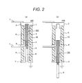
- Fig. 2 1 denotes an electrical contact and 2 denotes a conducting rod, wherein the contact rod 100 has contacts 1 connected by soldering to both ends of the conducting rod 2. The soldering was carried out at 200 °C for 30 minutes in air.
- 3 denotes a closing electrode, 4 a disconnection electrode, and 5 an earth electrode, each being made of oxygen free copper.
- the electrodes 3, 4, 5 have inner diameters, which make a good contact condition with the electrical contact 1.
- the earth electrode 5 is connected to an earth.
- the closing electrode 3, disconnection electrode 4 and earth electrode 5 are assembled in a manner that they are electrically insulated by an ceramic insulating cylinder 6. denotes a main circuit conductor, one end of which is connected to the closing electrode 3 and the disconnection electrode 4, and the other end is connected to an electric power switch device50, as shown in Figs. 3(a) to (d) .
- the air insulated current switch 200 is constituted by the above mentioned components. Contacting spring elements may be provided to inner diameter sides of the closing electrode 3, disconnection electrode 4 and earth electrode 5 so as to secure a good contact condition with the electrical contact.
- Figs. 3 (a) to (d) there are shown operations of the switch systems according to embodiments of the present invention.
- a vacuum valve can be used as the switch device 50.
- Figs. 3(a) and (b) show a closed state of the switch system wherein the closing electrode 3 and the disconnection electrode 4 are connected by means of the contact rod 100.
- Fig. 3(a) shows that current flows through the main circuit.
- Fig. 3(b) shows the main switch device 50 is off by emergency caused by abnormal current, etc.
- Figs. 3 (c) and (d) the disconnection electrode 4 and the earth electrode 5 are connected by means of the contact rod 100.
- Fig. 3 (c) shows a disconnection state for maintenance where the switch system is completely separated for maintenance thereof.
- Fig. 3 (d) shows an earth state where the switch device 50 is closed by mistakes, but the disconnection state of the main circuit is kept.
Landscapes
- Chemical & Material Sciences (AREA)
- Engineering & Computer Science (AREA)
- Composite Materials (AREA)
- Materials Engineering (AREA)
- Contacts (AREA)
- High-Tension Arc-Extinguishing Switches Without Spraying Means (AREA)
Applications Claiming Priority (1)
| Application Number | Priority Date | Filing Date | Title |
|---|---|---|---|
| JP2010031934A JP2011171023A (ja) | 2010-02-17 | 2010-02-17 | 電気接点およびそれを用いた電力開閉器 |
Publications (2)
| Publication Number | Publication Date |
|---|---|
| EP2362400A2 true EP2362400A2 (fr) | 2011-08-31 |
| EP2362400A3 EP2362400A3 (fr) | 2011-10-12 |
Family
ID=44022891
Family Applications (1)
| Application Number | Title | Priority Date | Filing Date |
|---|---|---|---|
| EP11154050A Withdrawn EP2362400A3 (fr) | 2010-02-17 | 2011-02-10 | Contact électrique et dispositif de commutation l'utilisant |
Country Status (3)
| Country | Link |
|---|---|
| EP (1) | EP2362400A3 (fr) |
| JP (1) | JP2011171023A (fr) |
| CN (1) | CN102162043A (fr) |
Families Citing this family (1)
| Publication number | Priority date | Publication date | Assignee | Title |
|---|---|---|---|---|
| JP6382069B2 (ja) * | 2014-10-30 | 2018-08-29 | 株式会社日立産機システム | スイッチギヤ |
Citations (3)
| Publication number | Priority date | Publication date | Assignee | Title |
|---|---|---|---|---|
| JPH09111312A (ja) | 1995-10-13 | 1997-04-28 | Sumitomo Electric Ind Ltd | 複合合金部材の製造方法 |
| JP2003147407A (ja) | 2001-11-08 | 2003-05-21 | Hitachi Ltd | 電気接点部材とその製造法及びそれを用いた真空バルブ並びに真空遮断器 |
| JP2004211192A (ja) | 2003-01-09 | 2004-07-29 | Hitachi Ltd | 真空バルブ用電極、及びそれを用いた真空バルブ,真空遮断器 |
Family Cites Families (11)
| Publication number | Priority date | Publication date | Assignee | Title |
|---|---|---|---|---|
| GB1084351A (fr) * | ||||
| US3184835A (en) * | 1961-10-02 | 1965-05-25 | Handy & Harman | Process for internally oxidationhardening alloys, and alloys and structures made therefrom |
| JPS62200228U (fr) * | 1986-06-10 | 1987-12-19 | ||
| CA2045125A1 (fr) * | 1989-11-09 | 1991-05-10 | Larry E. Mccandlish | Procede de conversion par pulverisation destine a la production de poudres composites nanophases |
| US6103392A (en) * | 1994-12-22 | 2000-08-15 | Osram Sylvania Inc. | Tungsten-copper composite powder |
| JP4249356B2 (ja) * | 1999-12-28 | 2009-04-02 | 株式会社東芝 | 電気接点材料 |
| JP2002327232A (ja) * | 2001-04-27 | 2002-11-15 | Toshiba Corp | 電気接点用複合材料とその製造方法並びに電気開閉装置 |
| KR100446985B1 (ko) * | 2001-11-20 | 2004-09-01 | 학교법인 한양학원 | W-Cu복합 분말의 제조방법 |
| TW200425192A (en) * | 2003-01-09 | 2004-11-16 | Hitachi Ltd | Electrode for vacuum interrupter, vacuum interrupter using the same and vacuum circuit-breaker |
| FR2877136B1 (fr) * | 2004-10-27 | 2006-12-15 | Areva T & D Sa | Cinematique d'entrainement dans un disjoncteur hybride |
| KR100740801B1 (ko) * | 2005-05-02 | 2007-07-19 | 정운태 | 패널변압기 내장형 배전반 |
-
2010
- 2010-02-17 JP JP2010031934A patent/JP2011171023A/ja active Pending
-
2011
- 2011-02-10 EP EP11154050A patent/EP2362400A3/fr not_active Withdrawn
- 2011-02-16 CN CN 201110040134 patent/CN102162043A/zh active Pending
Patent Citations (3)
| Publication number | Priority date | Publication date | Assignee | Title |
|---|---|---|---|---|
| JPH09111312A (ja) | 1995-10-13 | 1997-04-28 | Sumitomo Electric Ind Ltd | 複合合金部材の製造方法 |
| JP2003147407A (ja) | 2001-11-08 | 2003-05-21 | Hitachi Ltd | 電気接点部材とその製造法及びそれを用いた真空バルブ並びに真空遮断器 |
| JP2004211192A (ja) | 2003-01-09 | 2004-07-29 | Hitachi Ltd | 真空バルブ用電極、及びそれを用いた真空バルブ,真空遮断器 |
Also Published As
| Publication number | Publication date |
|---|---|
| EP2362400A3 (fr) | 2011-10-12 |
| JP2011171023A (ja) | 2011-09-01 |
| CN102162043A (zh) | 2011-08-24 |
Similar Documents
| Publication | Publication Date | Title |
|---|---|---|
| JP4979604B2 (ja) | 真空バルブ用電気接点 | |
| US7704449B2 (en) | Electrode, electrical contact and method of manufacturing the same | |
| US8183489B2 (en) | Contact element | |
| US10804044B2 (en) | Electrical contact alloy for vacuum contactors | |
| US3385677A (en) | Sintered composition material | |
| CN101911236A (zh) | 真空断路器的电极接点部件及其制造方法 | |
| CN104377046A (zh) | 包括触头尖端的系统 | |
| EP3062327A1 (fr) | Contact électrique pour soupape de dépression et son procédé de fabrication | |
| EP2323148A1 (fr) | Contact électrique et interrupteur d'aspirateur l'utilisant | |
| JP3428416B2 (ja) | 真空遮断器及びそれに用いる真空バルブと電気接点並びに製造方法 | |
| US4919717A (en) | Sintered composite material for electrical contact | |
| EP2362400A2 (fr) | Contact électrique et dispositif de commutation l'utilisant | |
| EP2161728A2 (fr) | Contacts électriques et leurs procédés de fabrication, et appareil de commutation pour énergie électrique | |
| US20060169370A1 (en) | Electrical contact material and method for making same | |
| CN102308353B (zh) | 真空阀用电触点及使用其的真空断路器 | |
| JPH1150177A (ja) | 真空遮断器用接点材料,その製造方法および真空遮断器 | |
| JP2008021590A (ja) | 真空バルブ用電気接点とその製法、真空バルブ用電極、真空バルブ及び真空遮断器 | |
| JP2003183749A (ja) | 真空遮断器用接点材料および真空遮断器 | |
| JP2002161327A (ja) | 遮断器用接点材料,その製造方法および遮断器 | |
| JP2001319550A (ja) | 真空バルブ用の接点材,真空バルブ用の接点材の製造方法および真空バルブ | |
| JP2011014240A (ja) | 真空バルブ用電気接点およびそれを用いた真空開閉機器 | |
| JPH056291B2 (fr) |
Legal Events
| Date | Code | Title | Description |
|---|---|---|---|
| PUAI | Public reference made under article 153(3) epc to a published international application that has entered the european phase |
Free format text: ORIGINAL CODE: 0009012 |
|
| 17P | Request for examination filed |
Effective date: 20110601 |
|
| AK | Designated contracting states |
Kind code of ref document: A2 Designated state(s): AL AT BE BG CH CY CZ DE DK EE ES FI FR GB GR HR HU IE IS IT LI LT LU LV MC MK MT NL NO PL PT RO RS SE SI SK SM TR |
|
| AX | Request for extension of the european patent |
Extension state: BA ME |
|
| PUAL | Search report despatched |
Free format text: ORIGINAL CODE: 0009013 |
|
| AK | Designated contracting states |
Kind code of ref document: A3 Designated state(s): AL AT BE BG CH CY CZ DE DK EE ES FI FR GB GR HR HU IE IS IT LI LT LU LV MC MK MT NL NO PL PT RO RS SE SI SK SM TR |
|
| AX | Request for extension of the european patent |
Extension state: BA ME |
|
| RIC1 | Information provided on ipc code assigned before grant |
Ipc: H01H 1/0237 20060101ALN20110907BHEP Ipc: H01H 1/025 20060101AFI20110907BHEP |
|
| 17Q | First examination report despatched |
Effective date: 20121205 |
|
| STAA | Information on the status of an ep patent application or granted ep patent |
Free format text: STATUS: THE APPLICATION IS DEEMED TO BE WITHDRAWN |
|
| 18D | Application deemed to be withdrawn |
Effective date: 20130416 |