EP2362429A2 - Montage de réseau de module encadré photovoltaïque à l'aide d'un rail asymétrique - Google Patents
Montage de réseau de module encadré photovoltaïque à l'aide d'un rail asymétrique Download PDFInfo
- Publication number
- EP2362429A2 EP2362429A2 EP11155460A EP11155460A EP2362429A2 EP 2362429 A2 EP2362429 A2 EP 2362429A2 EP 11155460 A EP11155460 A EP 11155460A EP 11155460 A EP11155460 A EP 11155460A EP 2362429 A2 EP2362429 A2 EP 2362429A2
- Authority
- EP
- European Patent Office
- Prior art keywords
- framed
- module
- rail
- capture
- slot
- Prior art date
- Legal status (The legal status is an assumption and is not a legal conclusion. Google has not performed a legal analysis and makes no representation as to the accuracy of the status listed.)
- Withdrawn
Links
- 238000000034 method Methods 0.000 claims description 14
- 230000008878 coupling Effects 0.000 claims description 3
- 238000010168 coupling process Methods 0.000 claims description 3
- 238000005859 coupling reaction Methods 0.000 claims description 3
- 230000000284 resting effect Effects 0.000 claims description 2
- 238000009434 installation Methods 0.000 description 20
- 230000008901 benefit Effects 0.000 description 4
- 230000007246 mechanism Effects 0.000 description 4
- 238000003780 insertion Methods 0.000 description 3
- 230000037431 insertion Effects 0.000 description 3
- 230000009467 reduction Effects 0.000 description 3
- 238000003491 array Methods 0.000 description 2
- 238000004519 manufacturing process Methods 0.000 description 2
- 238000012986 modification Methods 0.000 description 2
- 230000004048 modification Effects 0.000 description 2
- CYJRNFFLTBEQSQ-UHFFFAOYSA-N 8-(3-methyl-1-benzothiophen-5-yl)-N-(4-methylsulfonylpyridin-3-yl)quinoxalin-6-amine Chemical compound CS(=O)(=O)C1=C(C=NC=C1)NC=1C=C2N=CC=NC2=C(C=1)C=1C=CC2=C(C(=CS2)C)C=1 CYJRNFFLTBEQSQ-UHFFFAOYSA-N 0.000 description 1
- 230000004308 accommodation Effects 0.000 description 1
- 230000004888 barrier function Effects 0.000 description 1
- 238000013461 design Methods 0.000 description 1
- 238000009429 electrical wiring Methods 0.000 description 1
- 230000007717 exclusion Effects 0.000 description 1
- 238000005259 measurement Methods 0.000 description 1
- 239000003607 modifier Substances 0.000 description 1
- 230000008569 process Effects 0.000 description 1
- 230000008439 repair process Effects 0.000 description 1
Images






Classifications
-
- H—ELECTRICITY
- H02—GENERATION; CONVERSION OR DISTRIBUTION OF ELECTRIC POWER
- H02S—GENERATION OF ELECTRIC POWER BY CONVERSION OF INFRARED RADIATION, VISIBLE LIGHT OR ULTRAVIOLET LIGHT, e.g. USING PHOTOVOLTAIC [PV] MODULES
- H02S20/00—Supporting structures for PV modules
-
- F—MECHANICAL ENGINEERING; LIGHTING; HEATING; WEAPONS; BLASTING
- F24—HEATING; RANGES; VENTILATING
- F24S—SOLAR HEAT COLLECTORS; SOLAR HEAT SYSTEMS
- F24S25/00—Arrangement of stationary mountings or supports for solar heat collector modules
- F24S25/30—Arrangement of stationary mountings or supports for solar heat collector modules using elongate rigid mounting elements extending substantially along the supporting surface, e.g. for covering buildings with solar heat collectors
- F24S25/33—Arrangement of stationary mountings or supports for solar heat collector modules using elongate rigid mounting elements extending substantially along the supporting surface, e.g. for covering buildings with solar heat collectors forming substantially planar assemblies, e.g. of coplanar or stacked profiles
- F24S25/35—Arrangement of stationary mountings or supports for solar heat collector modules using elongate rigid mounting elements extending substantially along the supporting surface, e.g. for covering buildings with solar heat collectors forming substantially planar assemblies, e.g. of coplanar or stacked profiles by means of profiles with a cross-section defining separate supporting portions for adjacent modules
-
- F—MECHANICAL ENGINEERING; LIGHTING; HEATING; WEAPONS; BLASTING
- F24—HEATING; RANGES; VENTILATING
- F24S—SOLAR HEAT COLLECTORS; SOLAR HEAT SYSTEMS
- F24S25/00—Arrangement of stationary mountings or supports for solar heat collector modules
- F24S25/60—Fixation means, e.g. fasteners, specially adapted for supporting solar heat collector modules
- F24S25/61—Fixation means, e.g. fasteners, specially adapted for supporting solar heat collector modules for fixing to the ground or to building structures
-
- H—ELECTRICITY
- H02—GENERATION; CONVERSION OR DISTRIBUTION OF ELECTRIC POWER
- H02S—GENERATION OF ELECTRIC POWER BY CONVERSION OF INFRARED RADIATION, VISIBLE LIGHT OR ULTRAVIOLET LIGHT, e.g. USING PHOTOVOLTAIC [PV] MODULES
- H02S30/00—Structural details of PV modules other than those related to light conversion
- H02S30/10—Frame structures
-
- Y—GENERAL TAGGING OF NEW TECHNOLOGICAL DEVELOPMENTS; GENERAL TAGGING OF CROSS-SECTIONAL TECHNOLOGIES SPANNING OVER SEVERAL SECTIONS OF THE IPC; TECHNICAL SUBJECTS COVERED BY FORMER USPC CROSS-REFERENCE ART COLLECTIONS [XRACs] AND DIGESTS
- Y02—TECHNOLOGIES OR APPLICATIONS FOR MITIGATION OR ADAPTATION AGAINST CLIMATE CHANGE
- Y02E—REDUCTION OF GREENHOUSE GAS [GHG] EMISSIONS, RELATED TO ENERGY GENERATION, TRANSMISSION OR DISTRIBUTION
- Y02E10/00—Energy generation through renewable energy sources
- Y02E10/40—Solar thermal energy, e.g. solar towers
- Y02E10/47—Mountings or tracking
-
- Y—GENERAL TAGGING OF NEW TECHNOLOGICAL DEVELOPMENTS; GENERAL TAGGING OF CROSS-SECTIONAL TECHNOLOGIES SPANNING OVER SEVERAL SECTIONS OF THE IPC; TECHNICAL SUBJECTS COVERED BY FORMER USPC CROSS-REFERENCE ART COLLECTIONS [XRACs] AND DIGESTS
- Y02—TECHNOLOGIES OR APPLICATIONS FOR MITIGATION OR ADAPTATION AGAINST CLIMATE CHANGE
- Y02E—REDUCTION OF GREENHOUSE GAS [GHG] EMISSIONS, RELATED TO ENERGY GENERATION, TRANSMISSION OR DISTRIBUTION
- Y02E10/00—Energy generation through renewable energy sources
- Y02E10/50—Photovoltaic [PV] energy
-
- Y—GENERAL TAGGING OF NEW TECHNOLOGICAL DEVELOPMENTS; GENERAL TAGGING OF CROSS-SECTIONAL TECHNOLOGIES SPANNING OVER SEVERAL SECTIONS OF THE IPC; TECHNICAL SUBJECTS COVERED BY FORMER USPC CROSS-REFERENCE ART COLLECTIONS [XRACs] AND DIGESTS
- Y10—TECHNICAL SUBJECTS COVERED BY FORMER USPC
- Y10T—TECHNICAL SUBJECTS COVERED BY FORMER US CLASSIFICATION
- Y10T29/00—Metal working
- Y10T29/49—Method of mechanical manufacture
- Y10T29/49002—Electrical device making
Definitions
- the subject matter disclosed herein relates generally to photovoltaic modules, and more specifically to mounting structures and methods applicable to framed photovoltaic module arrays.
- Photovoltaic systems offer a clean and renewable source of energy. Critical factors in usage and adoption of photovoltaic cells as a supplementary or primary power source include cost to end users and ease of installation. In residential environments, photovoltaic modules are typically installed on house roofs or other suitable surfaces providing optimal exposure to sunlight during the day.
- Photovoltaic modules typically requires elaborate fitting equipment and installation procedures. A significant number of parts are required for a complete installation of a residential photovoltaic module array with one commercially available system including up to 700 different parts for installation of a two row array having twenty four framed modules. Manufacturing costs and installation costs increase significantly as the number of parts is increased. Such costs are a barrier to widespread usage and adoption of photovoltaic cells as power sources.
- a photovoltaic framed module array apparatus for mounting a first framed photovoltaic (PV) module and a second framed PV module, comprises a first rail.
- the first rail includes an insert slot for accommodating an insert edge of the first framed PV module, and a capture slot for accommodating a capture edge of the second framed PV module.
- the capture slot is positioned substantively parallel to the insert slot.
- a method for assembling a photovoltaic framed module array includes inserting an insert edge of a first framed photovoltaic (PV) module into an insert slot of a first rail, placing a capture edge of the first framed PV module into a capture slot of a second rail, and securing the first framed PV module to the second rail.
- the first framed PV module is rigidly secured between the first rail and the second rail.
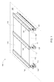
- FIG. 1 is a perspective view of a framed module array according to an embodiment of the invention.
- FIG. 2 is a perspective view of a section of a rail according to an embodiment of the invention.
- FIG. 3 is a perspective view of the rail of FIG. 2 with a mounting interface.
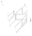
- FIG. 4 is a perspective view of a section of a rail according to another embodiment of the invention.
- FIG. 5 is a perspective view of the rail of FIG. 4 with a mounting interface.
- FIG. 6 is a front view of multiple steps involved in the insert and capture of a framed module for creating a framed module array, according to an embodiment of the present invention.
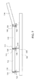
- FIG. 7 is a front view of multiple framed modules assembled adjacently, according to an embodiment of the present invention.
- FIG. 8 is a framed module array comprising electric wire connections, according to another embodiment of the present invention.
- FIG. 9 is a schematic representation of the electrical wiring in the framed module array of FIG. 8 .
- FIG. 1 illustrates a framed photovoltaic module array apparatus 100 according to an embodiment of the present invention.
- the framed photovoltaic module array apparatus 100 is mounted on a base support 140, such as a roof, ground, or any other rigid support.
- the framed photovoltaic module array apparatus 100 includes multiple framed photovoltaic modules (first) 110, (second) 112, (third) 116, (fourth) 118 installed using rails (first) 120, (second) 122, (third) 124 and clamps (first) 130, (second) 132, (third) 134 to form the framed photovoltaic module array apparatus 100.
- Each of the framed modules, for example 110, 112 have a capture edge 109, 113 and an insert edge 111, 115 respectively.
- the first framed module 110 and the second framed module 112 are assembled on to either sides of the rail 120 and aligned in a parallel orientation, which is referred to as a "parallel and across the rail" configuration for the purpose of this discussion.
- the first framed module 110 is assembled sequentially or adjacently with the third framed module 116, on to the same side of the rail 120, which is referred to as an "adjacent and on the same side of the rail" configuration for the purpose of this discussion.
- the framed modules e.g. 110, 112
- the framed modules have a rectangular cross section.
- the framed modules are configured to accommodate various shapes of the edges of the framed modules.
- FIG. 2 illustrates a section 200 of the rail 120 of FIG. 1 according to an embodiment of the invention.
- the rail 120 includes an insert slot 210, a capture slot 220, a clamp slot 230, a mounting interface 240, and a cavity 250.
- the insert slot 210 and the capture slot 220 are positioned at opposite sides of the rail allowing disposition of multiple parallel rails to support multiple module rows therebetween. Therefore, the insert slot 210 and the capture slot 220 are positioned on opposing sides of the rail 120, and configured to accommodate different framed modules on the opposing sides such as, for example, the framed modules 110 and 112 respectively in FIG. 1 . For example, this configuration allows three rails to support two full rows of modules.
- the cavity 250 separates the insert slot 210 and the capture slot 220.
- the cavity 250 may be filled up, and hence there may not be a cavity.
- the cavity 250 if present, according to certain contemplated embodiments, provides a channel for photovoltaic system utilities, for example, wires, cables, drainage channels and the like.
- the clamp slot 230 is positioned above the cavity 250, and the mounting interface 240 extends below from the bottom of the cavity 250.
- the rail 120 has an asymmetrical shape to allow for insert and capture of framed photovoltaic modules.
- the opposite side of the rail 120 is configured to accommodate an opposite edge of another framed photovoltaic module and provide for clamping of the opposite edge, thereby capturing the edge.
- clamping provides mechanical restriction of the module within the capture slot of the rail, and the clamp may be affixed or padlocked to deter module theft. Further such mechanical restriction may be attained using any other well known mechanisms, and all such mechanisms are included within the scope and spirit of the present invention.
- the two sides of the rail 120 have a different shape and configuration to suit different purposes, and therefore and asymmetric configuration of the rail 120, advantageously provides for the insert and capture of framed PV modules.
- similar shapes embodying the general principles discussed herein may be devised, and all such obvious shape and form variations are included within the scope and spirit of the present invention.
- the insert slot 210 accommodates an insert edge of a framed module, for example the insert edge 111 of the framed module 110. Accordingly, the insert slot 210 provides a rigid receptacle (or a channel) with a side boundary 212 bound within an upper boundary 214 and a lower boundary 216. In the illustrated embodiment, the insert slot 210 defines an angular "C" shape to match closely, the profile of the insert edge of the framed module (e.g. the framed module 110) having a similar angular "C" shape profile.
- the insert slot 210 may be sized to provide a receptacle shape to match the profile of the insert edges, in general, and provide a substantively close fit and ease in insertion of the insert edge of the framed modules into the insert slot 210.
- Capture slot 220 accommodates a capture edge of a framed module that is different than the framed module captured by the insert slot 210 such as, for example the capture edge 115 of the second framed module 112 of FIG. 1 .
- the capture slot 220 includes a side boundary 222, and a lower boundary 224 (e.g. a ledge) projecting normally out of the vertical boundary 222 at the bottom end of the vertical boundary 222.
- the side boundary 222 of the capture slot 220 and the side boundary 212 of the insert slot 210 are aligned to be parallel, however, the lower boundary 224 of the capture slot 220 projects in an opposite direction to the upper and lower boundaries (214 and 216 respectively) of the insert slot 210.
- the lower boundary 224 and the lower boundary 216 project out at substantively the same height within the rail 120, and, for ease of mounting, the vertical boundary 222 is shorter than the vertical boundary 212.
- the clamp slot 230 provides accommodation for a clamp (for example the clamp 130 of FIG. 1 ) configured to clamp a capture edge of a framed module to the rail 120, for example the capture edge 115 of the second framed module 112.
- the clamp slot 230 is a substantively horizontal platform on to which the clamp 130 may be removably attached. While in the illustrated embodiments the clamp 130 is mechanically fastened on to the clamp slot 230, those skilled in the art will readily appreciate alternate attaching mechanisms for attaching or removably attaching the clamp 130 on to the clamp slot 230 may be used equivalently.
- the clamp slot 230 is positioned to be between the vertical boundary 212 and the vertical boundary 222. At least a portion of the vertical boundary 212 (the portion exceeding the height of the vertical boundary 222, for example) defines an edge of the clamp slot 230.
- the mounting interface 240 provides a rigid interface for the rail 120 with a base support, for example similar to the base support 140 of FIG. 1 .
- the mounting interface 240 includes a T-bolt slot 242.
- FIG. 3 illustrates a section 300 of the rail 120 in a bolted configuration with a mounting hardware. More specifically, a T-bolt 310 is inserted into the T-bolt slot 242 provided in the mounting interface. The T-bolt 310 bolts a bracket 320 to the rail 120 in a removably attached (rigid interface) configuration.
- FIGS. 4 and 5 illustrate a rail 400 according to another embodiment of the present invention.
- the mounting interface 440 of the rail 400 provides a rigid interface for the rail 400 with a base support using a bolt (or another mechanical fastener) 510 and a roof attachment 520 (e.g a stanchion), such as those generally known in the art, and for example, the roof attachment illustrated by FIG. 5 .
- a bolt or another mechanical fastener
- a roof attachment 520 e.g a stanchion
- FIG. 4 and 5 provide alternative geometry to the base of the rail for mounting.
- Various similar mounting mechanisms will appear readily to those skilled in the art, and all such obvious variations are included within the scope and spirit of the present invention.
- FIG. 6 illustrates a technique for installation of the photovoltaic framed module array apparatus 100.
- installation of the framed module 110 using the rails 120 and 122 is illustrated.
- the insert edge 109 of the framed module 110 is inserted in to the insert slot of the rail 120.
- the capture edge 111 of the framed module 110 is then allowed to come to rest on to the capture slot of the rail 122, while the insert edge 109 fits cleanly in to the insert slot of the rail 120.
- the insert and capture slots within the various rails 120, 122, 124) are configured at substantively the same height within each rail, and the framed module 110 is held at a substantively similar height from the base of the first and second rails 120, 122.
- the capture edge 111 of the framed module 110 is then captured on to the rail 122 using a clamp 130.
- the clamp 130 is screwed onto the clamp slot of the rail 122, for example, as illustrated by the figures.
- the rails 120 and 122 are identical, however, in other configurations, for example, in which a rail is at an edge of the array 100, the rail at the edge may include only a subset of the features (e.g. only the capture slot, or only the insert slot, depending on the location within the photovoltaic framed module array apparatus 100) of the other rails, for example, the rail 120 of FIGS. 1 and 2 .
- the framed module 110 represents a row of framed modules installed along the rails 120 and 122, for example, framed modules 110 and 116 of FIG. 1 , in an adjacent and on the same side of the rail configuration. Rows of framed modules (represented by the framed module 114) may be added similarly across each rail, for example, the rail 122, to scale the apparatus 100 as required. For example, a row of framed module represented by the framed module 112 is included between the rails 120 and 124.
- the insert slots and the capture slots of the rails are configured to accommodate the first framed PV module 110 and the second framed PV module 112 at substantively the same level, so as to provide a substantially continuous surface across the rails (e.g. the rail 120 and/or the rail 124) within the apparatus 100.
- Each of the framed PV modules (110, 112, 114) illustrated in FIG. 7 represents a row of framed modules.
- the framed PV module 110, mounted on the rails 120, 122 on either side represents a row having multiple other PV framed modules mounted on the rails 120, 122, for example, behind the framed PV module 110.
- n-1 rails to support n rows of framed PV modules, where n is a natural number representing the number of rows of framed PV modules.
- n is a natural number representing the number of rows of framed PV modules.
- the number of rails required is two (2), which does not follow the formula of 2n-1.
- the insert and capture functionality afforded by the photovoltaic framed module array apparatus 100 simplifies the installation procedure significantly, and reduces the need for a highly skilled laborer for installation, directly reducing the cost and the time required for installation.
- the modular nature of the photovoltaic framed module array apparatus 100 provides easy scalability for larger apparatus installations.
- the disclosed embodiments further utilize a lesser number of components, for example, in one embodiment, only about 400 parts are required for an array having two rows and twenty four photovoltaic framed modules, offering reduction in the number of parts by over 40 percent. The reduction in the number of parts provides a reduction in manufacturing costs and installation costs.
- the disclosed embodiments allow for an advantage in ease of repairability, since it is very easy to remove any module form the insert and capture slots, for example, in order to repair and/or replace the modules. It is appreciated here that the disclosed embodiments provide significant cost, complexity and time advantages in the installation of photovoltaic framed module arrays, thereby making the use of photovoltaic cells as sources of energy easier and more cost effective for the end user.
- FIGS. 8 and 9 illustrate a photovoltaic framed module array apparatus 800 including electrical fittings according another embodiment of the present invention.
- the photovoltaic module array apparatus 800 allows for plug and play of PV modules, and eliminates the need for substantive wiring at the time of installation of PV module systems or apparatus, as illustrated.
- the apparatus 800 includes a first framed module 810 and a second framed module 816 in an adjacent and on the same side of the rail configuration, between a first rail 820 and a second rail 822.
- the framed modules 810, 816 each include a first electric wiring 824 and a second electric wiring 826, respectively, within the body of the respective framed modules 810, 816.
- Each framed module 810, 816 further includes, respectively, a first electric connector jack 830 and a second electric connector jack 832.
- the first jack 830 and the second jack 832 is configured to couple electrically with a single insert operation, such as those generally known in the art. Several other such coupling configurations of the jack will occur to those skilled in the art, and are included within the scope and spirit of the present invention.
- the first framed module 810 is already mounted on the rails 820 and 822, and the second framed module 816 is inserted into the rail 820 and captured on to the rail 822.
- the second framed module 816 is mounted onto the rails 820, 822 such that a gap exists between the first framed module 810 and the second framed module 816. As further illustrated in FIG. 8 , the second framed module 816 is slid towards the first framed module 810 to mate with the first framed module 810. In the process, the first electric connector jack 830 of the first framed module 810 automatically mates (electrically couples) with the second electric connector jack 832 of the second framed module 816.
- the easy installation provide by the insert and capture feature of the apparatus 100 is leveraged by the apparatus 800 to further include electrical connectivity across framed modules using a single, simple operation, further reducing the complexity, number of different parts, number of operations required to install, and the time required to install the apparatus.
- the insert and capture techniques as discussed with respect to various embodiments discussed herein forwards the opportunity to slide the modules for plug and play.
- the arrangement as discussed allows for removal of most, if not all, extraneous wiring.
- FIG. 9 is a schematic illustration of electric wiring configuration within two adjacent photovoltaic modules of FIG. 8 , the first framed module 810 and the second framed module 816, each having a frame 902 and 904 respectively.
- Each of the modules (810, 816) has a first junction box 910 and a second junction box 920, respectively, that provides the wiring external to the module, necessary for the electrical series connection of adjacent modules.
- two wires (912, 914) extend from the first junction box 910 in the first framed module 810
- two wires (922, 924) extend from the second junction box 920 in the second framed module 816.
- the full open circuit voltage potential of each module appears across these wires, e.g.
- each module the wires terminate into connector jacks 830 and 832, that are integrated into the framed modules frames (902, 904) respectively.
- the connector jacks 830 and 832 positioned on opposite but facing sides of each module are female and male configured connectors, respectively, and each connector (830, 832) has two connection pins each (932, 934 and 942, 944 respectively).
- one pin of each connector is joined to the power wire from a junction box and the second pin is electrically connected to the frames of the modules 902 and 904 for providing the ground connections.
- grounding wire which is conventionally installed separately during installation of the PV module systems, advantageously, does not need to be installed in accordance with the illustrated embodiment.
- the ground wire is, for example, incorporated in the wiring of the plug and play embodiment illustrated by FIGS. 8 and 9 .
- front is merely used for convenience of description, and are not limited to any one position or spatial orientation. It is also appreciated that the format can be portrait or landscape as defined by which opposite edges form the insert and capture sides, the long or short sides of the module.
- the modifier "about” used in connection with a quantity is inclusive of the stated value and has the meaning dictated by the context (e.g., includes the degree of error associated with measurement of the particular quantity).
Landscapes
- Engineering & Computer Science (AREA)
- Chemical & Material Sciences (AREA)
- Life Sciences & Earth Sciences (AREA)
- Sustainable Development (AREA)
- Sustainable Energy (AREA)
- Thermal Sciences (AREA)
- Physics & Mathematics (AREA)
- Combustion & Propulsion (AREA)
- Mechanical Engineering (AREA)
- General Engineering & Computer Science (AREA)
- Photovoltaic Devices (AREA)
- Roof Covering Using Slabs Or Stiff Sheets (AREA)
- Connector Housings Or Holding Contact Members (AREA)
Applications Claiming Priority (1)
| Application Number | Priority Date | Filing Date | Title |
|---|---|---|---|
| US12/713,894 US8595996B2 (en) | 2010-02-26 | 2010-02-26 | Photovoltaic framed module array mount utilizing asymmetric rail |
Publications (1)
| Publication Number | Publication Date |
|---|---|
| EP2362429A2 true EP2362429A2 (fr) | 2011-08-31 |
Family
ID=44246369
Family Applications (1)
| Application Number | Title | Priority Date | Filing Date |
|---|---|---|---|
| EP11155460A Withdrawn EP2362429A2 (fr) | 2010-02-26 | 2011-02-22 | Montage de réseau de module encadré photovoltaïque à l'aide d'un rail asymétrique |
Country Status (4)
| Country | Link |
|---|---|
| US (1) | US8595996B2 (fr) |
| EP (1) | EP2362429A2 (fr) |
| CN (1) | CN102194905A (fr) |
| AU (1) | AU2011200845A1 (fr) |
Cited By (8)
| Publication number | Priority date | Publication date | Assignee | Title |
|---|---|---|---|---|
| US20110209745A1 (en) * | 2010-02-26 | 2011-09-01 | General Electric Company | Photovoltaic framed module array mount utilizing asymmetric rail |
| CN107717370A (zh) * | 2017-09-19 | 2018-02-23 | 合肥流明新能源科技有限公司 | 一种提高光伏组件装框精度的装置及其使用方法 |
| WO2021009406A1 (fr) * | 2019-07-16 | 2021-01-21 | Soltec Innovations, S.L. | Connecteur de support, connecteur de panneau solaire couplable au connecteur de support et système de connexion qui comprend ledit connecteur de support et ledit connecteur de panneau solaire |
| US11245354B2 (en) | 2018-07-31 | 2022-02-08 | Tesla, Inc. | Solar roof tile spacer with embedded circuitry |
| US11245355B2 (en) * | 2018-09-04 | 2022-02-08 | Tesla, Inc. | Solar roof tile module |
| US11258398B2 (en) | 2017-06-05 | 2022-02-22 | Tesla, Inc. | Multi-region solar roofing modules |
| US11437534B2 (en) | 2018-02-20 | 2022-09-06 | Tesla, Inc. | Inter-tile support for solar roof tiles |
| EP4213378A4 (fr) * | 2020-09-07 | 2024-11-13 | Hengdian Group DMEGC Magnetics Co., Ltd. | Structure d'installation d'un ensemble photovoltaïque et son procédé de mise en oeuvre |
Families Citing this family (84)
| Publication number | Priority date | Publication date | Assignee | Title |
|---|---|---|---|---|
| US7434362B2 (en) * | 2001-07-20 | 2008-10-14 | Unirac, Inc. | System for removably and adjustably mounting a device on a surface |
| US7600349B2 (en) * | 2003-02-26 | 2009-10-13 | Unirac, Inc. | Low profile mounting system |
| CA2681970C (fr) * | 2007-03-30 | 2013-09-24 | Haticon Gmbh | Fixation pour modules solaires |
| DE202008017629U1 (de) * | 2008-09-03 | 2010-04-22 | Sapa Gmbh | Solarmodulrahmen mit Wasserablauf |
| US10277159B2 (en) | 2008-11-17 | 2019-04-30 | Kbfx Llc | Finished multi-sensor units |
| FR2938566B1 (fr) * | 2008-11-17 | 2012-01-13 | Alain Poivet | Dispositif de support de panneaux de cellules photovoltaiques et systeme de support de panneaux photovoltaiques |
| US11063553B2 (en) | 2008-11-17 | 2021-07-13 | Kbfx Llc | Solar carports, solar-tracking carports, and methods |
| US8919053B2 (en) * | 2009-07-02 | 2014-12-30 | Zep Solar, Llc | Leveling foot apparatus, system, and method for photovoltaic arrays |
| US8511006B2 (en) | 2009-07-02 | 2013-08-20 | Owens Corning Intellectual Capital, Llc | Building-integrated solar-panel roof element systems |
| US8695290B1 (en) * | 2009-12-07 | 2014-04-15 | Ironridge, Inc. | Systems and methods for splicing solar panel racks |
| US10054336B2 (en) | 2010-03-03 | 2018-08-21 | Robert M. M. Haddock | Photovoltaic module mounting assembly |
| DE202010006442U1 (de) * | 2010-05-04 | 2010-08-19 | Ideematec Deutschland Gmbh | Gestell zur Befestigung von Solarmodulen |
| FR2961300B1 (fr) * | 2010-06-14 | 2014-05-09 | Inst Rech Fondamentale En Technologies Solaires Irfts | Structure de solidarisation de panneaux photovoltaiques sur un bati |
| US20120073630A1 (en) * | 2010-09-28 | 2012-03-29 | Perfect Source Technology Corp. | Rectangular protective frame for solar cell module |
| US9611652B2 (en) | 2011-02-25 | 2017-04-04 | Dustin M. M. Haddock | Mounting device for building surfaces having elongated mounting slot |
| US9157665B2 (en) * | 2011-03-15 | 2015-10-13 | Richard William Erickson | Unitized photovoltaic assembly |
| US20140007926A1 (en) * | 2011-04-05 | 2014-01-09 | General Electric Company | Photovoltaic grounding system and method of making same |
| US8782972B2 (en) | 2011-07-14 | 2014-07-22 | Owens Corning Intellectual Capital, Llc | Solar roofing system |
| US20130139870A1 (en) * | 2011-12-02 | 2013-06-06 | Cooper Technologies Company | Pier connection sytem for pier caps of photovoltaic system |
| USD744667S1 (en) * | 2011-12-19 | 2015-12-01 | Exterior Wall Systems Ltd. | Panel attachment extrusion with key |
| WO2013101597A1 (fr) | 2011-12-29 | 2013-07-04 | Haddock Dustin M M | Dispositif de montage pour panneaux à joints debout |
| TWI425646B (zh) * | 2012-01-06 | 2014-02-01 | Au Optronics Corp | 光伏陣列系統、其光伏裝置及其光伏裝置的側框件 |
| WO2013119555A2 (fr) * | 2012-02-06 | 2013-08-15 | First Solar, Inc. | Pince de fixation et configuration de pince de fixation pour installation de module photovoltaïque |
| US20130255751A1 (en) * | 2012-03-30 | 2013-10-03 | General Electric Company | Common solar-thermal electric system and method for assembling |
| US9299868B2 (en) | 2012-10-01 | 2016-03-29 | Marc M. Thomas | Solar panel mounting and installation |
| US10256766B2 (en) | 2012-10-01 | 2019-04-09 | Marc M. Thomas | Solar panel installation and dimension compensating retention device |
| US9038324B2 (en) * | 2013-02-26 | 2015-05-26 | United Construction Products, Inc. | Field paver connector and restraining system |
| US9147785B2 (en) | 2013-03-15 | 2015-09-29 | Robert M. M. Haddock | Slide fit mounting clip for installing photovoltaic modules |
| US8935893B2 (en) * | 2013-05-31 | 2015-01-20 | Sunmodo Corporation | Direct rooftop mounting apparatus for solar panels |
| JP6449152B2 (ja) * | 2013-07-19 | 2019-01-09 | ソーラーフロンティア株式会社 | 太陽電池モジュールの固定装置及び固定方法 |
| US9515599B2 (en) * | 2013-09-17 | 2016-12-06 | Lumos Lsx, Llc | Photovoltaic panel mounting rail with integrated electronics |
| US9097443B2 (en) * | 2013-10-15 | 2015-08-04 | Sunmodo Corporation | Solar panel rooftop mounting and grounding device |
| USD750544S1 (en) * | 2014-05-15 | 2016-03-01 | Edscha Trailer Systems Gmbh | Guide rails for a tarpaulin cover of a commercial vehicle |
| USD753576S1 (en) * | 2014-05-15 | 2016-04-12 | Edscha Trailer Systems Gmbh | Guide rails for a tarpaulin cover of a commercial vehicle |
| USD751024S1 (en) * | 2014-05-15 | 2016-03-08 | Edscha Trailer Systems Gmbh | Guide rails for a tarpaulin cover of a commercial vehicle |
| US11368005B2 (en) | 2014-11-19 | 2022-06-21 | Ironridge, Inc. | Wire management structure for a rail-less solar panel assembly |
| US9647433B2 (en) | 2014-11-19 | 2017-05-09 | Ironridge, Inc. | Rail-less solar panel assembly and installation method |
| US9800199B2 (en) | 2014-11-19 | 2017-10-24 | Ironridge, Inc. | Roof attachment assembly for solar panels and installation method |
| WO2017066666A1 (fr) * | 2015-10-16 | 2017-04-20 | Hubbell Incorporated | Luminaire modulaire à très grande hauteur |
| US12294332B2 (en) | 2015-12-15 | 2025-05-06 | Kbfx Llc | Solar carports, solar-tracking carports, and methods |
| US10110160B2 (en) | 2016-01-11 | 2018-10-23 | Solarcity Corporation | Three-directional photovoltaic module connector |
| WO2018023016A1 (fr) | 2016-07-29 | 2018-02-01 | Haddock Dustin M M | Support de montage sur nervure trapézoidale à pattes flexibles |
| WO2018039288A1 (fr) * | 2016-08-23 | 2018-03-01 | Giga Solar Fpc, Inc. | Systèmes de montage de module solaire améliorés au moyen d'un connecteur de module et procédés associés |
| USD843932S1 (en) * | 2016-09-13 | 2019-03-26 | Orion Solar Racking, Inc. | Solar panel mounting bracket |
| WO2018081722A1 (fr) | 2016-10-31 | 2018-05-03 | Haddock Dustin M M | Pince de liaison électrique de panneaux métalliques |
| US10371185B2 (en) | 2017-01-09 | 2019-08-06 | David Lynn | Magnetically-controlled connectors and methods of use |
| USD826692S1 (en) | 2017-01-31 | 2018-08-28 | Exterior Wall Systems Limited | Four-way cube connector for wall panel system |
| US10036156B1 (en) | 2017-01-31 | 2018-07-31 | Exterior Wall Systems Limited | Method of forming a three-dimensional structure having rigid wall panels |
| USD831464S1 (en) | 2017-01-31 | 2018-10-23 | Exterior Wall Systems Limited | Box connector for wall panel system |
| USD823485S1 (en) | 2017-01-31 | 2018-07-17 | Exterior Wall Systems Limited | Panel stiffener for wall panel system |
| USD823668S1 (en) | 2017-01-31 | 2018-07-24 | Exterior Wall Systems Limited (Ontario Panelization) | Pyramid cap connector for wall panel system |
| USD823669S1 (en) | 2017-01-31 | 2018-07-24 | Exterior Wall Systems Limited | Five-way cube connector for wall panel system |
| USD826030S1 (en) | 2017-01-31 | 2018-08-21 | Exterior Wall Systems Limited | Diamond pyramid diagonal leg for wall panel system |
| USD827416S1 (en) | 2017-01-31 | 2018-09-04 | Exterior Wall Systems Limited | Three-legged cube connector for wall panel system |
| USD823667S1 (en) | 2017-01-31 | 2018-07-24 | Exterior Wall Systems Limited | Three-legged cube connector for wall panel system |
| USD823666S1 (en) | 2017-01-31 | 2018-07-24 | Exterior Wall Systems Limited | Two-legged cube connector for wall panel system |
| USD839075S1 (en) | 2017-01-31 | 2019-01-29 | Exterior Wall Systems Limited | Tee cube connector for wall panel system |
| USD827415S1 (en) | 2017-01-31 | 2018-09-04 | Exterior Wall Systems Limited | Box pyramid perimeter strip for wall panel system |
| USD823670S1 (en) | 2017-01-31 | 2018-07-24 | Exterior Wall Systems Limited | Two-legged cube connector for wall panel system |
| USD831465S1 (en) | 2017-01-31 | 2018-10-23 | Exterior Wall Systems Limited (Ontario Panelization) | Box panel stiffener for wall panel system |
| USD828142S1 (en) | 2017-01-31 | 2018-09-11 | Exterior Wall Systems Limited | Perimeter strip for wall panel system |
| USD827414S1 (en) | 2017-01-31 | 2018-09-04 | Exterior Wall Systems Limited | Pyramid corner connector for wall panel system |
| USD822471S1 (en) | 2017-02-07 | 2018-07-10 | Exterior Wall Systems Limited | Key for panel perimeter clips |
| US10177704B2 (en) * | 2017-04-26 | 2019-01-08 | Sunpower Corporation | Snap-on rail assembly |
| US12556127B1 (en) * | 2017-09-01 | 2026-02-17 | Tamarack Solar Products, Inc. | Solar panel mounting configuration |
| CR20200201A (es) | 2017-10-09 | 2020-12-04 | Rmh Tech | Ensamble de riel con adaptador de montaje lateral invertible para aplicaciones de montaje directo e indirecto |
| US10651786B2 (en) | 2018-01-08 | 2020-05-12 | David Lynn | Panel with magnetically-controlled connectors for attachment to a support member |
| SG11202009126TA (en) | 2018-03-21 | 2020-10-29 | Rmh Tech Llc | Pv module mounting assembly with clamp/standoff arrangement |
| US10971870B2 (en) | 2018-08-17 | 2021-04-06 | David Lynn | Connection interface for a panel and support structure |
| AU2019397167B2 (en) | 2018-12-14 | 2023-04-06 | Rmh Tech Llc | Mounting device for nail strip panels |
| USD945356S1 (en) | 2019-06-27 | 2022-03-08 | Unirac Inc. | Bracket |
| USD958058S1 (en) | 2019-08-02 | 2022-07-19 | Unirac Inc. | Bracket |
| CN115667642A (zh) | 2020-03-16 | 2023-01-31 | Rmh技术有限责任公司 | 用于金属屋顶的安装装置 |
| US11041310B1 (en) | 2020-03-17 | 2021-06-22 | Rmh Tech Llc | Mounting device for controlling uplift of a metal roof |
| US12021485B2 (en) * | 2020-04-13 | 2024-06-25 | Kloeckner Metals Corporation | Insertion rail for a solar module mounting system |
| WO2022011128A2 (fr) | 2020-07-09 | 2022-01-13 | Rmh Tech Llc | Système, dispositif et procédé de montage |
| USD962854S1 (en) * | 2020-09-30 | 2022-09-06 | Lms Energy Pty Ltd | Solar panel bracket |
| WO2023039155A1 (fr) | 2021-09-09 | 2023-03-16 | Rmh Tech Llc | Ensemble rail actionné par un couple |
| US12546348B2 (en) | 2021-12-13 | 2026-02-10 | Tamarack Solar Products, Inc. | Solar panel mounting configuration |
| USD1075493S1 (en) | 2022-07-06 | 2025-05-20 | Rmh Tech Llc | Clamp for a photovoltaic module mounting assembly |
| US12519418B2 (en) | 2022-07-06 | 2026-01-06 | Rmh Tech Llc | PV module mounting assembly with clamp / standoff arrangement |
| USD1113406S1 (en) | 2023-04-14 | 2026-02-17 | Rmh Tech Llc | Mounting device |
| US12534916B2 (en) | 2023-04-14 | 2026-01-27 | Rmh Tech Llc | Mounting device for a metal panel |
| USD1109686S1 (en) | 2023-08-10 | 2026-01-20 | Rmh Tech Llc | Mount for a component of a photovoltaic assembly |
Family Cites Families (59)
| Publication number | Priority date | Publication date | Assignee | Title |
|---|---|---|---|---|
| SE415588B (sv) * | 1977-07-19 | 1980-10-13 | Johanssons Affers Ab Olof | Konstruktionselement for byggnader |
| FR2465315A1 (fr) * | 1979-09-10 | 1981-03-20 | Radiotechnique Compelec | Panneau generateur photovoltaique assurant l'etancheite aux intemperies d'une toiture par pose directe sur la charpente |
| US4284070A (en) * | 1980-02-06 | 1981-08-18 | Wilke Douglad A | Solar energy air roof |
| USD270660S (en) * | 1981-03-24 | 1983-09-20 | Ort Sterling L | Frame member for a solar collector |
| US4372292A (en) * | 1981-04-14 | 1983-02-08 | Ort Sterling L | Method and apparatus for construction of a solar collector |
| US5460660A (en) * | 1993-07-21 | 1995-10-24 | Photon Energy, Inc. | Apparatus for encapsulating a photovoltaic module |
| JPH07202242A (ja) * | 1993-11-26 | 1995-08-04 | Sanyo Electric Co Ltd | 太陽電池モジュール及び太陽電池装置 |
| USD359138S (en) * | 1994-04-26 | 1995-06-06 | Mikron Industries | Window component extrusion |
| JP3396568B2 (ja) * | 1995-11-14 | 2003-04-14 | ミサワホーム株式会社 | シート状太陽電池の取付構造 |
| SE507517C2 (sv) * | 1996-10-17 | 1998-06-15 | Flaekt Ab | Balkkonstruktion för tak i rena rum |
| US6111189A (en) | 1998-07-28 | 2000-08-29 | Bp Solarex | Photovoltaic module framing system with integral electrical raceways |
| US6412239B1 (en) * | 1999-07-22 | 2002-07-02 | Allan S. Miller | Window frame system |
| WO2002041407A1 (fr) * | 2000-11-16 | 2002-05-23 | Kaneka Corporation | Module de batterie solaire, systeme de production d'energie photovoltaique, bloc de support supportant ce module de batterie solaire, et procede d'installation d'un systeme de production d'energie photovoltaique |
| US7434362B2 (en) | 2001-07-20 | 2008-10-14 | Unirac, Inc. | System for removably and adjustably mounting a device on a surface |
| US6672018B2 (en) | 2001-10-12 | 2004-01-06 | Jefferson Shingleton | Solar module mounting method and clip |
| US7600349B2 (en) * | 2003-02-26 | 2009-10-13 | Unirac, Inc. | Low profile mounting system |
| US6959517B2 (en) * | 2003-05-09 | 2005-11-01 | First Solar, Llc | Photovoltaic panel mounting bracket |
| USD496249S1 (en) | 2003-06-09 | 2004-09-21 | Unirac, Inc. | Heavy-duty rail |
| US7592537B1 (en) * | 2004-02-05 | 2009-09-22 | John Raymond West | Method and apparatus for mounting photovoltaic modules |
| US8344239B2 (en) * | 2004-02-13 | 2013-01-01 | Pvt Solar, Inc. | Mechanism for mounting solar modules |
| US7856769B2 (en) * | 2004-02-13 | 2010-12-28 | Pvt Solar, Inc. | Rack assembly for mounting solar modules |
| US7406800B2 (en) * | 2004-05-18 | 2008-08-05 | Andalay Solar, Inc. | Mounting system for a solar panel |
| JP4810528B2 (ja) * | 2005-03-18 | 2011-11-09 | 京セラ株式会社 | 太陽電池モジュール及び太陽電池アレイ |
| JP3907668B2 (ja) * | 2005-04-07 | 2007-04-18 | シャープ株式会社 | 太陽電池モジュールの取付け構造 |
| JP4684874B2 (ja) * | 2005-12-13 | 2011-05-18 | 株式会社屋根技術研究所 | 太陽電池モジュール枠体 |
| CA2644141C (fr) | 2006-03-09 | 2011-07-12 | Carl J. Lenox | Pince de montage de module photovoltaique avec mise a la terre integree |
| EP2033239A4 (fr) * | 2006-05-18 | 2014-01-08 | Pvt Solar Inc | Conception et systeme de module solaire interconnecte |
| US7814899B1 (en) * | 2006-07-04 | 2010-10-19 | Jonathan Port | Solar panel mounting systems |
| WO2008028151A2 (fr) * | 2006-08-31 | 2008-03-06 | Pvt Solar, Inc. | Technique pour raccorder électriquement des modules solaires et des ensembles de montage |
| WO2008041298A1 (fr) * | 2006-09-29 | 2008-04-10 | Mitsubishi Heavy Industries, Ltd. | Panneau solaire |
| US20100147362A1 (en) * | 2007-03-07 | 2010-06-17 | Greenrey, Inc. | Multi-function frame and integrated mounting system for photovoltaic power generating laminates |
| DE102007018212B4 (de) * | 2007-04-16 | 2013-02-28 | Fath Gmbh Kunststoff- Und Stahltechnik | Befestigungseinrichtung für an einem Gestellaufbau anzuordnende Rahmenbauteile, insbesondere Solarmodule |
| DE202007006021U1 (de) * | 2007-04-19 | 2007-07-19 | Conergy Ag | Verbindbare Montageprofilschiene (Grundschiene) |
| JP4290750B2 (ja) * | 2007-06-11 | 2009-07-08 | 株式会社屋根技術研究所 | 太陽電池モジュールの固定構造、太陽電池モジュール用のフレーム及び固定部材 |
| DE102007027997B4 (de) * | 2007-06-14 | 2012-12-06 | Fath Gmbh Kunststoff- Und Stahltechnik | Befestigungseinrichtung für an einem Gestellaufbau anzuordnende flächige rahmenlose Bauteile, insbesondere Solarmodule |
| WO2009051764A1 (fr) * | 2007-10-15 | 2009-04-23 | Solyndra, Inc. | Système de support pour des panneaux générateurs d'énergie solaire |
| US8418688B2 (en) * | 2008-02-08 | 2013-04-16 | Greenray Inc. | Assembly and method for mounting solar panels to structural surfaces |
| JP5421898B2 (ja) * | 2008-02-11 | 2014-02-19 | ウエスト,ジョン,アール. | 光起電力アレイを形成および設置するための方法ならびに装置 |
| CN201197123Y (zh) * | 2008-05-16 | 2009-02-18 | 洪金春 | 太阳板支架结构 |
| WO2009143162A1 (fr) * | 2008-05-19 | 2009-11-26 | Powermount Systems Inc. | Système de montage photovoltaïque avec connecteurs de verrouillage, hauteur de rail ajustable et verrou charnière |
| WO2009149216A2 (fr) * | 2008-06-03 | 2009-12-10 | Solar Red, Inc. | Système de montage d'un collecteur solaire |
| EP2187147A1 (fr) * | 2008-11-14 | 2010-05-19 | Energiebüro AG | Structure de toit dotée d'un agencement de panneaux solaires |
| US20100193012A1 (en) * | 2008-12-02 | 2010-08-05 | First Solar, Inc. | Non-Corrosive Photovoltaic Panel Mounting Bracket |
| US8256169B2 (en) * | 2009-03-20 | 2012-09-04 | Northern States Metals Company | Support system for solar panels |
| JP4365450B1 (ja) * | 2009-05-01 | 2009-11-18 | 株式会社屋根技術研究所 | 太陽電池モジュールの固定構造、太陽電池モジュール用のフレーム及び固定部材 |
| US8919053B2 (en) * | 2009-07-02 | 2014-12-30 | Zep Solar, Llc | Leveling foot apparatus, system, and method for photovoltaic arrays |
| EP2449599B1 (fr) * | 2009-07-02 | 2018-08-15 | SolarCity Corporation | Appareil de nivellement d'ensembles de panneaux photovoltaïques |
| US20120298188A1 (en) * | 2009-10-06 | 2012-11-29 | Zep Solar, Inc. | Method and Apparatus for Forming and Mounting a Photovoltaic Array |
| US8595996B2 (en) * | 2010-02-26 | 2013-12-03 | General Electric Company | Photovoltaic framed module array mount utilizing asymmetric rail |
| US20110214365A1 (en) * | 2010-03-08 | 2011-09-08 | JAC-Rack, Inc. | Apparatus and method for securing solar panel cells to a support frame |
| US8455752B2 (en) * | 2010-07-29 | 2013-06-04 | General Electric Company | Integral ac module grounding system |
| DE102010040124A1 (de) * | 2010-09-01 | 2012-03-01 | Mounting Systems Gmbh | Profilschiene, Halteelement und damit gebildete Solarmodulanordnung, insbesondere für eine Quermontage von Solarmodulen |
| US8590222B2 (en) * | 2010-10-05 | 2013-11-26 | Alexander Koller | Support arrangement |
| AU2011312055A1 (en) * | 2010-10-05 | 2013-04-04 | Dynoraxx, Inc. | Mount for pitched roof and method of use |
| US9157665B2 (en) * | 2011-03-15 | 2015-10-13 | Richard William Erickson | Unitized photovoltaic assembly |
| US20120255596A1 (en) * | 2011-04-05 | 2012-10-11 | General Electric Company | Photovoltaic mounting system with grounding bars and method of installing same |
| US20130048815A1 (en) * | 2011-08-30 | 2013-02-28 | General Electric Company | System and method for installation of photovoltaic modules |
| KR20140085420A (ko) * | 2011-11-01 | 2014-07-07 | 가부시키가이샤 야네기주쓰켄큐조 | 태양전지모듈의 고정구조 |
| USD673904S1 (en) * | 2012-02-21 | 2013-01-08 | Yanegijutsukenkyujo Co., Ltd. | Connector for solar cell modules |
-
2010
- 2010-02-26 US US12/713,894 patent/US8595996B2/en not_active Expired - Fee Related
-
2011
- 2011-02-22 EP EP11155460A patent/EP2362429A2/fr not_active Withdrawn
- 2011-02-25 AU AU2011200845A patent/AU2011200845A1/en not_active Abandoned
- 2011-02-25 CN CN2011100571875A patent/CN102194905A/zh active Pending
Non-Patent Citations (1)
| Title |
|---|
| None |
Cited By (12)
| Publication number | Priority date | Publication date | Assignee | Title |
|---|---|---|---|---|
| US20110209745A1 (en) * | 2010-02-26 | 2011-09-01 | General Electric Company | Photovoltaic framed module array mount utilizing asymmetric rail |
| US8595996B2 (en) * | 2010-02-26 | 2013-12-03 | General Electric Company | Photovoltaic framed module array mount utilizing asymmetric rail |
| US11258398B2 (en) | 2017-06-05 | 2022-02-22 | Tesla, Inc. | Multi-region solar roofing modules |
| CN107717370A (zh) * | 2017-09-19 | 2018-02-23 | 合肥流明新能源科技有限公司 | 一种提高光伏组件装框精度的装置及其使用方法 |
| CN107717370B (zh) * | 2017-09-19 | 2019-09-20 | 合肥流明新能源科技有限公司 | 一种提高光伏组件装框精度的装置及其使用方法 |
| US11437534B2 (en) | 2018-02-20 | 2022-09-06 | Tesla, Inc. | Inter-tile support for solar roof tiles |
| US11245354B2 (en) | 2018-07-31 | 2022-02-08 | Tesla, Inc. | Solar roof tile spacer with embedded circuitry |
| US11245355B2 (en) * | 2018-09-04 | 2022-02-08 | Tesla, Inc. | Solar roof tile module |
| WO2021009406A1 (fr) * | 2019-07-16 | 2021-01-21 | Soltec Innovations, S.L. | Connecteur de support, connecteur de panneau solaire couplable au connecteur de support et système de connexion qui comprend ledit connecteur de support et ledit connecteur de panneau solaire |
| US11770096B2 (en) | 2019-07-16 | 2023-09-26 | Soltec Innovations, S.L. | Support connector, solar panel connector attachable to the support connector, and attaching system comprising said support connector and said solar panel connector |
| US11996796B2 (en) | 2019-07-16 | 2024-05-28 | Soltec Innovations, S.L. | Support connector, solar panel connector attachable to the support connector, and attaching system comprising said support connector and said solar panel connector |
| EP4213378A4 (fr) * | 2020-09-07 | 2024-11-13 | Hengdian Group DMEGC Magnetics Co., Ltd. | Structure d'installation d'un ensemble photovoltaïque et son procédé de mise en oeuvre |
Also Published As
| Publication number | Publication date |
|---|---|
| US8595996B2 (en) | 2013-12-03 |
| AU2011200845A1 (en) | 2011-09-15 |
| CN102194905A (zh) | 2011-09-21 |
| US20110209745A1 (en) | 2011-09-01 |
Similar Documents
| Publication | Publication Date | Title |
|---|---|---|
| US8595996B2 (en) | Photovoltaic framed module array mount utilizing asymmetric rail | |
| KR101953446B1 (ko) | 태양 전지판 기계적 커넥터 및 프레임 | |
| CN103165705B (zh) | 太阳能电池模块 | |
| CN102237413B (zh) | 太阳能电池的边框组件、模块、系统及安装方法 | |
| EP2509114A2 (fr) | Système de montage photovoltaïque avec des barres de mise à la terre et son procédé d'installation | |
| KR20150010947A (ko) | 태양 전지 패널용 마운팅 시스템 | |
| US10812015B2 (en) | Micro-inverter assembly for use in a photovoltaic system and method of making same | |
| US20070102038A1 (en) | Holding Element For Photovoltaic Modules | |
| WO2010019742A2 (fr) | Panneau photovoltaïque ayant des structures d'accrochage | |
| WO2011156423A2 (fr) | Connecteurs électriques pour modules solaires | |
| CA2777364A1 (fr) | Systeme d'accueil avec inverseur pour modules photovoltaiques | |
| CN101867115A (zh) | 用于将光伏模块产生的电力耦合到输出的设备 | |
| MX2010008563A (es) | Bloque de colocacion de barra colectora. | |
| US20120024337A1 (en) | Apparatus facilitating wiring of multiple solar panels | |
| KR102377270B1 (ko) | 전력 전자 기기를 광기전 모듈에 연결하기 위한 장치 및 시스템 | |
| US20130255751A1 (en) | Common solar-thermal electric system and method for assembling | |
| JPH08186280A (ja) | 太陽電池モジュールおよび太陽電池装置 | |
| US9893678B2 (en) | Photovoltaic system with improved AC connections and method of making same | |
| US20120125395A1 (en) | Method and apparatus facilitating electrical interconnection of a plurality of solar modules | |
| JP2007019140A (ja) | 太陽電池モジュール及びその接続方法並びにその設置構造及び設置方法 | |
| CN203192812U (zh) | 太阳能电池模块及太阳能电池系统 | |
| JP5769568B2 (ja) | コネクタを最適配置できる装置 | |
| US20150129020A1 (en) | Junction Cover For Photovoltaic Panel Modules | |
| CN221995384U (zh) | 一种便于组装的光伏发电玻璃 | |
| CN223809747U (zh) | 一种漂浮式光伏电站汇流箱及线缆的安装结构 |
Legal Events
| Date | Code | Title | Description |
|---|---|---|---|
| PUAI | Public reference made under article 153(3) epc to a published international application that has entered the european phase |
Free format text: ORIGINAL CODE: 0009012 |
|
| AK | Designated contracting states |
Kind code of ref document: A2 Designated state(s): AL AT BE BG CH CY CZ DE DK EE ES FI FR GB GR HR HU IE IS IT LI LT LU LV MC MK MT NL NO PL PT RO RS SE SI SK SM TR |
|
| AX | Request for extension of the european patent |
Extension state: BA ME |
|
| STAA | Information on the status of an ep patent application or granted ep patent |
Free format text: STATUS: THE APPLICATION IS DEEMED TO BE WITHDRAWN |
|
| 18D | Application deemed to be withdrawn |
Effective date: 20150901 |