EP2362485A1 - Verfahren und Vorrichtung zur Bestimmung der Parameter eines Arrays - Google Patents
Verfahren und Vorrichtung zur Bestimmung der Parameter eines Arrays Download PDFInfo
- Publication number
- EP2362485A1 EP2362485A1 EP11155587A EP11155587A EP2362485A1 EP 2362485 A1 EP2362485 A1 EP 2362485A1 EP 11155587 A EP11155587 A EP 11155587A EP 11155587 A EP11155587 A EP 11155587A EP 2362485 A1 EP2362485 A1 EP 2362485A1
- Authority
- EP
- European Patent Office
- Prior art keywords
- array
- feed
- elements
- phase
- phase shifter
- Prior art date
- Legal status (The legal status is an assumption and is not a legal conclusion. Google has not performed a legal analysis and makes no representation as to the accuracy of the status listed.)
- Granted
Links
Images


Classifications
-
- H—ELECTRICITY
- H01—ELECTRIC ELEMENTS
- H01Q—ANTENNAS, i.e. RADIO AERIALS
- H01Q3/00—Arrangements for changing or varying the orientation or the shape of the directional pattern of the waves radiated from an antenna or antenna system
- H01Q3/26—Arrangements for changing or varying the orientation or the shape of the directional pattern of the waves radiated from an antenna or antenna system varying the relative phase or relative amplitude of energisation between two or more active radiating elements; varying the distribution of energy across a radiating aperture
- H01Q3/267—Phased-array testing or checking devices
-
- H—ELECTRICITY
- H01—ELECTRIC ELEMENTS
- H01Q—ANTENNAS, i.e. RADIO AERIALS
- H01Q21/00—Antenna arrays or systems
- H01Q21/0006—Particular feeding systems
- H01Q21/0018—Space- fed arrays
-
- H—ELECTRICITY
- H01—ELECTRIC ELEMENTS
- H01Q—ANTENNAS, i.e. RADIO AERIALS
- H01Q3/00—Arrangements for changing or varying the orientation or the shape of the directional pattern of the waves radiated from an antenna or antenna system
- H01Q3/44—Arrangements for changing or varying the orientation or the shape of the directional pattern of the waves radiated from an antenna or antenna system varying the electric or magnetic characteristics of reflecting, refracting, or diffracting devices associated with the radiating element
- H01Q3/46—Active lenses or reflecting arrays
-
- G—PHYSICS
- G01—MEASURING; TESTING
- G01S—RADIO DIRECTION-FINDING; RADIO NAVIGATION; DETERMINING DISTANCE OR VELOCITY BY USE OF RADIO WAVES; LOCATING OR PRESENCE-DETECTING BY USE OF THE REFLECTION OR RERADIATION OF RADIO WAVES; ANALOGOUS ARRANGEMENTS USING OTHER WAVES
- G01S13/00—Systems using the reflection or reradiation of radio waves, e.g. radar systems; Analogous systems using reflection or reradiation of waves whose nature or wavelength is irrelevant or unspecified
- G01S13/02—Systems using reflection of radio waves, e.g. primary radar systems; Analogous systems
- G01S2013/0236—Special technical features
- G01S2013/0245—Radar with phased array antenna
- G01S2013/0263—Passive array antenna
-
- G—PHYSICS
- G01—MEASURING; TESTING
- G01S—RADIO DIRECTION-FINDING; RADIO NAVIGATION; DETERMINING DISTANCE OR VELOCITY BY USE OF RADIO WAVES; LOCATING OR PRESENCE-DETECTING BY USE OF THE REFLECTION OR RERADIATION OF RADIO WAVES; ANALOGOUS ARRANGEMENTS USING OTHER WAVES
- G01S7/00—Details of systems according to groups G01S13/00, G01S15/00, G01S17/00
- G01S7/02—Details of systems according to groups G01S13/00, G01S15/00, G01S17/00 of systems according to group G01S13/00
- G01S7/40—Means for monitoring or calibrating
- G01S7/4004—Means for monitoring or calibrating of parts of a radar system
- G01S7/4026—Antenna boresight
-
- H—ELECTRICITY
- H01—ELECTRIC ELEMENTS
- H01Q—ANTENNAS, i.e. RADIO AERIALS
- H01Q15/00—Devices for reflection, refraction, diffraction or polarisation of waves radiated from an antenna, e.g. quasi-optical devices
- H01Q15/02—Refracting or diffracting devices, e.g. lens, prism
Definitions
- Non-rigid antennas can be distorted by numerous mechanical and thermal loads which may vary with time, possibly at high rate. Small distortions can significantly degrade the antenna performance. For example, a linear distortion of 3-cm across an X-band aperture displaces the beam by a full beamwidth; random distortions of less that 1-cm will destroy the beam quality.
- the electrical properties (phase and transit time) of the channels connecting the various elements of the antenna may change with time. Small uncompensated changes in phase and transit time can destroy the beam focus.
- An exemplary embodiment of a method determines a set of parameters for an antenna array including multiple array elements, the array being fed by a feed array including a plurality of feed elements.
- the embodiment of the method includes measuring a plurality of bistatic ranges R ijk through different signal path combinations, each signal path combination from a feed element "i,” to an array element "j,” and to a feed element "k".
- the measuring includes radiating energy from feed element "i", and reflecting some of the radiated energy from array element "j" back to feed element k of the feed array.
- the measured bistatic ranges are processed to solve for the set of parameters.
- Another embodiment of a method is for measurement of multiple array elements of an array, and includes radiating energy from one or more array elements, reflecting some of the radiated energy from a set of reflector elements back to the array elements each reflector element having a variable phase shifter associated therewith, cycling each reflector element phase shifter through a range of phase shifter settings at a unique rate, processing the received signals to extract a phase of the reflected energy as received at each element; and using the extracted phase for each element to determine a relative location of each array element.
- said step A of measuring a bistatic range comprises:
- the set of parameters include respective feed element positions and respective array element positions.
- the feed array includes a set of feed array phase shifters each connected to a respective feed radiator element, the step (A) of the method further comprising:
- the multiple array elements comprise elements of a lens array, each element having a radiator element positioned to receive energy from the feed array, a lens element phase shifter, a radiating element to radiate to the lens array far field, and a switch arranged to selectively connect a port of the lens element phase shifter between the radiating element and a reflective termination, and wherein:
- said step (A) further comprises:
- each array element comprises a retro deflector element positioned to receive energy from the feed array, a reflector phase shifter, and a switch arranged to selectively connect a port of the reflector element phase shifter between an absorptive load and a reflective termination, and wherein:
- the method further comprises:
- the retro reflector elements are positioned on a reflector surface.
- said processing the received signals comprises applying a Fast Fourier transform (FFT) to the received signals and extracting said phase of each element from the FFT.
- FFT Fast Fourier transform
- said using the extracted phase for each element to determine a relative location of each said element comprises:
- the multiple array elements form an electronically scanned array.
- Exemplary embodiments of a technique for calibrating antennas to compensate for physical distortion of the antenna shape as well as for variations in the properties of the electronic components are described.
- An exemplary embodiment of the calibration process may be executed at high rate (to accommodate rapidly varying antenna parameters) and with little interruption of the nominal operation of the antenna.
- array phase shifters may be used to introduce an element-unique code which can be decoded in the receiver to determine the locations and channel propagation parameters of the antenna components.
- Degradation of beam quality due to antenna distortion and varying channel propagation parameters may be mitigated by applying a phase and/or time correction to the array or (in the case of array-fed reflectors) to the array feed.
- Proper selection of the correcting phase/time may involve only knowledge of the distortion and the channel propagation parameters. If accurate and timely knowledge of the distortion is available, the beam can be restored simply by making an appropriate electronic correction to the array elements.
- each element 62-1, ... 62-N i has a respective phase shifter 66-1, ... 66-N i associated therewith.
- the array feed 60 illuminates a space-fed lens 80 having Nj elements 82-1,82-2...82-N j , each with one of phase shifters 84-1, 84-2... 84-N j employed to steer the beam. and a radiating element 90-1, 90-2, ...
- phase shifters of each lens element may be switched between the respective radiating element and a reflective load or terminator 86-1, 86-2 ... 86-N j . by switches 88-1, 88-2 ... 88-N j .
- accurate knowledge may be obtained of the following,
- lens parameters for each lens element "j" element position (x j l , y j l Z j l ), transmit channel parameters (phase ⁇ j l and time delay t j l );
- the array phase shifters and time-delay units (if available) can be adjusted to compensate for the distortion.
- the bistatic range R ijk is measured from feed element "i,” to lens element "j,” and finally to feed element "k".
- the bistatic range is measured for a sufficient number of combinations of feed/element paths to solve for the unknown parameters.
- V F 1 ... F i ... F Ni ⁇ L j ... L Nj
- the desired feed and lens parameters can be derived from a suitable set of bistatic measurements. Once the parameters are know, they may be applied to determine the phase and time correction to be applied to each fed and lens element to focus the beam in a desired direction.
- the desired bistatic range may be determined by measuring the difference in the phase of the signal arriving at neighboring feed elements.
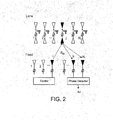
- An exemplary technique for accomplishing this is shown in FIG. 2 .
- An arbitrary feed element "i" radiates a coherent signal that impinges on lens element "j". A portion of the energy incident on lens element, will enter the lens phase shifter and (when the terminator load is switched to be reflective) will scatter energy toward the feed. Some of this backscattered signal will impinge on feed elements "k” and reference element "Ni", The phase difference of signals received at elements k and N i is measured.
- the bistatic measurements can be taken at multiple frequencies (to increase the number of measurements). In addition, measurements at two frequencies may be employed to resolve ambiguity between time and phase.
- phase unwrapping The process of resolving the range ambiguity is commonly known as "phase unwrapping.
- the unwrapping process for some situations can be complex (or perhaps not even possible), it is easily accomplished in an exemplary application of interest here since the feed elements are closely spaced . Specifically, since adjacent elements are typically less than half-a-wavelength apart, the phase difference will be less than one wavelength. Thus, in this case, there is no ambiguity between adjacent elements. Although there is a potential for ambiguity between widely spaced elements, this ambiguity may be resolved by "walking along" a path of the elements which lie between the subject elements. Unwrapping in this fashion is easily accomplished and is routinely done for many applications, including terrain mapping with interferometric synthetic aperture radar data.
- phase measure process may typically be encumbered by two factors as follows:
- FIG. 3 illustrates an exemplary technique for measuring a large number of pairs of elements simultaneously, without requiring a switching network.
- the technique employs the element phase shifters to inject an element-unique code which enables the processor to extract the desired phase for all pairs of elements simultaneously.
- the technique is as follows:
- a single element (i in FIG. 3 ) of the feed emits a signal of specified frequency. This signal impinges on each lens element, enters the lens element phase shifter, is reflected from the termination, returns through the phase shifter, and back toward the feed array where it impinges on each of the feed receive elements.
- the beam steering controller 100 directs the phase shifter associated with each receive feed element to change phase at an element-unique rate ⁇ i.
- the discrete value nearest the desired value is used.
- the outputs from each array element are combined and fed to the receiver (64B in this example) via the conventional receive network.
- the composite signal from the receiver is processed with an FFT 200 which generates a spectrum 202 with a series of peaks, each peak corresponding to one of the element-unique frequencies ⁇ i which were directed by the beam steering computer.
- phase of the signal received at each element is extracted from the FFT.
- the measured phases ⁇ j of the feed elements are then unwrapped at 210 to determine the desired bistatic ranges, from which the element locations and channel propagation parameters are determined.
- the discussion above tacitly assumes that the lens consists of a single element. Since the lenses of interest may have many elements, the returns from the multiple elements can conflict with the desired return from any single lens element. This can be avoided by switching the lens phase shifters at an element-unique rate (in addition to shifting the feed element phase shifters as discussed above.)
- FIGS. 4A-4B illustrate the concept.
- the beam steering controller directs the phase shifter associated with the "j th " lens element to change phase at an element-unique rate ⁇ j.
- the beam steering controller also directs the phase shifter associated with the "i th " feed element to change phase at an element-unique rate ⁇ i .
- the set of feed shifter rates W i and lens shifter rates ⁇ j can be chosen to avoid overlaps.
- FIG. 4B shows an example spectrum in which the lens phase shifter rates are separated by a rate which exceeds the highest shifting rate of any of the feed elements. As shown in FIG. 4B , all desired tones are separated in the receiver spectrum. Thus the desired bistatic ranges R ijk can be isolated and determined.
- the previously described exemplary embodiments employ passive elements which may be switched to a reflective terminator so as to reflect a phase-shifted signal.
- the concept can be extended to employ active devices which also amplify the signal. Such amplification may be of value to applications in which a strong return signal is desired.
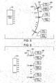
- FIG. 5 schematically illustrates an exemplary embodiment of a reflector 200 which is fed by an array feed 60.
- the reflector surface 210 can be populated by retro-reflector devices 220 which have a phase-shifter 222 and a switchable termination including a switch 224 selectively coupling the phase shifter to an absorptive load 226 or a reflective termination 228.
- the switchable termination provides two modes as follows:
- Reflective mode with the switch 224 connecting the reflective termination to the phase shifter 222, in which the incident energy from the feed 60 is passed through the phase shifter 222 and then directed back toward the feed 60,
- the bistatic path can be detected and uniquely identified in the receiver.
- the location of the phase center of the device can be determined using the processes described above. This phase center will be directly related to the reflector surface on which the device is mounted.
- FIG. 6 schematically depicts an exemplary embodiment of an ESA 300 and an arrangement of a plurality of retro-reflector devices 320, each connected to a phase shifter 322, in turn selectively connected by a switch 324 to an absorptive load or a reflective termination 328.
- the ESA can use the devices to determine the positions of its array elements and their associated channel propagation parameters, using the techniques described above with respect to FIGS. 1-4B .
- the locations of these reflectors does not need to be know (the locations are derived in the process).
- bistatic range measurements to determine the locations of the desired array elements has been described above. It should be noted that measurements of one-way range differences between an element and a reference element such as a coherent source or sources could as well be sufficient to locate the desired elements.
- the technique is capable of self-surveying the coherent sources and array elements when a sufficient number of coherent sources are within the antenna's field-of-view. Specifically, the redundancy in coherent sources enables their location to be determined along with the locations of the desired array elements.
- the relative locations are translated into a coordinate system common to the target. This can be accomplished by selecting some appropriate elements to serve as reference elements whose locations are know in a coordinate system common to the target. In the case of a three-dimensional scanning antenna, knowledge of the locations of three suitable elements is adequate to establish this relationship.
- the calibration process can be executed at high rate (to accommodate rapidly varying antenna parameters) and with little interruption to the normal operation of the antenna.
- Exemplary embodiments of the techniques described herein eliminate the dependence on precisely located coherent sources. This is accomplished by making a sufficient number of bistatic (or one-way) range measurements between various elements of the antenna such that the elements can be "self-located.”
- Exemplary features of the techniques may include one or more of the following:
- antennas May be applied to principal types of antennas, including conventional planar ESAs, array-fed lens antennas, array-fed reflector antennas, and conventional reflector antennas.
Landscapes
- Variable-Direction Aerials And Aerial Arrays (AREA)
- Aerials With Secondary Devices (AREA)
Applications Claiming Priority (1)
| Application Number | Priority Date | Filing Date | Title |
|---|---|---|---|
| US12/660,227 US8330662B2 (en) | 2010-02-23 | 2010-02-23 | Methods and apparatus for determining parameters of an array |
Publications (2)
| Publication Number | Publication Date |
|---|---|
| EP2362485A1 true EP2362485A1 (de) | 2011-08-31 |
| EP2362485B1 EP2362485B1 (de) | 2021-04-28 |
Family
ID=44021819
Family Applications (1)
| Application Number | Title | Priority Date | Filing Date |
|---|---|---|---|
| EP11155587.6A Active EP2362485B1 (de) | 2010-02-23 | 2011-02-23 | Verfahren und Vorrichtung zur Bestimmung der Parameter eines Arrays |
Country Status (2)
| Country | Link |
|---|---|
| US (2) | US8330662B2 (de) |
| EP (1) | EP2362485B1 (de) |
Cited By (1)
| Publication number | Priority date | Publication date | Assignee | Title |
|---|---|---|---|---|
| US20210088625A1 (en) * | 2019-09-24 | 2021-03-25 | International Business Machines Corporation | Multi-direction phased array calibration |
Families Citing this family (8)
| Publication number | Priority date | Publication date | Assignee | Title |
|---|---|---|---|---|
| US10062966B2 (en) * | 2011-04-12 | 2018-08-28 | Agence Spatiale Europeenne | Array antenna having a radiation pattern with a controlled envelope, and method of manufacturing it |
| FR2985121B1 (fr) * | 2011-12-22 | 2014-01-17 | Astrium Sas | Procede et systeme d'estimation d'une difference de marche d'un signal cible emis par un engin en orbite terrestre ou aerien |
| JP6271032B2 (ja) * | 2014-10-30 | 2018-01-31 | 三菱電機株式会社 | アンテナ諸元推定装置及びレーダ装置 |
| CN110537107B (zh) * | 2017-04-26 | 2023-11-07 | 三菱电机株式会社 | 移动距离计测装置 |
| JP7150641B2 (ja) * | 2019-03-12 | 2022-10-11 | 株式会社東芝 | アンテナシステム |
| US12196845B2 (en) * | 2020-03-31 | 2025-01-14 | Huawei Technologies Co., Ltd. | Systems and methods for locating user equipment in a wireless network |
| CN114915356B (zh) * | 2021-02-08 | 2024-08-16 | 周锡增 | 相位阵列天线校正方法 |
| CN114465675B (zh) * | 2022-04-12 | 2022-08-16 | 成都雷电微力科技股份有限公司 | 一种适用于拼阵的相控阵天线的校准方法 |
Citations (3)
| Publication number | Priority date | Publication date | Assignee | Title |
|---|---|---|---|---|
| JPS5443657A (en) * | 1977-09-13 | 1979-04-06 | Mitsubishi Electric Corp | Spherical sheel lens antenna |
| US20050001760A1 (en) * | 2003-07-02 | 2005-01-06 | Mrstik A. Vincent | Techniques for measurement of deformation of electronically scanned antenna array structures |
| WO2007039772A1 (en) * | 2005-10-06 | 2007-04-12 | Roke Manor Research Limited | Phase unwrapping algorithm for array calibration with signals of opportunity |
Family Cites Families (14)
| Publication number | Priority date | Publication date | Assignee | Title |
|---|---|---|---|---|
| FR1460030A (fr) * | 1965-10-14 | 1966-06-17 | Thomson Houston Comp Francaise | Perfectionnements aux antennes à balayage électronique |
| US5113193A (en) * | 1985-11-12 | 1992-05-12 | The United States Of America As Represented By The Secretary Of The Air Force | Autonomous synchronization of a bistatic synthetic aperture radar (SAR) system |
| DE3934155C2 (de) * | 1988-10-13 | 1999-10-07 | Mitsubishi Electric Corp | Verfahren zum Messen einer Amplitude und einer Phase jedes Antennenelementes einer phasengesteuerten Antennenanordnung sowie Antennenanordnung zum Durchführen des Verfahrens |
| US5140333A (en) * | 1991-08-23 | 1992-08-18 | Westinghouse Electric Corp. | System and method for operating transmit/receive modules of active aperture phased array antennas |
| US6025796A (en) * | 1996-12-09 | 2000-02-15 | Crosby, Ii; Robert G. | Radar detector for pre-impact airbag triggering |
| US6934511B1 (en) * | 1999-07-20 | 2005-08-23 | Andrew Corporation | Integrated repeater |
| US6351247B1 (en) * | 2000-02-24 | 2002-02-26 | The Boeing Company | Low cost polarization twist space-fed E-scan planar phased array antenna |
| WO2003067278A2 (en) * | 2002-02-08 | 2003-08-14 | Lockheed Martin Corporation | System and method for doppler track correlation for debris tracking |
| US7038618B2 (en) * | 2004-04-26 | 2006-05-02 | Budic Robert D | Method and apparatus for performing bistatic radar functions |
| US7440766B1 (en) * | 2004-06-07 | 2008-10-21 | University Of Hawaii | Method for employing multipath propagation in wireless radio communications |
| US7317428B2 (en) * | 2006-01-10 | 2008-01-08 | Lucent Technologies Inc. | Forming an antenna beam using an array of antennas to provide a wireless communication |
| US20090201206A1 (en) * | 2006-04-27 | 2009-08-13 | University Of Florida Research Foundation, Inc. | Method and system for flexible beampattern design using waveform diversity |
| EP2264484B1 (de) * | 2006-07-07 | 2017-06-21 | STMicroelectronics (Research & Development) Limited | Satellitenlokalisation |
| US7605767B2 (en) * | 2006-08-04 | 2009-10-20 | Raytheon Company | Space-fed array operable in a reflective mode and in a feed-through mode |
-
2010
- 2010-02-23 US US12/660,227 patent/US8330662B2/en active Active
-
2011
- 2011-02-23 EP EP11155587.6A patent/EP2362485B1/de active Active
-
2012
- 2012-11-05 US US13/669,331 patent/US8654016B2/en active Active
Patent Citations (4)
| Publication number | Priority date | Publication date | Assignee | Title |
|---|---|---|---|---|
| JPS5443657A (en) * | 1977-09-13 | 1979-04-06 | Mitsubishi Electric Corp | Spherical sheel lens antenna |
| US20050001760A1 (en) * | 2003-07-02 | 2005-01-06 | Mrstik A. Vincent | Techniques for measurement of deformation of electronically scanned antenna array structures |
| US6954173B2 (en) | 2003-07-02 | 2005-10-11 | Raytheon Company | Techniques for measurement of deformation of electronically scanned antenna array structures |
| WO2007039772A1 (en) * | 2005-10-06 | 2007-04-12 | Roke Manor Research Limited | Phase unwrapping algorithm for array calibration with signals of opportunity |
Cited By (2)
| Publication number | Priority date | Publication date | Assignee | Title |
|---|---|---|---|---|
| US20210088625A1 (en) * | 2019-09-24 | 2021-03-25 | International Business Machines Corporation | Multi-direction phased array calibration |
| US11789116B2 (en) * | 2019-09-24 | 2023-10-17 | International Business Machines Corporation | Multi-direction phased array calibration |
Also Published As
| Publication number | Publication date |
|---|---|
| EP2362485B1 (de) | 2021-04-28 |
| US8330662B2 (en) | 2012-12-11 |
| US8654016B2 (en) | 2014-02-18 |
| US20110205130A1 (en) | 2011-08-25 |
| US20130063315A1 (en) | 2013-03-14 |
Similar Documents
| Publication | Publication Date | Title |
|---|---|---|
| EP2362485B1 (de) | Verfahren und Vorrichtung zur Bestimmung der Parameter eines Arrays | |
| JP6853642B2 (ja) | レーダ装置 | |
| KR102124552B1 (ko) | 단벽 슬롯형 도파관 어레이들을 급전하기 위한 빔형성 네트워크 | |
| US9496611B2 (en) | System and method for coherent processing of signals of a plurality of phased arrays | |
| JP6883592B2 (ja) | 偏波フェーズドアレイレーダシステム及びその動作方法 | |
| US9070972B2 (en) | Wideband beam forming device; wideband beam steering device and corresponding methods | |
| EP3271968B1 (de) | Amplitudenvergleich-monopuls-radarsystem | |
| US8049661B1 (en) | Antenna array with robust failed-element processor | |
| US6954173B2 (en) | Techniques for measurement of deformation of electronically scanned antenna array structures | |
| US20240039173A1 (en) | Multiple input multiple steered output (mimso) radar | |
| US20240219552A1 (en) | Mimo radar using a frequency scanning antenna | |
| US6188481B1 (en) | Spatial interferometry | |
| JP3138728B2 (ja) | アレーアンテナの較正方法 | |
| WO2007040635A1 (en) | Improved thinned array antenna system | |
| JP2001099918A (ja) | ホログラフィックレーダ装置 | |
| JP6198547B2 (ja) | アンテナ装置 | |
| Cash et al. | Passive Phase Multiplication as a Means Towards Low-Cost, High-Performance Phased Array Antennas | |
| CN110383580B (zh) | 互质光学收发器阵列 | |
| CN110927696A (zh) | 用于接收光以探测对象的设备 | |
| Harter et al. | Realization of an innovative 3D imaging digital beamforming radar system | |
| HK1250092B (en) | An amplitude comparison monopulse radar system |
Legal Events
| Date | Code | Title | Description |
|---|---|---|---|
| PUAI | Public reference made under article 153(3) epc to a published international application that has entered the european phase |
Free format text: ORIGINAL CODE: 0009012 |
|
| 17P | Request for examination filed |
Effective date: 20110321 |
|
| AK | Designated contracting states |
Kind code of ref document: A1 Designated state(s): AL AT BE BG CH CY CZ DE DK EE ES FI FR GB GR HR HU IE IS IT LI LT LU LV MC MK MT NL NO PL PT RO RS SE SI SK SM TR |
|
| AX | Request for extension of the european patent |
Extension state: BA ME |
|
| STAA | Information on the status of an ep patent application or granted ep patent |
Free format text: STATUS: EXAMINATION IS IN PROGRESS |
|
| 17Q | First examination report despatched |
Effective date: 20180727 |
|
| RIC1 | Information provided on ipc code assigned before grant |
Ipc: G01S 7/40 20060101ALN20190719BHEP Ipc: H01Q 3/26 20060101ALI20190719BHEP Ipc: G01S 13/02 20060101ALN20190719BHEP Ipc: G01S 13/06 20060101AFI20190719BHEP Ipc: H01Q 21/00 20060101ALI20190719BHEP Ipc: H01Q 3/46 20060101ALI20190719BHEP Ipc: H01Q 15/02 20060101ALN20190719BHEP |
|
| REG | Reference to a national code |
Ref country code: DE Ref legal event code: R079 Ref document number: 602011070803 Country of ref document: DE Free format text: PREVIOUS MAIN CLASS: H01Q0003260000 Ipc: G01S0013060000 |
|
| RIC1 | Information provided on ipc code assigned before grant |
Ipc: H01Q 3/26 20060101ALI20201019BHEP Ipc: G01S 7/40 20060101ALN20201019BHEP Ipc: H01Q 3/46 20060101ALI20201019BHEP Ipc: H01Q 21/00 20060101ALI20201019BHEP Ipc: H01Q 15/02 20060101ALN20201019BHEP Ipc: G01S 13/02 20060101ALN20201019BHEP Ipc: G01S 13/06 20060101AFI20201019BHEP |
|
| GRAP | Despatch of communication of intention to grant a patent |
Free format text: ORIGINAL CODE: EPIDOSNIGR1 |
|
| STAA | Information on the status of an ep patent application or granted ep patent |
Free format text: STATUS: GRANT OF PATENT IS INTENDED |
|
| RIC1 | Information provided on ipc code assigned before grant |
Ipc: G01S 7/40 20060101ALN20201030BHEP Ipc: H01Q 21/00 20060101ALI20201030BHEP Ipc: H01Q 3/46 20060101ALI20201030BHEP Ipc: H01Q 15/02 20060101ALN20201030BHEP Ipc: G01S 13/02 20060101ALN20201030BHEP Ipc: G01S 13/06 20060101AFI20201030BHEP Ipc: H01Q 3/26 20060101ALI20201030BHEP |
|
| INTG | Intention to grant announced |
Effective date: 20201209 |
|
| GRAS | Grant fee paid |
Free format text: ORIGINAL CODE: EPIDOSNIGR3 |
|
| GRAA | (expected) grant |
Free format text: ORIGINAL CODE: 0009210 |
|
| STAA | Information on the status of an ep patent application or granted ep patent |
Free format text: STATUS: THE PATENT HAS BEEN GRANTED |
|
| AK | Designated contracting states |
Kind code of ref document: B1 Designated state(s): AL AT BE BG CH CY CZ DE DK EE ES FI FR GB GR HR HU IE IS IT LI LT LU LV MC MK MT NL NO PL PT RO RS SE SI SK SM TR |
|
| REG | Reference to a national code |
Ref country code: GB Ref legal event code: FG4D |
|
| REG | Reference to a national code |
Ref country code: CH Ref legal event code: EP |
|
| REG | Reference to a national code |
Ref country code: DE Ref legal event code: R096 Ref document number: 602011070803 Country of ref document: DE |
|
| REG | Reference to a national code |
Ref country code: IE Ref legal event code: FG4D |
|
| REG | Reference to a national code |
Ref country code: LT Ref legal event code: MG9D |
|
| PG25 | Lapsed in a contracting state [announced via postgrant information from national office to epo] |
Ref country code: BG Free format text: LAPSE BECAUSE OF FAILURE TO SUBMIT A TRANSLATION OF THE DESCRIPTION OR TO PAY THE FEE WITHIN THE PRESCRIBED TIME-LIMIT Effective date: 20210728 Ref country code: HR Free format text: LAPSE BECAUSE OF FAILURE TO SUBMIT A TRANSLATION OF THE DESCRIPTION OR TO PAY THE FEE WITHIN THE PRESCRIBED TIME-LIMIT Effective date: 20210428 Ref country code: NL Free format text: LAPSE BECAUSE OF FAILURE TO SUBMIT A TRANSLATION OF THE DESCRIPTION OR TO PAY THE FEE WITHIN THE PRESCRIBED TIME-LIMIT Effective date: 20210428 Ref country code: LT Free format text: LAPSE BECAUSE OF FAILURE TO SUBMIT A TRANSLATION OF THE DESCRIPTION OR TO PAY THE FEE WITHIN THE PRESCRIBED TIME-LIMIT Effective date: 20210428 Ref country code: FI Free format text: LAPSE BECAUSE OF FAILURE TO SUBMIT A TRANSLATION OF THE DESCRIPTION OR TO PAY THE FEE WITHIN THE PRESCRIBED TIME-LIMIT Effective date: 20210428 |
|
| PG25 | Lapsed in a contracting state [announced via postgrant information from national office to epo] |
Ref country code: RS Free format text: LAPSE BECAUSE OF FAILURE TO SUBMIT A TRANSLATION OF THE DESCRIPTION OR TO PAY THE FEE WITHIN THE PRESCRIBED TIME-LIMIT Effective date: 20210428 Ref country code: SE Free format text: LAPSE BECAUSE OF FAILURE TO SUBMIT A TRANSLATION OF THE DESCRIPTION OR TO PAY THE FEE WITHIN THE PRESCRIBED TIME-LIMIT Effective date: 20210428 Ref country code: LV Free format text: LAPSE BECAUSE OF FAILURE TO SUBMIT A TRANSLATION OF THE DESCRIPTION OR TO PAY THE FEE WITHIN THE PRESCRIBED TIME-LIMIT Effective date: 20210428 Ref country code: GR Free format text: LAPSE BECAUSE OF FAILURE TO SUBMIT A TRANSLATION OF THE DESCRIPTION OR TO PAY THE FEE WITHIN THE PRESCRIBED TIME-LIMIT Effective date: 20210729 Ref country code: IS Free format text: LAPSE BECAUSE OF FAILURE TO SUBMIT A TRANSLATION OF THE DESCRIPTION OR TO PAY THE FEE WITHIN THE PRESCRIBED TIME-LIMIT Effective date: 20210828 Ref country code: PL Free format text: LAPSE BECAUSE OF FAILURE TO SUBMIT A TRANSLATION OF THE DESCRIPTION OR TO PAY THE FEE WITHIN THE PRESCRIBED TIME-LIMIT Effective date: 20210428 Ref country code: NO Free format text: LAPSE BECAUSE OF FAILURE TO SUBMIT A TRANSLATION OF THE DESCRIPTION OR TO PAY THE FEE WITHIN THE PRESCRIBED TIME-LIMIT Effective date: 20210728 Ref country code: PT Free format text: LAPSE BECAUSE OF FAILURE TO SUBMIT A TRANSLATION OF THE DESCRIPTION OR TO PAY THE FEE WITHIN THE PRESCRIBED TIME-LIMIT Effective date: 20210830 Ref country code: ES Free format text: LAPSE BECAUSE OF FAILURE TO SUBMIT A TRANSLATION OF THE DESCRIPTION OR TO PAY THE FEE WITHIN THE PRESCRIBED TIME-LIMIT Effective date: 20210428 |
|
| REG | Reference to a national code |
Ref country code: NL Ref legal event code: MP Effective date: 20210428 |
|
| PG25 | Lapsed in a contracting state [announced via postgrant information from national office to epo] |
Ref country code: RO Free format text: LAPSE BECAUSE OF FAILURE TO SUBMIT A TRANSLATION OF THE DESCRIPTION OR TO PAY THE FEE WITHIN THE PRESCRIBED TIME-LIMIT Effective date: 20210428 Ref country code: DK Free format text: LAPSE BECAUSE OF FAILURE TO SUBMIT A TRANSLATION OF THE DESCRIPTION OR TO PAY THE FEE WITHIN THE PRESCRIBED TIME-LIMIT Effective date: 20210428 Ref country code: CZ Free format text: LAPSE BECAUSE OF FAILURE TO SUBMIT A TRANSLATION OF THE DESCRIPTION OR TO PAY THE FEE WITHIN THE PRESCRIBED TIME-LIMIT Effective date: 20210428 Ref country code: EE Free format text: LAPSE BECAUSE OF FAILURE TO SUBMIT A TRANSLATION OF THE DESCRIPTION OR TO PAY THE FEE WITHIN THE PRESCRIBED TIME-LIMIT Effective date: 20210428 Ref country code: SK Free format text: LAPSE BECAUSE OF FAILURE TO SUBMIT A TRANSLATION OF THE DESCRIPTION OR TO PAY THE FEE WITHIN THE PRESCRIBED TIME-LIMIT Effective date: 20210428 Ref country code: SM Free format text: LAPSE BECAUSE OF FAILURE TO SUBMIT A TRANSLATION OF THE DESCRIPTION OR TO PAY THE FEE WITHIN THE PRESCRIBED TIME-LIMIT Effective date: 20210428 |
|
| REG | Reference to a national code |
Ref country code: DE Ref legal event code: R097 Ref document number: 602011070803 Country of ref document: DE |
|
| PLBE | No opposition filed within time limit |
Free format text: ORIGINAL CODE: 0009261 |
|
| STAA | Information on the status of an ep patent application or granted ep patent |
Free format text: STATUS: NO OPPOSITION FILED WITHIN TIME LIMIT |
|
| 26N | No opposition filed |
Effective date: 20220131 |
|
| PG25 | Lapsed in a contracting state [announced via postgrant information from national office to epo] |
Ref country code: IS Free format text: LAPSE BECAUSE OF FAILURE TO SUBMIT A TRANSLATION OF THE DESCRIPTION OR TO PAY THE FEE WITHIN THE PRESCRIBED TIME-LIMIT Effective date: 20210828 Ref country code: AL Free format text: LAPSE BECAUSE OF FAILURE TO SUBMIT A TRANSLATION OF THE DESCRIPTION OR TO PAY THE FEE WITHIN THE PRESCRIBED TIME-LIMIT Effective date: 20210428 |
|
| PG25 | Lapsed in a contracting state [announced via postgrant information from national office to epo] |
Ref country code: IT Free format text: LAPSE BECAUSE OF FAILURE TO SUBMIT A TRANSLATION OF THE DESCRIPTION OR TO PAY THE FEE WITHIN THE PRESCRIBED TIME-LIMIT Effective date: 20210428 |
|
| PG25 | Lapsed in a contracting state [announced via postgrant information from national office to epo] |
Ref country code: MC Free format text: LAPSE BECAUSE OF FAILURE TO SUBMIT A TRANSLATION OF THE DESCRIPTION OR TO PAY THE FEE WITHIN THE PRESCRIBED TIME-LIMIT Effective date: 20210428 |
|
| REG | Reference to a national code |
Ref country code: CH Ref legal event code: PL |
|
| REG | Reference to a national code |
Ref country code: BE Ref legal event code: MM Effective date: 20220228 |
|
| PG25 | Lapsed in a contracting state [announced via postgrant information from national office to epo] |
Ref country code: LU Free format text: LAPSE BECAUSE OF NON-PAYMENT OF DUE FEES Effective date: 20220223 |
|
| PG25 | Lapsed in a contracting state [announced via postgrant information from national office to epo] |
Ref country code: LI Free format text: LAPSE BECAUSE OF NON-PAYMENT OF DUE FEES Effective date: 20220228 Ref country code: IE Free format text: LAPSE BECAUSE OF NON-PAYMENT OF DUE FEES Effective date: 20220223 Ref country code: CH Free format text: LAPSE BECAUSE OF NON-PAYMENT OF DUE FEES Effective date: 20220228 |
|
| PG25 | Lapsed in a contracting state [announced via postgrant information from national office to epo] |
Ref country code: BE Free format text: LAPSE BECAUSE OF NON-PAYMENT OF DUE FEES Effective date: 20220228 |
|
| P01 | Opt-out of the competence of the unified patent court (upc) registered |
Effective date: 20230530 |
|
| PG25 | Lapsed in a contracting state [announced via postgrant information from national office to epo] |
Ref country code: HU Free format text: LAPSE BECAUSE OF FAILURE TO SUBMIT A TRANSLATION OF THE DESCRIPTION OR TO PAY THE FEE WITHIN THE PRESCRIBED TIME-LIMIT; INVALID AB INITIO Effective date: 20110223 |
|
| PG25 | Lapsed in a contracting state [announced via postgrant information from national office to epo] |
Ref country code: MK Free format text: LAPSE BECAUSE OF FAILURE TO SUBMIT A TRANSLATION OF THE DESCRIPTION OR TO PAY THE FEE WITHIN THE PRESCRIBED TIME-LIMIT Effective date: 20210428 Ref country code: CY Free format text: LAPSE BECAUSE OF FAILURE TO SUBMIT A TRANSLATION OF THE DESCRIPTION OR TO PAY THE FEE WITHIN THE PRESCRIBED TIME-LIMIT Effective date: 20210428 |
|
| PG25 | Lapsed in a contracting state [announced via postgrant information from national office to epo] |
Ref country code: TR Free format text: LAPSE BECAUSE OF FAILURE TO SUBMIT A TRANSLATION OF THE DESCRIPTION OR TO PAY THE FEE WITHIN THE PRESCRIBED TIME-LIMIT Effective date: 20210428 |
|
| PG25 | Lapsed in a contracting state [announced via postgrant information from national office to epo] |
Ref country code: MT Free format text: LAPSE BECAUSE OF FAILURE TO SUBMIT A TRANSLATION OF THE DESCRIPTION OR TO PAY THE FEE WITHIN THE PRESCRIBED TIME-LIMIT Effective date: 20210428 |
|
| REG | Reference to a national code |
Ref country code: AT Ref legal event code: MK05 Ref document number: 1831756 Country of ref document: AT Kind code of ref document: T Effective date: 20210428 |
|
| PG25 | Lapsed in a contracting state [announced via postgrant information from national office to epo] |
Ref country code: AT Free format text: LAPSE BECAUSE OF FAILURE TO SUBMIT A TRANSLATION OF THE DESCRIPTION OR TO PAY THE FEE WITHIN THE PRESCRIBED TIME-LIMIT Effective date: 20210428 |
|
| PGFP | Annual fee paid to national office [announced via postgrant information from national office to epo] |
Ref country code: GB Payment date: 20260121 Year of fee payment: 16 |
|
| PGFP | Annual fee paid to national office [announced via postgrant information from national office to epo] |
Ref country code: DE Payment date: 20260121 Year of fee payment: 16 |
|
| PGFP | Annual fee paid to national office [announced via postgrant information from national office to epo] |
Ref country code: FR Payment date: 20260121 Year of fee payment: 16 |