EP2362515B1 - Steuerungsverfahren für netzgekoppelten Einzelphasen-LCL-Umrichter - Google Patents
Steuerungsverfahren für netzgekoppelten Einzelphasen-LCL-Umrichter Download PDFInfo
- Publication number
- EP2362515B1 EP2362515B1 EP10154113A EP10154113A EP2362515B1 EP 2362515 B1 EP2362515 B1 EP 2362515B1 EP 10154113 A EP10154113 A EP 10154113A EP 10154113 A EP10154113 A EP 10154113A EP 2362515 B1 EP2362515 B1 EP 2362515B1
- Authority
- EP
- European Patent Office
- Prior art keywords
- grid
- side current
- voltage
- inverter
- term
- Prior art date
- Legal status (The legal status is an assumption and is not a legal conclusion. Google has not performed a legal analysis and makes no representation as to the accuracy of the status listed.)
- Not-in-force
Links
Images






Classifications
-
- H—ELECTRICITY
- H02—GENERATION; CONVERSION OR DISTRIBUTION OF ELECTRIC POWER
- H02J—ELECTRIC POWER NETWORKS; CIRCUIT ARRANGEMENTS OR SYSTEMS FOR SUPPLYING OR DISTRIBUTING ELECTRIC POWER; SYSTEMS FOR STORING ELECTRIC ENERGY
- H02J3/00—Circuit arrangements for AC mains or AC distribution networks
- H02J3/01—Arrangements for reducing harmonics or ripples
-
- Y—GENERAL TAGGING OF NEW TECHNOLOGICAL DEVELOPMENTS; GENERAL TAGGING OF CROSS-SECTIONAL TECHNOLOGIES SPANNING OVER SEVERAL SECTIONS OF THE IPC; TECHNICAL SUBJECTS COVERED BY FORMER USPC CROSS-REFERENCE ART COLLECTIONS [XRACs] AND DIGESTS
- Y02—TECHNOLOGIES OR APPLICATIONS FOR MITIGATION OR ADAPTATION AGAINST CLIMATE CHANGE
- Y02E—REDUCTION OF GREENHOUSE GAS [GHG] EMISSIONS, RELATED TO ENERGY GENERATION, TRANSMISSION OR DISTRIBUTION
- Y02E40/00—Technologies for an efficient electrical power generation, transmission or distribution
- Y02E40/40—Arrangements for reducing harmonics
Definitions
- the present invention relates to controlling grid-connected converters and more particularly to an arrangement where an LCL filter is used as the interface between a voltage source inverter (VSI) and grid.
- VSI voltage source inverter
- the applicability of these systems includes static VAR compensators, uninterruptible power systems, power flow compensators, and distributed generation system interfaces (photovoltaic, wind power, micro turbine, fuel cell, etc.), along others.
- distributed generation applications the primary energy source is connected to the grid by means of a power converter, usually a voltage source inverter (VSI), and a filter.
- VSI voltage source inverter
- L filter-based converters are becoming more popular due to their improved characteristics that allow them to comply with the every day more restrictive standards.
- L filter-based converters present more complex dynamics than L filter-based converters.
- a resonance arises, which compromises the stability of the system and makes the system more susceptible to grid disturbances.
- control schemes must be able to alleviate the harmonics distortion which has become an almost mandatory feature for the controller design.
- implementation of such controllers should be kept as simple as possible and without the requirement of additional sensors to keep the implementation cost comparable to conventional L filter-based converters.
- the authors propose to use similar controllers for the LCL filter as in the L filter inverter. They consider that at low frequencies the response between a single L filter and an LCL filter is similar. In fact, the authors use PI controllers for both the current and the DC link voltage controllers. Moreover, they propose to add a passive resistor in parallel with the outer inductor to somehow improve stability at the cost of dissipation losses.
- the inverter is controlled to emulate a resistor so that the current will be a scaled version of the grid voltage. However, if the grid voltage is distorted, then the current will also be distorted.
- the voltage outer loop is used to produce the current reference, and thus its bandwidth is made very small to avoid further distortion reinjection.
- the authors propose a controller that requires that only the current on the inverter side and the grid voltage are measured.
- the scheme is based on a P+R controller for the stability and tracking of the fundamental, and includes a bank of harmonic oscillators for the compensation of harmonic distortion (HC).
- HC harmonic distortion
- the proposed scheme controls the inverter-side current rather than the grid current, and thus it may experience some inaccuracies on the delivered output current.
- the authors also propose to include the delay due to sampling, which apparently improves stability.
- they use basically the same controller, except that this time they measure the current on the grid side.
- direct application of this controller to the grid current may entail stability issues as there is missing damping that cannot be injected with a simple P+R controller.
- the authors propose a controller which is a cascade interconnection of PI and deadbeat controllers.
- the Pi is used as an outer loop to control the grid current, delivering the reference for the inverter-side current, which is then stabilized by the deadbeat controller.
- the controller requires the measurements of all variables in the LCL filter, and thus their feedback on the controller represents the stabilization mechanism.
- the effect of the harmonic distortion in the grid voltage is studied, but no harmonic mechanism is included to overcome this issue, this compensation is left to the frequency characteristics of the cascade controller.
- the authors propose modifications to the conventional DPC control to consider the LCL filter. They propose to alleviate the resonance issue by injecting active damping. For this purpose the capacitor current is measured in addition to the converter-side current. A harmonic compensation scheme is also presented, which is based on the synchronous reference frame representations of signals.
- An object of the present invention is .thus to provide a method so as to solve the above problems.
- the objects of the invention are achieved by a method which is characterized by what is stated in the independent claims.
- the preferred embodiments of the invention are disclosed in the dependent claims.
- the invention is based on the idea of introducing an active damping injection (ADI) and a harmonics compensation mechanism (HCM) to a control method for controlling the current of a single-phase inverter connected to the grid through an LCL filter.
- the active damping injection (ADI) damps the resonance of the LCL filter and the harmonic compensation mechanism (HCM) copes with harmonic distortion present in the grid voltage.
- the control method design is based on the model structure, and thus the information of the dynamical structure is incorporated in the method to allow better dynamical performances.
- the method also comprises a feedback control loop to inject the required active damping (ADI). As not all required quantities are measured, an observer is used to form estimates of the non-measured signals.
- a reducer order observer may also be included to reconstruct the non-available states.
- the R-OBS uses information on the measured inverter-side current, grid voltage, and injected voltage signal produced by the inverter.
- the use of observed variables in the place of non-available states for control implementation is well supported by the separation principle.
- the harmonic compensation mechanism is formed by a set of quadratic signals generators (QSGs) where the fundamental frequency enters as an input variable.
- An advantage of the method of the present invention is that the method controls the grid-side current directly, which makes the system response less sensitive to disturbances on the grid side, and guarantees a cleaner response of the grid-side current. Another advantage of the method is that no additional sensors are required, thus maintaining an easy implementation without extra costs. Yet another advantage is that the method functions properly in cases of variation of the fundamental frequency since the harmonic compensation mechanism (HCM) uses the fundamental frequency as an input variable. The value of the fundamental frequency can be generated by an external scheme such as a PLL scheme.
- the present invention concentrates on the current control of a grid-connected LCL inverter. That is, the control method according to the present invention generates an expression for the injected voltage e , which can then be reproduced by a suitable voltage source inverter (VSI) connected to a DC voltage source and based on an appropriate modulation algorithm.
- VSI voltage source inverter
- the latter includes alternative energy sources with or without an additional converter or passive energy storage elements which are able to provide a constant DC voltage to the voltage source inverter (VSI). Therefore, signal e is considered thorough this document as the control input signal.
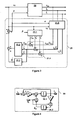
- Figure 1 is illustrates a single-phase inverter 1 connected to a grid 2 through an LCL filter 3.
- the inverter 1 has a DC voltage source 4 as an energy source.
- the mathematical model of the grid-connected LCL inverter 1 + 3 is where i i is the current of inductor L i , also referred to as the inverter-side current or the converter-side current; i 0 is the current of inductor L 0 , also referred as the grid-side current; v C 0 is the voltage in the capacitor C 0 ; and v s is the grid voltage.
- FIG. 2 A block diagram representation of this system is shown in Figure 2 . It represents a linear time-invariant (LTI) third order system 10 having as control input the signal e , and as output the signal i 1 .
- the grid voltage v S acts as an external disturbance.
- the injected voltage e and the grid voltage v S transfer functions are represented by terms 10.1 and 10.2, respectively, in Figure 2 .
- the scaling factor 1 / v S , RMS 2 is included to avoid numerical errors only and thus an exact value is not required; scalar P represents the modulation amplitude of the current reference i 0 * . In fact, P gives an approximate of the delivered power, and is computed by a suitable outer control loop.
- the outer loop In case of alternative energy sources, the outer loop generates P to guarantee operation on the maximum power point (MPP).
- MPP maximum power point
- the design of the outer loop is out of the scope of the present invention, and thus P is assumed available. It is also assumed that the dynamics on this outer loop are considerably slower than the dynamics of the LCL filter and thus, on the basis of a scale separation principle, the scalar P can be viewed as a constant in the dynamics of the LCL filter.
- FIG. 3 A block diagram of the control method according to the present invention is shown in Figure 3 .
- the LCL filter 20 is connected to a control system 21 comprising the control method according to the present invention.
- the control method in control system 21 in figure 12 comprises a reference generation phase 21.1.
- a grid-side current reference i 0 * , a inverter-side current reference i 1 * and a capacitor voltage reference v C ⁇ 0 * are formed in the reference generation phase 21.1.
- the grid-side current reference i 0 * defined in (1) requires knowledge of the fundamental component v S ,1 , which is not available. Different methods can be used to extract or estimate the fundamental component of the grid voltage v S , and perhaps an estimate of the fundamental frequency. The last is especially useful in the case that the fundamental frequency is not known or varies slowly with time. These are in fact the functions of any phase-locked loop (PLL) scheme, and thus any PLL scheme can be used for this purpose.
- PLL phase-locked loop
- a very basic PLL scheme for the estimation of the fundamental component of the grid voltage v S can be used. It assumes that the fundamental frequency ⁇ 0 is available.
- This estimator is referred to as the fundamental quadrature signals generator (F-QSG), as it generates estimates for the fundamental component v S ,1 of the grid voltage and its quadrature companion signal ⁇ S, 1 .
- Figure 4 illustrates a block diagram embodying the fundamental quadrature signals generator (F-QSG).
- the F-QSG 30 in Figure 4 comprises two integrators 30.1 and 30.2.
- the first integrator 30.1 produces the fundamental component v S ,1 of the grid voltage and the second integrator 30.2 produces the quadrature companion signal ⁇ S, 1 .
- the opposite value of the first integrator 30.1 output multiplied by the fundamental frequency ⁇ 0 is used as the input for the second integrator 30.2.
- the input for the first integrator 30.1 is produced by determining the difference ⁇ S between the grid voltage v S and the output of the first integrator 30.1, multiplying the difference ⁇ S with the estimation gain ⁇ 1 and adding the product of the output of the second integrator 30.2 and the fundamental frequency ⁇ 0 to the product of the difference ⁇ S with the estimation gain ⁇ 1 .
- the main interest of the controller is to guarantee tracking of the grid-side current i 0 towards its reference i 0 * only. That is, the tracking of the other variables towards their corresponding references is not crucial, as long as they remain bounded, and thus the controller can be further simplified by approximating the references for i 1 * and v C ⁇ 0 * as follows v C ⁇ 0 * ⁇ v ⁇ S , 1 i 1 * ⁇ i 0 * + ⁇ 0 ⁇ C 0 ⁇ ⁇ ⁇ S , 1 and by relaying in the harmonic compensation capability of a harmonics compensation mechanism (HCM), which must be able to absorb the terms that have been neglected from the references (6) above.
- HCM harmonics compensation mechanism
- the harmonics compensation mechanism (HCM) is discussed in more detail later on in this document.
- the term ⁇ 0 C 0 ⁇ S ,1 is preserved for i 1 * as this term has a considerable value incorporating the necessary phase shift to i 1 , which may have a positive effect during transients.
- the active damping injection part 21.2 in Figure 3 comprises means for forming an injection term for damping the resonance of the LCL filter by using an active damping injection mechanism (ADI).
- ADI active damping injection mechanism
- the separation principle [11] is used for this part of the controller design. It allows to independently design the controller in two parts: a full state feedback part, which is based on the assumption that all the state variables are available; and an observer part, to estimate the non-available states. Then, in the controller implementation, the unavailable variables are replaced by their estimates. The observer design is discussed later on this document.
- a controller is designed to guarantee tracking on this variable.
- Figure 5 illustrates a block diagram of the LCL system 40 having as output the grid-side current i 0 and the injected voltage e as control input.
- the grid voltage v S enters as an external disturbance.
- the injected voltage e and the grid voltage v S transfer functions are represented by terms 40.1 and 40.2, respectively.
- i 0 ⁇ i 0 - i 0 *
- i 0 * P ⁇ v ⁇ S , 1 / v S , RMS 2 as defined before
- a 0 , a 1 and a 2 are positive design parameters used to introduce the required damping to guarantee stability.
- This procedure is known in the literature of power electronics as active damping injection, as the damping is injected without the need of passive elements. It can be shown that this controller guarantees exponential stability provided that L 1 + L 0 L 0 ⁇ C 0 ⁇ L 1 + a 1 > a 0 a 2 , a 2 > 0 ; a 0 > 0.
- ⁇ - L 1 + L 0 ⁇ P v S , RMS 2 ⁇ v ⁇ ⁇ S , 1 - C 0 ⁇ L 1 ⁇ v ⁇ S - L 0 ⁇ C 0 ⁇ L 1 ⁇ P v S , RMS 2 ⁇ v ⁇ ... S , 1
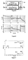
- Figure 6 shows the frequency responses of the original undamped system represented by curves 50.1 and 50.2 and of the closed loop system represented by curves 51.1 and 51.2.
- the natural resonant peak of the LCL filter is considerably damped.
- the poles 60.1 and 60.2 in the imaginary axis, as well as the pole 60.3 in the origin have all been shifted to the left to locations 61.1, 61.2 and 61.3.
- the poles 61.1, 61.2 and 61.3 of the closed loop system are considered shifted to the left in such a way that the poles 61.1 and 61.2, originally on the imaginary axis, are now located at 0.1 ⁇ res ⁇ j 1.05 ⁇ res , and the pole 61.3, originally at the origin, is now located at 0.4 ⁇ res , using the natural resonance frequency ⁇ res of the original system.
- the real parts of the complex poles are placed at 1/10 of the resonance frequency, and the real pole is moved four times farther than the real part of the complex poles. This allows the introduction of small damping while preserving stability even for considerable variations in the system parameters.
- the control method in the control system 21 in Figure 3 also comprises means 21.3 for compensating the harmonic distortion.
- ⁇ k is a positive design parameter representing the estimation gain for the k th harmonic component ⁇ k
- k ⁇ ⁇ 1,3,5,... ⁇ represents the indexes of the harmonics under concern.
- the set of harmonic indexes usually includes the fundamental to guarantee tracking and the higher order harmonics of the grid voltage v S , for instance the odd harmonics for harmonic cancellation.
- FIG 8 illustrates a block diagram representation of the closed loop system 70 with the harmonic compensator mechanism (HCM) 71.
- the frequency response of the controlled system is given in Figure 9 , where it can be observed that the effect of the harmonic compensator mechanism (HCM) is the introduction of notches at the harmonics under concern.
- the solid curves 80.1 and 81.1 represent the closed loop system with the harmonic compensator mechanism (HCM) and the dashed curves 80.2 and 81.2 represent the original undamped system.
- the estimation of ⁇ 0 can be performed using a PLL scheme.
- An embodiment of the harmonic compensator mechanism (HCM) based on this concept is shown in Figure 10 .
- the harmonic compensator mechanism (HCM) 90 in Figure 10 is a bank of quadrature signals generators (QSG) 90.1 - 90. k tuned at the harmonics under concern. Each QSG is referred to as the k th harmonic quadratic signals generator ( k th-QSG).
- the QSG may be implemented in a similar manner as the fundamental quadrature signals generator (F-QSG).
- the fundamental frequency ⁇ 0 is multiplied by the k value of the harmonic component under concern.
- a first tuning rule for the estimation gains ⁇ k can be stated as follows.
- the response of the remaining dynamics observed by the harmonic compensator mechanism (HCM) is basically a first order system with a pole located at a higher frequency.
- R-OBS reduced order observer
- the conventional observer design method [11] or the Immersion and Invariance method (I&I) proposed in [12] can be used in the observer design. Either method yields quite similar results.
- the Immersion and Invariance method (I&I) is preferred as the procedure seems simpler and in some cases yields simpler expressions.
- ⁇ 1 and ⁇ 2 are observer states and ⁇ 1 and ⁇ 2 are two design parameters.
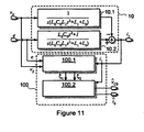
- FIG. 11 illustrates a block diagram of the connection of the R-OBS 100 with the plant 10 which is the same as in Figure 2 .
- the R-OBS 100 is divided into two parts: the observer dynamics 100.1 and the signal reconstruction 100.2.
- the observer implementation requires the measured signals v S and i 1 , the control signal e , and the system parameters L 0 , C 0 and L 1 .
- the three parameters now appear combined in the form of only two ratios L 1 / L 0 and L 1 l C 0 . This may report some advantages regarding the robustness with respect to parameter uncertainties.
- the other parameters appear as a single quotient C 0 / L 0 which may represent an advantage regarding the robustness against parameter uncertainties.
- Figure 12 illustrates a block diagram of a preferred embodiment of the control method according to the present invention.
- the LCL filter 10 is represented by a sum of transfer functions, where the first term 10.1 represents the transfer function for the grid voltage v S and the second term 10.2 represents the transfer function for the inverter produced voltage e .
- the subtraction of the terms 10.1 and 10.2 produces the inverter-side current i 1 , which is measured and used in the control method.
- the reference generation in the control method 110 is done by using a fundamental quadrature signals generator (F-QSG) 110.1 to produce the fundamental component v S ,1 of the grid voltage and its quadrature companion signal ⁇ S, 1 .
- the fundamental quadrature signals generator (F-QSG) 110.1 is realized using equations (3).
- the control method comprises means 110.2 to 110.5 to produce the references i 0 * , i 1 * and v C ⁇ 0 * from the fundamental component v S, 1 of the grid voltage v S and its quadrature companion signal ⁇ S,1 according equations (4, 6).
- the harmonic compensation 110.6 is done by using a harmonics compensation mechanism (HCM) described in equation (13).
- the harmonic compensation mechanism (HCM) realization is done by using equations (14).
- the non-available signals v C 0 and i 0 are replaced by their estimates v ⁇ C 0 and î 0 , respectively, using a reduced order observer 110.7, which is realized according equations (17 to 18).
- the replacement of the signals with their estimates is well supported by the separation principle stated above.
- the means for implementing the method may for instance be a processor, a DSP, or a programmable logic device (PLD), for example an FPGA.
- PLD programmable logic device
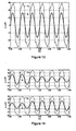
- Figure 13 shows that, in the steady state, the grid-side current i 0 tracks a pure sinusoidal signal in phase with the grid voltage v S , despite the high distortion on the grid voltage.
- Figure 14 shows that the shape of the grid-side current i 0 remains sinusoidal, after an almost negligible transient, during step changes in the grid irradiation from 1000 W/m 2 to 500 W/m 2 (top part of Figure 14 ) and back (bottom part of Figure 14 ).
- Figure 15 shows the estimate of the fundamental component v ⁇ S ,1 of the grid voltage.
- the estimate is built in the F-QSG. It is shown that, after a relatively short transient during start up (top part of Figure 15 ), the estimate v ⁇ S ,1 reaches the shape of a pure sinusoidal signal. In fact, it can be observed that this estimate equals the real fundamental component v S ,1 after the transient (bottom part of Figure 15 ). All these take place in spite of the highly distorted grid voltage v S .
- Figure 16 shows the transient of (top part of Figure 16 ) the grid-side current i 0 and grid-side current estimate î 0 , and (bottom part of Figure 16 ) capacitor voltage v C 0 and capacitor voltage estimate v ⁇ C 0 at the start up.
- An initial condition different to zero was introduced intentionally in the observed states to see this transient. It is shown that the states are perfectly reconstructed after an almost imperceptible transient.
- Figure 17 shows that the error between the real grid current i 0 and its reference i 0 * reaches zero after a relatively short transient.
- FIG. 19 illustrates transients of the grid-side current observation error ( i 0 - î 0 ) during step changes in irradiation from 1000 W/m 2 to 500 W/m 2 (top part of Figure 19 ) and back (bottom part of Figure 19 ).
- the difference between the real and the estimated grid-side currents, i.e., i 0 - î 0 is no longer zero, but there is a ripple at the fundamental frequency. This means that the parameter mismatch causes a slight phase shift with respect to the real value.
Landscapes
- Engineering & Computer Science (AREA)
- Power Engineering (AREA)
- Supply And Distribution Of Alternating Current (AREA)
- Inverter Devices (AREA)
- Dc-Dc Converters (AREA)
Claims (17)
- Ein Verfahren zur Steuerung der netzseitigen Spannung eines einphasigen netzgekoppelten Spannungsquellenumrichters mit einem LCL-Filter, der zwischen dem Output des Umrichters und dem Netz angeschlossen ist, wobei das Verfahren die Schritte aufweist, eine Netzspannung (ν S ) und mindestens ein Signal in einer Gruppe von Signalen, die einen netzseitigen Strom (i 0), einem umrichterseitigen Strom (i 1) und eine Kondensatorspannung (v C0) aufweisen, zu messen, dadurch gekennzeichnet, dass das Verfahren folgende Schritte aufweist:die fundamentale Komponente (vS ,1) der Netzspannung (vS ) schätzen,eine netzseitige Stromreferenz


 Schätzungen für die nicht gemessenen Signale in der besagten Gruppe von Signalen bilden,einen netzseitigen Stromdifferenzterm (ĩ 0), einem umrichterseitigen Stromdifferenzterm (ĩ 1) und einen Kondensatorspannungsdifferenzterm (ṽ C0) von den Differenzen zwischen den Referenzen und den gemessenen/geschätzten Werten der besagten Signale bilden,einen Injektionsterm zur Dämpfung der Resonanz des LCL-Filters bilden, indem ein aktiver Dämpfinjektionsmechanismus (ADI) verwendet wird, in dem der netzseitige Stromdifferenzterm (ĩ 0 ), der umrichterseitige Stromdifferenzterm (ĩ 1) und der einen Kondensatorspannungsdifferenzterm (v C0) verwendet werden,eine Schätzung eines harmonischen Verzerrungsterms (φ̂) bilden, indem der netzseitige Stromdifferenzterm (ĩ 0) verwendet wird,die Output-Spannung (e) des Umrichters auf der Basis der Netzspannung, des gebildeten Injektionsterms und der gebildeten Schätzung des harmonischen Verzerrungsterms (φ̂) steuern, um einen netzseitigen (i 0) Strom zu produzieren, der der Stromreferenz entspricht.
 - Ein Verfahren gemäß dem Patentanspruch 1 dadurch gekennzeichnet, dass die fundamentale Frequenz (ω0) der Netzspannung bekannt ist und das Schätzen der fundamentalen Komponente (v S,1) der Netzspannung Folgendes aufweist:einen Wert für ein Quadraturbegleitsignal (ϕ S,1) bestimmen, indem das Produkt des entgegengesetzten Wertes der fundamentalen Komponente der Netzspannung (v S,1) und der fundamentalen Frequenz der Netzspannung (ω0) integriert wird,die Differenz (ṽS zwischen der Netzspannung und der fundamentalen Komponente der Netzspannung (v S,1) bestimmen,das Produkt des Quadraturbegleitsignals (ϕ S,1) und der fundamentalen Frequenz der Netzspannung (ω0) zu dem Produkt der Differenz (ṽS ) und der geschätzten Verstärkung (λ1) addieren,den Wert der fundamentalen Komponente der Netzspannung (vS ,1) bestimmen, indem die Summe der Addition integriert wird.
- Ein Verfahren gemäß einem der Patentansprüche 1 bis 2, dadurch gekennzeichnet, dass die Größe der Stromreferenz

- Ein Verfahren gemäß einem der Patentansprüche 1 bis 3, dadurch gekennzeichnet, dass die fundamentale Frequenz (ω0) der Netzspannung und das Quadraturbegleitsignal (ϕ S,1) bekannt sind,
die Kondensatorspannungsreferenz
die umrichterseitige Stromreferenz

- Ein Verfahren gemäß einem der Patentansprüche 1 bis 4, dadurch gekennzeichnet, dass der umrichterseitige Strom (i 1) gemessen wird und der netzseitige Strom (i 0) und die Kondensatorspannung (v C0) geschätzt werden, indem ein Beobachter verwendet wird, wobei die Beobachterdynamik wie folgt gegeben wird:
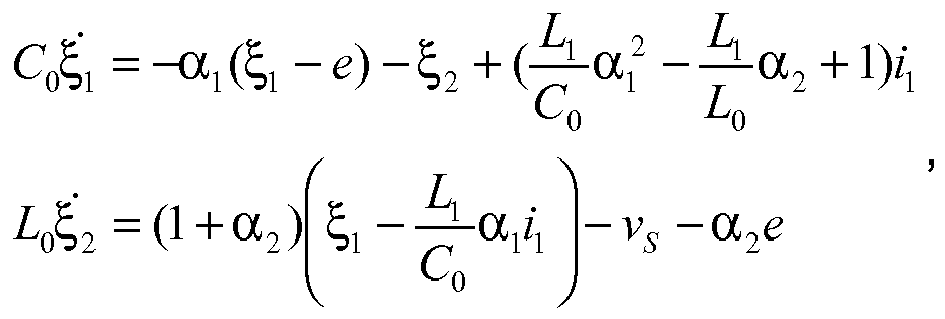
wobei ξ1 und ξ2 Beobachterzustände sind, L1 die umrichterseitige Induktorinduktanz ist, C0 die Kondensatorkapazitanz ist und L0 die netzseitige Induktorinduktanz ist des LCL-Filters und ω res die natürliche Resonanzfrequenz ist und
eine netzseitige Stromschätzung (î 0) und eine Kondensatorspannungsschätzung (ν̂ C0) rekonstruiert werden nach:

wobei α1 und α2 zwei Designparameter sind, die α1 > 0 und 1+α2 > 0 erfüllen. - Ein Verfahren gemäß dem Patentanspruch 5, dadurch g e - kennzeichnet, dass die Einstellung der beiden Designparameter α1 und α2 auf eine gewünschte Bandbreite (ω BW ) basiert und die besagten Parameter folgendermaßen eingestellt werden:


- Ein Verfahren gemäß einem der Patentansprüche 1 bis 4, dadurch gekennzeichnet , dass der umrichterseitige Strom (i 1) und die Kondensatorspannung (ν C0) gemessen werden und der netzseitige Strom (i 0) geschätzt wird, indem ein Beobachter verwendet wird, wobei
die Beobachterdynamik wie folgt gegeben wird:
wobei ξ1 ein Beobachterkoeffizient ist, C0 die Kondensatorkapazitanz ist und L0 die netzseitige Induktorinduktanz des LCL-Filters ist und ω res die natürliche Resonanzfrequenz ist und
eine netzseitige Stromschätzung (î 0) wie folgt rekonstruiert wird:
wobei α1 ein Designparameter ist. - Ein Verfahren gemäß dem Patentanspruch 7 dadurch g e - kennzeichnet, dass die Einstellung des Designparameters α1 auf eine gewünschte Bandbreite (ω BW ) basiert und der besagte Parameter wie folgt eingestellt wird:

wobei λ1 der Pol der Beobachterdynamik ist. - Ein Verfahren gemäß einem der Patentansprüche 1 bis 4, dadurch gekennzeichnet, dass der netzseitige Strom (i 0) und die Kondensatorspannung (ν C0) gemessen werden und der umrichterseitige Strom (i 1) geschätzt wird, indem ein Beobachter verwendet wird, wobei
die Beobachterdynamik wie folgt gegeben wird:
wobei ξ1 ein Beobachterkoeffizient ist, C 0 die Kondensatorkapazitanz ist und L1 die umrichterseitige Induktorinduktanz des LCL-Filters ist und ω res die natürliche Resonanzfrequenz ist und
eine netzseitige Stromschätzung (î 0) wie folgt rekonstruiert wird: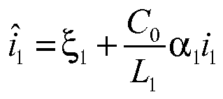
wobei α1 ein Designparameter ist. - Ein Verfahren gemäß dem Patentanspruch 9, dadurch gekennzeichnet, dass die Einstellung des Designparameters α1 auf eine gewünschte Bandbreite (ω BW ) basiert und der besagte Parameter wie folgt eingestellt wird:

wobei λ1 der Pol der Beobachterdynamik ist. - Ein Verfahren gemäß einem der Patentansprüche 1 bis 10 dadurch gekennzeichnet, dass das Bilden eines Injektionsterms Folgendes aufweist:den netzseitigen Stromdifferenzterm (ĩ 0) mit einer Konstanten R 0 multiplizieren,den umrichterseitgen Stromdifferenzterm (ĩ 1) mit einer Konstanten R1 multiplizieren,den Kondensatorspannungsdifferenzterm (ṽ C0) mit einer Konstanten R 2 multiplizieren undden Injektionsterm durch Addieren der Produkte bilden.
- Ein Verfahren gemäß dem Patentanspruch 11, dadurch g e - kennzeichnet, dass die Konstanten wie folgt definiert sind:

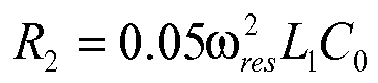

wobei L1 die umrichterseitige Induktorinduktanz ist, C0 die Kondensatorkapazitanz ist und L0 die netzseitige Induktorinduktanz des LCL-Filters ist und ω res die natürliche Resonanzfrequenz ist. - Ein Verfahren gemäß einem der Patentansprüche 1 bis 12 dadurch gekennzeichnet, dass das Bilden der Schätzung des harmonischen Verzerrungsterms (φ̂) die Summierung von k harmonischen Komponenten (φ̂1 - φ̂ k ) umfasst.
- Ein Verfahren gemäß dem Patentanspruch 1 dadurch g e - kennzeichnet, dass die fundamentale Frequenz (ω0) der Netzspannung bekannt ist und das Bilden einer harmonischen Komponente mit einer Indexzahl k (φ̂ k ) Folgendes umfasst:einen Wert für ein Quadraturbegleitsignal (ψ̂ k ) bestimmen, indem das Produkt des entgegengesetzten Wertes der harmonischen Komponente (φ̂ k ) und der fundamentalen Frequenz (ω0) der Netzspannung multipliziert mit dem Wert der Indexzahl k integriert wird,das Produkt des Quadraturbegleitsignals (ψ̂ k ) und der fundamentalen Frequenz der Netzspannung (ω0) multipliziert mit der fundamentalen Frequenz (ω0) zum Produkt der netzseitigen Stromdifferenz (ĩ 0) und dem Designparameter (γ k ) addieren,den Wert der harmonischen Komponente (φ̂ k ) bestimmen, indem die Summe der Addition integriert wird.
- Ein Verfahren gemäß dem Patentanspruch 14 dadurch g e - kennzeichnet, dass der Designparameter (γ k ) als γ k = 2.2/T kr , festgesetzt ist, wobei Tkr die gewünschte Ansprechzeit für jede kth harmonische Komponente ist, geschätzt zwischen 10% und 90% von einer Einstellzeit der Amplitude der entsprechenden sinusoidalen Störung.
- Ein Verfahren gemäß einem der Patentansprüche 1 bis 15 dadurch gekennzeichnet, dass die Injektionsspannung (e) durch Subtraktion des geschätzten harmonischen Verzerrungsterrms (φ̂) und des Injektionsterms von der Netzspannung (ṽS ) gebildet wird.
- Ein einphasiger netzgekoppelter Spannungsquellenumrichter, der adaptiert ist, an einen LCL-Filter angeschlossen zu werden, wobei der Umrichter Mittel aufweist zum Messen einer Netzspannung (ν S ) und mindestens ein Signal in einer Gruppe von Signalen, die Folgendes aufweisen: einen netzseitigen Strom (i 0), einen umrichterseitigen Strom (i 1) und eine Kondensatorspannung (v C0), dadurch gekennzeichnet, dass der Umrichter weiterhin Folgendes aufweist:Mittel, um die fundamentale Komponente (vS ,1) der Netzspannung (vS ) zu schätzen,Mittel, um eine netzseitige Stromreferenz


 Mittel, um Schätzungen der nicht gemessenen Signale in der besagten Gruppe von Signalen zu bilden,Mittel, um einen netzseitigen Stromdifferenzterm (ĩ 0), einem umrichterseitigen Sromdifferenzterm (ĩ 1) und einem Kondensatorspannungsdifferenzterm (ṽ C0) von den Differenzen zwischen den Referenzen und den gemessenen/geschätzten Werten der besagten Signale zu bilden,Mittel, um einem Injektionsterm zur Dämpfung der Resonanz des LCL-Filters zu bilden, indem ein aktiver Dämpfinjektionsmechanismus (ADI) verwendet wird, indem der netzseitige Stromdifferenzterm (ĩ 0 ), der umrichterseitige Stromdifferenzterm (ĩ 1) und der Kondensatorspannungsdifferenzterm (ṽ C0) verwendet werden,Mittel, um eine Schätzung eines harmonischen Verzerrungsterms (φ̂) zu bilden, indem der netzseitige Stromdifferenzterm (ĩ 0) verwendet wird,Mittel, um die Output-Spannung (e) des Umrichters auf der Basis der Netzspannung, des gebildeten Injektionsterms und der gebildeten Schätzung des harmonischen Verzerrungsterms (φ̂) zu steuern, um einen netzseitigen (i 0) Strom entsprechend der Stromreferenz zu produzieren.
Priority Applications (3)
| Application Number | Priority Date | Filing Date | Title |
|---|---|---|---|
| EP10154113A EP2362515B1 (de) | 2010-02-19 | 2010-02-19 | Steuerungsverfahren für netzgekoppelten Einzelphasen-LCL-Umrichter |
| US13/030,501 US8553434B2 (en) | 2010-02-19 | 2011-02-18 | Control method for single-phase grid-connected LCL inverter |
| CN201110042838.3A CN102163843B (zh) | 2010-02-19 | 2011-02-21 | 用于单相并网lcl逆变器的控制方法 |
Applications Claiming Priority (1)
| Application Number | Priority Date | Filing Date | Title |
|---|---|---|---|
| EP10154113A EP2362515B1 (de) | 2010-02-19 | 2010-02-19 | Steuerungsverfahren für netzgekoppelten Einzelphasen-LCL-Umrichter |
Publications (3)
| Publication Number | Publication Date |
|---|---|
| EP2362515A1 EP2362515A1 (de) | 2011-08-31 |
| EP2362515A9 EP2362515A9 (de) | 2011-11-23 |
| EP2362515B1 true EP2362515B1 (de) | 2012-07-25 |
Family
ID=42272148
Family Applications (1)
| Application Number | Title | Priority Date | Filing Date |
|---|---|---|---|
| EP10154113A Not-in-force EP2362515B1 (de) | 2010-02-19 | 2010-02-19 | Steuerungsverfahren für netzgekoppelten Einzelphasen-LCL-Umrichter |
Country Status (3)
| Country | Link |
|---|---|
| US (1) | US8553434B2 (de) |
| EP (1) | EP2362515B1 (de) |
| CN (1) | CN102163843B (de) |
Families Citing this family (65)
| Publication number | Priority date | Publication date | Assignee | Title |
|---|---|---|---|---|
| US8405456B2 (en) | 2009-03-31 | 2013-03-26 | Quantance, Inc. | High speed power supply system |
| JP2014508499A (ja) * | 2011-03-11 | 2014-04-03 | ユタ ステート ユニバーシティ | 非対称電圧相殺技術を使ってlclコンバータを制御する方法および装置 |
| FR2982680B1 (fr) | 2011-11-15 | 2013-11-22 | Schneider Toshiba Inverter | Procede et systeme de commande pour corriger les tensions a appliquer a une charge electrique |
| US8773873B2 (en) | 2011-12-15 | 2014-07-08 | General Electric Company | Methods and systems for operating a power converter |
| US8952753B2 (en) | 2012-02-17 | 2015-02-10 | Quantance, Inc. | Dynamic power supply employing a linear driver and a switching regulator |
| US8890502B2 (en) * | 2012-02-17 | 2014-11-18 | Quantance, Inc. | Low-noise, high bandwidth quasi-resonant mode switching power supply |
| EP2634909B1 (de) * | 2012-03-02 | 2017-02-15 | ABB Research Ltd. | Verfahren zur Steuerung einer netzgekoppelten Hochsetz-Tiefsetz-Stromzwischenkreis- Vollbrücken-Kaskade für Photovoltaic Anwendunden und Vorrichtung |
| CN102594106B (zh) * | 2012-03-09 | 2014-05-28 | 江苏大学 | 一种并网逆变器电压背景谐波的抑制方法 |
| EP2672621B1 (de) * | 2012-06-07 | 2019-01-23 | ABB Research Ltd. | Verfahren zur Nullsystemdämpfung und Spannungssymmetrierung in einem Dreipunktumrichter mit geteiltem Zwischenkreis und virtuell geerdetem LCL Filter |
| CN102857133B (zh) * | 2012-09-17 | 2015-03-25 | 广西电网公司电力科学研究院 | 单相单级光伏逆变器的电流控制方法及电流控制系统 |
| CN103050975B (zh) * | 2012-12-04 | 2015-06-24 | 国网智能电网研究院 | 一种用于高压大容量电压源变流器的参数设计方法 |
| US20140160811A1 (en) * | 2012-12-10 | 2014-06-12 | University Of Macau | Railway power conditioner for co-phase traction supply system |
| CN103094924A (zh) * | 2013-01-04 | 2013-05-08 | 广西电网公司电力科学研究院 | 基于无锁相环实现电网同步基准正弦的方法及其装置 |
| CN104038042B (zh) * | 2013-03-04 | 2016-12-28 | 珠海格力电器股份有限公司 | 交错式功率因数校正电路及其控制方法 |
| US9559581B2 (en) | 2013-04-17 | 2017-01-31 | The Regents Of The University Of Michigan | Single phase bi-directional AC-DC converter with reduced passive components size and common mode electro-magnetic interference |
| US10826322B2 (en) * | 2013-06-14 | 2020-11-03 | Abb Schweiz Ag | Systems and methods for grid interactive UPS |
| CN103414325B (zh) * | 2013-07-19 | 2015-11-25 | 合肥工业大学 | 一种并网逆变器llcl滤波器的参数设计方法 |
| CN103475029B (zh) * | 2013-09-27 | 2015-04-08 | 重庆大学 | 基于极点配置的三相lcl型并网逆变器控制系统及方法 |
| CN103956776B (zh) * | 2013-11-05 | 2017-04-19 | 广东工业大学 | 一种单相电压源型逆变电源的并网方法 |
| CN103560690B (zh) * | 2013-11-07 | 2015-07-01 | 湖南大学 | 一种单相lcl型并网逆变器谐波阻尼控制方法 |
| EP2881811B1 (de) | 2013-12-06 | 2018-08-01 | General Electric Technology GmbH | Steuerungsvorrichtung für einen spannungsgespeisten Umrichter mit einem redundanten System bestehend aus zwei Steuervorrichtungen |
| US9537424B2 (en) * | 2014-04-01 | 2017-01-03 | Majid Pahlevaninezhad | DC-bus controller for grid-connected DC/AC converters |
| CN103887822B (zh) * | 2014-04-03 | 2015-12-30 | 湖南大学 | 一种lcl型单相并网逆变器功率控制及有源阻尼优化方法 |
| EP3262741B1 (de) * | 2015-02-25 | 2019-07-10 | ABB Schweiz AG | Modellprädiktive schwingungsdämpfung in einem elektrischen wandlersystem |
| CN104716817B (zh) * | 2015-03-25 | 2017-06-16 | 国网浙江省电力公司电力科学研究院 | 一种基于多绕组变压器的变流器有源阻尼控制系统及方法 |
| EP3096429B1 (de) * | 2015-05-22 | 2019-12-11 | ABB Schweiz AG | Identifizierung von lcl-filter-parametern |
| CN107271814B (zh) * | 2015-06-16 | 2019-12-03 | 深圳市深电能售电有限公司 | 一种获得负荷非线性函数的方法 |
| CN105244919B (zh) * | 2015-08-07 | 2017-09-01 | 湖南大学 | 一种lcl型逆变器的鲁棒延时补偿并网控制方法 |
| CN105140924B (zh) * | 2015-09-24 | 2017-07-18 | 上海电力学院 | 一种混合型有源滤波器的非线性控制器设计方法 |
| CN105490297B (zh) * | 2015-11-17 | 2019-03-12 | 如皋市协创能源科技有限公司 | 基于双逆变器群协调控制的微电网供电电压和电网电流谐波同步补偿方法 |
| CN105743123A (zh) * | 2016-04-07 | 2016-07-06 | 电子科技大学 | 一种基于lcl-lc的并网系统有源阻尼参数设计方法 |
| KR102485699B1 (ko) * | 2016-04-28 | 2023-01-05 | 엘에스일렉트릭(주) | 컨버터 시스템의 댐핑 장치 및 방법 |
| US9887642B2 (en) | 2016-05-03 | 2018-02-06 | Hossein Safamehr | Method and apparatus for estimated inductance and current feedback control of a grid-connected inverter with nonlinear inductor |
| CN106094509B (zh) * | 2016-06-22 | 2019-12-06 | 广东电网有限责任公司电力科学研究院 | 一种lcr滤波控制方法及装置 |
| CN106154826A (zh) * | 2016-06-22 | 2016-11-23 | 广东电网有限责任公司电力科学研究院 | 一种对高阶对象过程信号降价2阶的方法及装置 |
| CN106487039A (zh) * | 2016-09-14 | 2017-03-08 | 杭州电子科技大学 | 一种适用于畸变电网的锁相技术 |
| CN106684918B (zh) * | 2017-03-10 | 2018-11-20 | 湖南大学 | 一种lcl逆变器弱阻尼谐振抑制与功率快速调节方法 |
| CN108390413B (zh) * | 2018-04-24 | 2021-02-26 | 华北电力大学(保定) | 一种分布式光伏对交直流混合微电网适应能力改善方法 |
| KR102109575B1 (ko) * | 2018-05-31 | 2020-05-12 | 엘에스일렉트릭(주) | 인버터 제어장치 |
| CN109004649B (zh) * | 2018-06-29 | 2021-12-28 | 南京理工大学 | 一种基于有源阻尼的lcl滤波器谐振抑制装置及方法 |
| CN108900102B (zh) * | 2018-08-15 | 2020-04-03 | 西北工业大学 | 基于类数字陷波器的网侧电流反馈lcl型并网逆变器谐振的有源阻尼方法 |
| FR3086117B1 (fr) * | 2018-09-18 | 2020-12-11 | Schneider Electric Ind Sas | Procede de controle d'un generateur |
| CN109557365B (zh) * | 2018-10-12 | 2021-07-02 | 西安电子科技大学 | 电网电压频率和相角检测方法及系统、单相电网检测系统 |
| CN109167361A (zh) * | 2018-10-17 | 2019-01-08 | 东北大学 | 一种lcl型三相并联有源电力滤波器的新型控制方法 |
| CN109888822B (zh) * | 2019-02-28 | 2023-02-03 | 南京工程学院 | 基于滑模控制的lcl型并网三相逆变器控制方法和系统 |
| CN110277798B (zh) * | 2019-06-13 | 2022-12-13 | 湖南工业大学 | 一种基于lcl型光伏逆变器的pir优化控制方法 |
| CN110311416B (zh) * | 2019-06-14 | 2020-09-01 | 合肥工业大学 | 基于状态反馈的锁相环带宽自适应并网逆变器控制方法 |
| CN110323749B (zh) * | 2019-07-31 | 2023-03-10 | 哈尔滨工业大学 | Lcl滤波器并网逆变器的干扰抑制方法 |
| CN110445143B (zh) * | 2019-09-06 | 2021-06-29 | 集美大学 | 一种lcl型并网逆变器的有源阻尼方法 |
| CN112701941B (zh) * | 2019-10-21 | 2022-04-05 | 广东美的白色家电技术创新中心有限公司 | 逆变器的补偿方法、装置以及电器设备、存储介质 |
| CN110854858A (zh) * | 2019-10-29 | 2020-02-28 | 国网江苏省电力有限公司盐城供电分公司 | 一种基于电流分析的谐波补偿装置的补偿方法 |
| CN110867856A (zh) * | 2019-11-28 | 2020-03-06 | 国网河南省电力公司驻马店供电公司 | 考虑vsc系统谐波稳定条件下的lcl滤波器参数优化方法 |
| KR102367501B1 (ko) * | 2020-04-03 | 2022-02-25 | 전북대학교산학협력단 | 계통 연계형 전력변환장치의 제어장치 |
| CN111521870B (zh) * | 2020-06-01 | 2022-10-21 | 深圳市英威腾电气股份有限公司 | 并网变流设备的谐振频率辨识方法、装置、设备及介质 |
| US11177732B1 (en) | 2020-09-04 | 2021-11-16 | Rockwell Automation Technologies, Inc. | Dynamic resonance control for grid-tied power converters |
| CN112532096B (zh) * | 2020-12-03 | 2022-09-23 | 南京理工大学 | 一种适应弱电网的lcl型逆变器并网装置及方法 |
| CN112653343B (zh) * | 2020-12-12 | 2022-04-29 | 中南大学 | 一种lcl型并网单逆变器电流反馈有源阻尼方法 |
| CN112994497B (zh) * | 2021-02-06 | 2022-03-08 | 东南大学 | 一种反馈有源阻尼的控制系统及其控制方法 |
| CN113644654B (zh) * | 2021-05-10 | 2023-10-17 | 闽南理工学院 | 一种基于lcl有源滤波器网侧电流反馈的有源阻尼方法 |
| CN113381592B (zh) * | 2021-05-14 | 2023-03-14 | 西安理工大学 | 逆变器自适应谐振抑制的电容电流反馈系数求取方法 |
| CN113517695A (zh) * | 2021-06-23 | 2021-10-19 | 天津滨电电力工程有限公司 | 提高柔性微电网电能质量的自适应电压电流协同控制器 |
| CN115864883B (zh) * | 2022-03-31 | 2023-07-11 | 国网湖北省电力公司宜昌市高新区供电公司 | 一种lcl并网逆变器装置及并网电流谐波削弱方法 |
| CN115085251B (zh) * | 2022-05-27 | 2025-12-23 | 合肥工业大学 | Lcl并网电流反馈有源阻尼控制方法及系统 |
| KR20250091187A (ko) * | 2022-08-18 | 2025-06-20 | 아리엘 싸이언티픽 이노베이션스 엘티디. | 프론트 엔드 싱글 스테이지 스텝 업 스텝 다운 3 레벨 인버터 |
| CN116633126B (zh) * | 2023-07-24 | 2023-10-17 | 成都希望森兰智能制造有限公司 | 一种无网压传感器的变频器老化系统功率因数控制方法 |
Family Cites Families (10)
| Publication number | Priority date | Publication date | Assignee | Title |
|---|---|---|---|---|
| US5198972A (en) * | 1992-01-03 | 1993-03-30 | The United States Of America As Represented By The Secretary Of The Air Force | Turn-off switch phase control with improved ripple and power factor |
| DE19532142A1 (de) * | 1995-08-31 | 1997-03-06 | Siemens Ag | Verfahren und Vorrichtung zur Regelung eines vierdimensionalen Vektors einer Strecke mittels eines wertediskreten Stellgliedes mit begrenzter Schaltfrequenz |
| US5818208A (en) * | 1996-12-19 | 1998-10-06 | Abb Power T&D Company Inc. | Flicker controllers using voltage source converters |
| US6545887B2 (en) * | 1999-08-06 | 2003-04-08 | The Regents Of The University Of California | Unified constant-frequency integration control of three-phase power factor corrected rectifiers, active power filters and grid-connected inverters |
| EP1842281B1 (de) * | 2005-01-25 | 2016-07-13 | ABB Schweiz AG | Verfahren und vorichtung zum betrieb einer umrichterschaltung mit einem lcl-filter |
| US7626836B2 (en) * | 2005-10-26 | 2009-12-01 | Rockwell Automation Technologies, Inc. | Method and apparatus for adjustable voltage/adjustable frequency inverter control |
| US7511385B2 (en) * | 2005-11-11 | 2009-03-31 | Converteam Ltd | Power converters |
| DE502006007342D1 (de) * | 2005-11-21 | 2010-08-12 | Abb Schweiz Ag | Verfahren zum betrieb einer umrichterschaltung sowie vorrichtung zur durchführung des verfahrens |
| AT504200B1 (de) * | 2006-09-04 | 2010-05-15 | Fronius Int Gmbh | Verfahren zur regelung von wechselrichtern |
| EP2062346A1 (de) * | 2006-09-15 | 2009-05-27 | ABB Schweiz AG | Verfahren zum betrieb einer umrichterschaltung sowie vorrichtung zur durchführung des verfahrens |
-
2010
- 2010-02-19 EP EP10154113A patent/EP2362515B1/de not_active Not-in-force
-
2011
- 2011-02-18 US US13/030,501 patent/US8553434B2/en not_active Expired - Fee Related
- 2011-02-21 CN CN201110042838.3A patent/CN102163843B/zh not_active Expired - Fee Related
Also Published As
| Publication number | Publication date |
|---|---|
| CN102163843B (zh) | 2014-07-30 |
| US8553434B2 (en) | 2013-10-08 |
| EP2362515A1 (de) | 2011-08-31 |
| EP2362515A9 (de) | 2011-11-23 |
| CN102163843A (zh) | 2011-08-24 |
| US20110221420A1 (en) | 2011-09-15 |
Similar Documents
| Publication | Publication Date | Title |
|---|---|---|
| EP2362515B1 (de) | Steuerungsverfahren für netzgekoppelten Einzelphasen-LCL-Umrichter | |
| Xu et al. | Overview of SOGI-based single-phase phase-locked loops for grid synchronization under complex grid conditions | |
| Espí et al. | An adaptive robust predictive current control for three-phase grid-connected inverters | |
| Karimi-Ghartema | Enhanced phase-locked loop structures for power and energy applications | |
| Saleem et al. | Resonance damping for an LCL filter type grid-connected inverter with active disturbance rejection control under grid impedance uncertainty | |
| US8929108B2 (en) | Method and apparatus for controlling a grid-connected converter | |
| Abusara et al. | Improved droop control strategy for grid-connected inverters | |
| Maccari et al. | Robust ℌ∞ control for grid connected PWM inverters with LCL filters | |
| CN110323749A (zh) | Lcl滤波器并网逆变器的干扰抑制方法 | |
| Mahdian-Dehkordi et al. | Nonlinear adaptive control of grid-connected three-phase inverters for renewable energy applications | |
| Vedantham et al. | Fuzzy logic gain‐tuned adaptive second‐order GI‐based multi‐objective control for reliable operation of grid‐interfaced photovoltaic system | |
| Peña et al. | RLC passive damped LCL single-phase voltage source inverter with capability to operate in grid-connected and islanded modes: design and control strategy | |
| Miret et al. | PI‐based controller for low‐power distributed inverters to maximise reactive current injection while avoiding over voltage during voltage sags | |
| Huang et al. | Virtual RLC active damping for grid-connected inverters with LCL filters | |
| Gong et al. | Observer-based second-order sliding mode current controller for thyristor-controlled LC-coupling hybrid active power filter | |
| Xue et al. | Adaptive active damping method of grid-connected inverter based on model predictive control in weak grid | |
| Yadav et al. | Current harmonic mitigation in grid tied solar photovoltaic system via PRES | |
| Liu et al. | Robust damping method for voltage source converter with LCL-type filter under weak grid conditions | |
| Escobar et al. | Control of single-phase inverter connected to the grid through an LCL filter | |
| Huang et al. | The overview of damping methods for three-phase grid-tied inverter with LLCL-filter | |
| Fallah et al. | Compensation of distortions in VSC-based DC–AC power systems using a modified vector control method | |
| Asbafkan et al. | Frequency adaptive repetitive control of grid connected inverter for wind turbine applications | |
| Alves et al. | A procedure to design damping virtual impedance on grid-forming voltage source converters with lcl filters | |
| Chandran et al. | Novel bandpass filter‐based control strategy for control of a hydro‐PV‐BES supported isolated MG | |
| Ko et al. | A new PLL system using full order observer and PLL system modeling in a single phase grid-connected inverter |
Legal Events
| Date | Code | Title | Description |
|---|---|---|---|
| PUAI | Public reference made under article 153(3) epc to a published international application that has entered the european phase |
Free format text: ORIGINAL CODE: 0009012 |
|
| AK | Designated contracting states |
Kind code of ref document: A1 Designated state(s): AT BE BG CH CY CZ DE DK EE ES FI FR GB GR HR HU IE IS IT LI LT LU LV MC MK MT NL NO PL PT RO SE SI SK SM TR |
|
| AX | Request for extension of the european patent |
Extension state: AL BA RS |
|
| 17P | Request for examination filed |
Effective date: 20111017 |
|
| GRAP | Despatch of communication of intention to grant a patent |
Free format text: ORIGINAL CODE: EPIDOSNIGR1 |
|
| RIC1 | Information provided on ipc code assigned before grant |
Ipc: H02J 3/01 20060101AFI20111212BHEP |
|
| GRAS | Grant fee paid |
Free format text: ORIGINAL CODE: EPIDOSNIGR3 |
|
| RAP1 | Party data changed (applicant data changed or rights of an application transferred) |
Owner name: ABB RESEARCH LTD |
|
| RIN1 | Information on inventor provided before grant (corrected) |
Inventor name: ESCOBAR, GERARDO Inventor name: SERPA, LEONARDO-AUGUSTO Inventor name: COCCIA, ANTONIO Inventor name: PETTERSSON, SAMI Inventor name: PAAKKINEN, MIKKO |
|
| GRAA | (expected) grant |
Free format text: ORIGINAL CODE: 0009210 |
|
| AK | Designated contracting states |
Kind code of ref document: B1 Designated state(s): AT BE BG CH CY CZ DE DK EE ES FI FR GB GR HR HU IE IS IT LI LT LU LV MC MK MT NL NO PL PT RO SE SI SK SM TR |
|
| REG | Reference to a national code |
Ref country code: GB Ref legal event code: FG4D |
|
| REG | Reference to a national code |
Ref country code: CH Ref legal event code: EP |
|
| REG | Reference to a national code |
Ref country code: AT Ref legal event code: REF Ref document number: 568039 Country of ref document: AT Kind code of ref document: T Effective date: 20120815 Ref country code: IE Ref legal event code: FG4D |
|
| REG | Reference to a national code |
Ref country code: DE Ref legal event code: R096 Ref document number: 602010002261 Country of ref document: DE Effective date: 20120920 |
|
| REG | Reference to a national code |
Ref country code: NL Ref legal event code: VDEP Effective date: 20120725 |
|
| REG | Reference to a national code |
Ref country code: AT Ref legal event code: MK05 Ref document number: 568039 Country of ref document: AT Kind code of ref document: T Effective date: 20120725 |
|
| REG | Reference to a national code |
Ref country code: LT Ref legal event code: MG4D Effective date: 20120725 |
|
| PG25 | Lapsed in a contracting state [announced via postgrant information from national office to epo] |
Ref country code: HR Free format text: LAPSE BECAUSE OF FAILURE TO SUBMIT A TRANSLATION OF THE DESCRIPTION OR TO PAY THE FEE WITHIN THE PRESCRIBED TIME-LIMIT Effective date: 20120725 Ref country code: CY Free format text: LAPSE BECAUSE OF FAILURE TO SUBMIT A TRANSLATION OF THE DESCRIPTION OR TO PAY THE FEE WITHIN THE PRESCRIBED TIME-LIMIT Effective date: 20120725 Ref country code: NO Free format text: LAPSE BECAUSE OF FAILURE TO SUBMIT A TRANSLATION OF THE DESCRIPTION OR TO PAY THE FEE WITHIN THE PRESCRIBED TIME-LIMIT Effective date: 20121025 Ref country code: AT Free format text: LAPSE BECAUSE OF FAILURE TO SUBMIT A TRANSLATION OF THE DESCRIPTION OR TO PAY THE FEE WITHIN THE PRESCRIBED TIME-LIMIT Effective date: 20120725 Ref country code: LT Free format text: LAPSE BECAUSE OF FAILURE TO SUBMIT A TRANSLATION OF THE DESCRIPTION OR TO PAY THE FEE WITHIN THE PRESCRIBED TIME-LIMIT Effective date: 20120725 Ref country code: BE Free format text: LAPSE BECAUSE OF FAILURE TO SUBMIT A TRANSLATION OF THE DESCRIPTION OR TO PAY THE FEE WITHIN THE PRESCRIBED TIME-LIMIT Effective date: 20120725 Ref country code: IS Free format text: LAPSE BECAUSE OF FAILURE TO SUBMIT A TRANSLATION OF THE DESCRIPTION OR TO PAY THE FEE WITHIN THE PRESCRIBED TIME-LIMIT Effective date: 20121125 |
|
| PG25 | Lapsed in a contracting state [announced via postgrant information from national office to epo] |
Ref country code: PL Free format text: LAPSE BECAUSE OF FAILURE TO SUBMIT A TRANSLATION OF THE DESCRIPTION OR TO PAY THE FEE WITHIN THE PRESCRIBED TIME-LIMIT Effective date: 20120725 Ref country code: SE Free format text: LAPSE BECAUSE OF FAILURE TO SUBMIT A TRANSLATION OF THE DESCRIPTION OR TO PAY THE FEE WITHIN THE PRESCRIBED TIME-LIMIT Effective date: 20120725 Ref country code: GR Free format text: LAPSE BECAUSE OF FAILURE TO SUBMIT A TRANSLATION OF THE DESCRIPTION OR TO PAY THE FEE WITHIN THE PRESCRIBED TIME-LIMIT Effective date: 20121026 Ref country code: PT Free format text: LAPSE BECAUSE OF FAILURE TO SUBMIT A TRANSLATION OF THE DESCRIPTION OR TO PAY THE FEE WITHIN THE PRESCRIBED TIME-LIMIT Effective date: 20121126 Ref country code: LV Free format text: LAPSE BECAUSE OF FAILURE TO SUBMIT A TRANSLATION OF THE DESCRIPTION OR TO PAY THE FEE WITHIN THE PRESCRIBED TIME-LIMIT Effective date: 20120725 Ref country code: SI Free format text: LAPSE BECAUSE OF FAILURE TO SUBMIT A TRANSLATION OF THE DESCRIPTION OR TO PAY THE FEE WITHIN THE PRESCRIBED TIME-LIMIT Effective date: 20120725 |
|
| PG25 | Lapsed in a contracting state [announced via postgrant information from national office to epo] |
Ref country code: NL Free format text: LAPSE BECAUSE OF FAILURE TO SUBMIT A TRANSLATION OF THE DESCRIPTION OR TO PAY THE FEE WITHIN THE PRESCRIBED TIME-LIMIT Effective date: 20120725 |
|
| PG25 | Lapsed in a contracting state [announced via postgrant information from national office to epo] |
Ref country code: CZ Free format text: LAPSE BECAUSE OF FAILURE TO SUBMIT A TRANSLATION OF THE DESCRIPTION OR TO PAY THE FEE WITHIN THE PRESCRIBED TIME-LIMIT Effective date: 20120725 Ref country code: RO Free format text: LAPSE BECAUSE OF FAILURE TO SUBMIT A TRANSLATION OF THE DESCRIPTION OR TO PAY THE FEE WITHIN THE PRESCRIBED TIME-LIMIT Effective date: 20120725 Ref country code: DK Free format text: LAPSE BECAUSE OF FAILURE TO SUBMIT A TRANSLATION OF THE DESCRIPTION OR TO PAY THE FEE WITHIN THE PRESCRIBED TIME-LIMIT Effective date: 20120725 Ref country code: EE Free format text: LAPSE BECAUSE OF FAILURE TO SUBMIT A TRANSLATION OF THE DESCRIPTION OR TO PAY THE FEE WITHIN THE PRESCRIBED TIME-LIMIT Effective date: 20120725 |
|
| PG25 | Lapsed in a contracting state [announced via postgrant information from national office to epo] |
Ref country code: SK Free format text: LAPSE BECAUSE OF FAILURE TO SUBMIT A TRANSLATION OF THE DESCRIPTION OR TO PAY THE FEE WITHIN THE PRESCRIBED TIME-LIMIT Effective date: 20120725 |
|
| PLBE | No opposition filed within time limit |
Free format text: ORIGINAL CODE: 0009261 |
|
| STAA | Information on the status of an ep patent application or granted ep patent |
Free format text: STATUS: NO OPPOSITION FILED WITHIN TIME LIMIT |
|
| 26N | No opposition filed |
Effective date: 20130426 |
|
| PG25 | Lapsed in a contracting state [announced via postgrant information from national office to epo] |
Ref country code: BG Free format text: LAPSE BECAUSE OF FAILURE TO SUBMIT A TRANSLATION OF THE DESCRIPTION OR TO PAY THE FEE WITHIN THE PRESCRIBED TIME-LIMIT Effective date: 20121025 |
|
| REG | Reference to a national code |
Ref country code: DE Ref legal event code: R097 Ref document number: 602010002261 Country of ref document: DE Effective date: 20130426 |
|
| PG25 | Lapsed in a contracting state [announced via postgrant information from national office to epo] |
Ref country code: MC Free format text: LAPSE BECAUSE OF NON-PAYMENT OF DUE FEES Effective date: 20130228 |
|
| PG25 | Lapsed in a contracting state [announced via postgrant information from national office to epo] |
Ref country code: ES Free format text: LAPSE BECAUSE OF FAILURE TO SUBMIT A TRANSLATION OF THE DESCRIPTION OR TO PAY THE FEE WITHIN THE PRESCRIBED TIME-LIMIT Effective date: 20121105 |
|
| REG | Reference to a national code |
Ref country code: IE Ref legal event code: MM4A |
|
| PG25 | Lapsed in a contracting state [announced via postgrant information from national office to epo] |
Ref country code: IE Free format text: LAPSE BECAUSE OF NON-PAYMENT OF DUE FEES Effective date: 20130219 |
|
| PG25 | Lapsed in a contracting state [announced via postgrant information from national office to epo] |
Ref country code: MT Free format text: LAPSE BECAUSE OF FAILURE TO SUBMIT A TRANSLATION OF THE DESCRIPTION OR TO PAY THE FEE WITHIN THE PRESCRIBED TIME-LIMIT Effective date: 20120725 |
|
| REG | Reference to a national code |
Ref country code: CH Ref legal event code: PL |
|
| PG25 | Lapsed in a contracting state [announced via postgrant information from national office to epo] |
Ref country code: CH Free format text: LAPSE BECAUSE OF NON-PAYMENT OF DUE FEES Effective date: 20140228 Ref country code: LI Free format text: LAPSE BECAUSE OF NON-PAYMENT OF DUE FEES Effective date: 20140228 |
|
| PGFP | Annual fee paid to national office [announced via postgrant information from national office to epo] |
Ref country code: FI Payment date: 20150211 Year of fee payment: 6 |
|
| PG25 | Lapsed in a contracting state [announced via postgrant information from national office to epo] |
Ref country code: SM Free format text: LAPSE BECAUSE OF FAILURE TO SUBMIT A TRANSLATION OF THE DESCRIPTION OR TO PAY THE FEE WITHIN THE PRESCRIBED TIME-LIMIT Effective date: 20120725 |
|
| PG25 | Lapsed in a contracting state [announced via postgrant information from national office to epo] |
Ref country code: TR Free format text: LAPSE BECAUSE OF FAILURE TO SUBMIT A TRANSLATION OF THE DESCRIPTION OR TO PAY THE FEE WITHIN THE PRESCRIBED TIME-LIMIT Effective date: 20120725 |
|
| PG25 | Lapsed in a contracting state [announced via postgrant information from national office to epo] |
Ref country code: LU Free format text: LAPSE BECAUSE OF NON-PAYMENT OF DUE FEES Effective date: 20130219 Ref country code: HU Free format text: LAPSE BECAUSE OF FAILURE TO SUBMIT A TRANSLATION OF THE DESCRIPTION OR TO PAY THE FEE WITHIN THE PRESCRIBED TIME-LIMIT; INVALID AB INITIO Effective date: 20100219 Ref country code: MK Free format text: LAPSE BECAUSE OF FAILURE TO SUBMIT A TRANSLATION OF THE DESCRIPTION OR TO PAY THE FEE WITHIN THE PRESCRIBED TIME-LIMIT Effective date: 20120725 |
|
| REG | Reference to a national code |
Ref country code: FR Ref legal event code: PLFP Year of fee payment: 7 |
|
| PG25 | Lapsed in a contracting state [announced via postgrant information from national office to epo] |
Ref country code: FI Free format text: LAPSE BECAUSE OF NON-PAYMENT OF DUE FEES Effective date: 20160219 |
|
| REG | Reference to a national code |
Ref country code: FR Ref legal event code: PLFP Year of fee payment: 8 |
|
| REG | Reference to a national code |
Ref country code: FR Ref legal event code: PLFP Year of fee payment: 9 |
|
| REG | Reference to a national code |
Ref country code: DE Ref legal event code: R081 Ref document number: 602010002261 Country of ref document: DE Owner name: ABB SCHWEIZ AG, CH Free format text: FORMER OWNER: ABB RESEARCH LTD., ZUERICH, CH Ref country code: DE Ref legal event code: R081 Ref document number: 602010002261 Country of ref document: DE Owner name: MARICI HOLDINGS THE NETHERLANDS B.V., NL Free format text: FORMER OWNER: ABB RESEARCH LTD., ZUERICH, CH |
|
| REG | Reference to a national code |
Ref country code: GB Ref legal event code: 732E Free format text: REGISTERED BETWEEN 20200206 AND 20200212 |
|
| PGFP | Annual fee paid to national office [announced via postgrant information from national office to epo] |
Ref country code: IT Payment date: 20200225 Year of fee payment: 11 Ref country code: GB Payment date: 20200219 Year of fee payment: 11 |
|
| PGFP | Annual fee paid to national office [announced via postgrant information from national office to epo] |
Ref country code: FR Payment date: 20200219 Year of fee payment: 11 |
|
| REG | Reference to a national code |
Ref country code: DE Ref legal event code: R081 Ref document number: 602010002261 Country of ref document: DE Owner name: MARICI HOLDINGS THE NETHERLANDS B.V., NL Free format text: FORMER OWNER: ABB SCHWEIZ AG, BADEN, CH |
|
| PGFP | Annual fee paid to national office [announced via postgrant information from national office to epo] |
Ref country code: DE Payment date: 20210217 Year of fee payment: 12 |
|
| GBPC | Gb: european patent ceased through non-payment of renewal fee |
Effective date: 20210219 |
|
| PG25 | Lapsed in a contracting state [announced via postgrant information from national office to epo] |
Ref country code: GB Free format text: LAPSE BECAUSE OF NON-PAYMENT OF DUE FEES Effective date: 20210219 Ref country code: FR Free format text: LAPSE BECAUSE OF NON-PAYMENT OF DUE FEES Effective date: 20210228 |
|
| PG25 | Lapsed in a contracting state [announced via postgrant information from national office to epo] |
Ref country code: IT Free format text: LAPSE BECAUSE OF NON-PAYMENT OF DUE FEES Effective date: 20210219 |
|
| REG | Reference to a national code |
Ref country code: DE Ref legal event code: R119 Ref document number: 602010002261 Country of ref document: DE |
|
| PG25 | Lapsed in a contracting state [announced via postgrant information from national office to epo] |
Ref country code: DE Free format text: LAPSE BECAUSE OF NON-PAYMENT OF DUE FEES Effective date: 20220901 |