EP2362519A2 - Système et procédé pour système de conversion de puissance en une seule étape - Google Patents
Système et procédé pour système de conversion de puissance en une seule étape Download PDFInfo
- Publication number
- EP2362519A2 EP2362519A2 EP20110155418 EP11155418A EP2362519A2 EP 2362519 A2 EP2362519 A2 EP 2362519A2 EP 20110155418 EP20110155418 EP 20110155418 EP 11155418 A EP11155418 A EP 11155418A EP 2362519 A2 EP2362519 A2 EP 2362519A2
- Authority
- EP
- European Patent Office
- Prior art keywords
- power
- single stage
- load balancing
- stage inverter
- balancing unit
- Prior art date
- Legal status (The legal status is an assumption and is not a legal conclusion. Google has not performed a legal analysis and makes no representation as to the accuracy of the status listed.)
- Granted
Links
Images



Classifications
-
- H—ELECTRICITY
- H02—GENERATION; CONVERSION OR DISTRIBUTION OF ELECTRIC POWER
- H02J—ELECTRIC POWER NETWORKS; CIRCUIT ARRANGEMENTS OR SYSTEMS FOR SUPPLYING OR DISTRIBUTING ELECTRIC POWER; SYSTEMS FOR STORING ELECTRIC ENERGY
- H02J7/00—Circuit arrangements for charging or discharging batteries or for supplying loads from batteries
- H02J7/34—Parallel operation in networks using both storage and other DC sources, e.g. providing buffering
- H02J7/35—Parallel operation in networks using both storage and other DC sources, e.g. providing buffering with light sensitive cells
-
- H—ELECTRICITY
- H02—GENERATION; CONVERSION OR DISTRIBUTION OF ELECTRIC POWER
- H02J—ELECTRIC POWER NETWORKS; CIRCUIT ARRANGEMENTS OR SYSTEMS FOR SUPPLYING OR DISTRIBUTING ELECTRIC POWER; SYSTEMS FOR STORING ELECTRIC ENERGY
- H02J3/00—Circuit arrangements for AC mains or AC distribution networks
- H02J3/38—Arrangements for feeding a single network from two or more generators or sources in parallel; Arrangements for feeding already energised networks from additional generators or sources in parallel
- H02J3/381—Dispersed generators
-
- H—ELECTRICITY
- H02—GENERATION; CONVERSION OR DISTRIBUTION OF ELECTRIC POWER
- H02J—ELECTRIC POWER NETWORKS; CIRCUIT ARRANGEMENTS OR SYSTEMS FOR SUPPLYING OR DISTRIBUTING ELECTRIC POWER; SYSTEMS FOR STORING ELECTRIC ENERGY
- H02J2101/00—Supply or distribution of decentralised, dispersed or local electric power generation
- H02J2101/20—Dispersed power generation using renewable energy sources
- H02J2101/22—Solar energy
- H02J2101/24—Photovoltaics
-
- H—ELECTRICITY
- H02—GENERATION; CONVERSION OR DISTRIBUTION OF ELECTRIC POWER
- H02J—ELECTRIC POWER NETWORKS; CIRCUIT ARRANGEMENTS OR SYSTEMS FOR SUPPLYING OR DISTRIBUTING ELECTRIC POWER; SYSTEMS FOR STORING ELECTRIC ENERGY
- H02J3/00—Circuit arrangements for AC mains or AC distribution networks
- H02J3/28—Arrangements for balancing of the load in networks by storage of energy
- H02J3/32—Arrangements for balancing of the load in networks by storage of energy using batteries or super capacitors with converting means
-
- Y—GENERAL TAGGING OF NEW TECHNOLOGICAL DEVELOPMENTS; GENERAL TAGGING OF CROSS-SECTIONAL TECHNOLOGIES SPANNING OVER SEVERAL SECTIONS OF THE IPC; TECHNICAL SUBJECTS COVERED BY FORMER USPC CROSS-REFERENCE ART COLLECTIONS [XRACs] AND DIGESTS
- Y02—TECHNOLOGIES OR APPLICATIONS FOR MITIGATION OR ADAPTATION AGAINST CLIMATE CHANGE
- Y02E—REDUCTION OF GREENHOUSE GAS [GHG] EMISSIONS, RELATED TO ENERGY GENERATION, TRANSMISSION OR DISTRIBUTION
- Y02E10/00—Energy generation through renewable energy sources
- Y02E10/50—Photovoltaic [PV] energy
- Y02E10/56—Power conversion systems, e.g. maximum power point trackers
Definitions
- the invention relates generally to power conversion, and, more specifically, to a single stage power conversion system.
- Solar power generation uses photovoltaic sources to generate electricity from the sun. Multiple photovoltaic sources are electrically coupled to one another in such systems. The electricity generated by photovoltaic sources is transmitted to the power grid through one or more power electronic converters.
- the power electronic converters are commonly classified as dual stage converters and single stage converters depending on the number of stages employed to convert direct current power to alternating current power.
- Conventional single stage power conversion systems include a single stage converter connected to a controller that implements a maximum power point (MPP) algorithm to transmit maximum alternating power to the power grid from the single stage converter.
- MPP maximum power point
- a single stage power conversion system is controlled such that its performance can be compared to a stiff current source.
- the controller ensures that a direct current voltage, hereinafter DC voltage, is held at a desired value by guaranteeing that the power injected in the power grid matches the power obtained from the photovoltaic source. This is achieved by regulating a grid alternating current, hereinafter AC current, such that it follows any variation of the input power obtained from the photovoltaic source.
- Current stiff power conversion systems do not set a grid voltage. In solar applications it is desired to constantly adjust the DC voltage to extract maximum power from the solar array.
- a power conversion system includes a photovoltaic source to generate direct current (DC) power; a direct current (DC) to an alternating current (AC) single stage inverter to convert the direct current (DC) power from the photovoltaic source to alternating current (AC) power for delivery to a power grid; a load balancing unit coupled to the single stage inverter; and a controller configured to determine a maximum power point for the power conversion system, regulate an output voltage of the single stage inverter, compute a power balance difference between a power demand from the power grid and an output power of the single stage inverter obtainable at the maximum power point and control in real-time the load balancing unit based on the power balance difference.
- a method for controlling a power conversion system including a photovoltaic source to generate direct current (DC) power and a direct current (DC) to an alternating current (AC) single stage inverter to convert the direct current (DC) power from the photovoltaic source to alternating current (AC) power for delivery to a power grid.
- the method includes determining a maximum power point for the power conversion system, regulating an output voltage of the single stage inverter, computing a power balance difference between a power demand from the power grid and an output power of the single stage inverter obtainable at the maximum power point and controlling in real-time a load balancing unit based on the power balance difference.
- embodiments of the present invention include a system and method for a single stage power conversion system.
- the single stage power conversion system is designed to provide a substantially constant alternating current voltage, hereinafter AC voltage, to a power grid and to control the power balance between input power and output power.
- the voltage component of the AC power is controlled via a load balancing unit further connected to a controller.
- the controller determines a maximum power point, hereinafter MPP, for the power conversion system.
- MPP is defined as the point at which a photovoltaic source provides maximum power as an output of the photovoltaic source.
- the controller further sets the voltage component of the AC power at an output of a single stage inverter during operation.
- the controller computes a power balance difference between a power demand from the power grid and the output power of the single stage inverter obtainable at the MPP.
- the controller controls the load balancing unit in real time based on the power balance difference.
- the load balancing unit provides an adequate load balancing power to the single stage inverter such that the solar conversion unit operates at MPP and ensures substantially constant AC voltage at varying grid conditions at the output of the single stage inverter.
- the AC power is fed to a power grid which may comprise, for example, a utility grid, a mini-grid, a load, or combinations thereof.
- the AC power fed to the power grid in most conventional single stage power conversion systems is controlled via regulating a current component of the AC power. When regulating the current component of the AC power, it can be difficult to provide constant AC voltage to a power grid during changing load conditions and varying input power conditions.
- FIG. 1 is a block diagram representation of a single stage power conversion system 10 including a load balancing unit 12 to control the voltage component of the AC power fed to a power grid 14 in accordance with an embodiment of the invention.
- the power conversion system 10 includes a photovoltaic source 16, hereinafter PV source 16, to generate a direct current power, hereinafter DC power.
- the PV source 16 may include one or more photovoltaic arrays or modules fabricated via interconnecting multiple solar cells.
- the PV source 16 captures solar energy 18 and converts the solar energy 18 to the DC power.
- the DC power includes a voltage component V dc at the PV source 16.
- the DC power is transmitted to a single stage inverter 20 via a DC link 22 as an input DC in to the single stage inverter 20.
- the single stage inverter 20 comprises a three phase inverter.
- the single stage inverter 20 converts the input DC in to an alternating current power, hereinafter AC power, as an output AC out .
- the AC out is supplied to a power grid 14 via a power line 24.
- the AC out is regulated to maintain maximum yield of the power conversion system 10 by controlling the MPP of the power conversion system 10 while also providing a voltage component of the AC out .
- the load balancing unit 12 is coupled to a controller 26 which controls the load balancing unit 12 and determines the MPP of the power conversion system 10.
- the MPP is determined via a perturbation and observation method.
- the perturbation and observation method provides a method in which the voltage drawn from the solar array is perturbed and the power change is observed. If the perturbation results in an increase in power, the subsequent perturbation is made in the same direction and vice versa.
- controller 26 is shown as a discrete block for purposes of illustration, in some embodiments, the controller may include control functionality in multiple control units. In one particular example, at least a portion of controller 26 is located within DC to AC inverter 20.
- the controller 26 regulates the voltage component V ac of the output AC out .
- a voltage sensor is coupled to the power line 24, and the controller 26 computes a difference V d between the voltage component V ac and a desired regulated grid voltage V r .
- the controller 26 further compares the difference V d with a predefmed voltage difference tolerance that represents an acceptable difference in voltage component V ac and the regulated grid voltage V r . In an event of difference V d outside of the voltage difference tolerance, the controller 26 sends a control signal to the single stage inverter 20 drive the voltage component V ac towards the regulated grid voltage Vr.
- the control signal to the single stage inverter is designed to drive the output voltage towards the regulated grid voltage; however, to provide voltage matching under conditions of power imbalance, the power imbalance also needs to be addressed.
- the controller 26 is further used to compute a power balance difference (S) between the power demand from the power grid and the output power of the single stage inverter obtainable at the maximum power point. Controller 26 then controls the load balancing unit in real-time based on the power balance difference.
- the load balancing unit 12 includes an energy storage element 28.
- the energy storage element 28 includes a battery or ultra-capacitor.
- the load balancing unit 12 includes a resistor or a power dissipative element. When needed, in response to a control signal from the controller 26, the load balancing unit 12 will absorb or provide power while still allowing the controller 26 to enable the voltage V ac to be maintained at the desired reference level Vr or within the voltage difference tolerance while feeding the power grid 14 with a variable impedance characteristic and operating the power conversion system 10 at the MPP.
- the load balancing unit will be controlled to absorb power when the power demanded from the power grid is less than the output power of the single stage inverter obtainable at the maximum power point by a first power difference tolerance and will be controlled to provide power when the power demanded from the power grid is greater than the output power of the single stage inverter obtainable at the maximum power point by a second power difference tolerance (which may have the same magnitude or a different magnitude as compared with the first power different tolerance).
- the load balancing unit 12 further includes a DC to DC converter 30 including switches that may be controlled for selectively providing or absorbing the AC power at the output of the single stage inverter 20.
- FIG. 2 is a diagrammatic representation of another exemplary configuration of the single stage power conversion system 10 including a load balancing unit 12 that includes an energy storage element 28 coupled to a DC to AC converter 32 to regulate the voltage and control the power fed to the power grid 14 in accordance with an embodiment of the invention.
- the load balancing unit 12 is coupled to the power line 24 between the single stage converter 20 and power grid 14.
- the controller 26 regulates the voltage component V ac to match the regulated grid voltage Vr, computes the power balance difference S between the power demand from the power grid and the output power of the single stage inverter obtainable at the maximum power point, and controls the load balancing unit in real-time based on the power balance difference S.
- the load balancing unit 12 In response to a control signal from the controller 26, the load balancing unit 12 will absorb or provide power allowing the controller 26 to enable the voltage V ac to be maintained at the desired reference level Vr or desired within the tolerance band V th while feeding the power grid 14 with a variable impedance characteristic and operating the power conversion system 10 at the MPP.
- the load balancing unit 12 includes DC to AC converter 32.
- FIG. 3 is a diagrammatic representation of an exemplary configuration of a single stage power conversion system 10 including a load balancing unit 12 comprising a variable load 42 coupled to the DC link 22 between a PV source 16 and a single stage inverter 20 in accordance with an embodiment of the invention.
- the variable load 42 includes a pump or a heater.
- the variable load 42 may be coupled to the DC link 22 via at least one switching device 44. As described above in FIG.
- the controller 26 regulates the voltage component V ac to match the regulated grid voltage Vr, computes the power balance difference S between the power demand from the power grid and the output power of the single stage inverter obtainable at the maximum power point, and controls the load balancing unit in real-time based on the power balance difference.
- the controller 26 sends a control signal to the at least one switching device 44 to switch to a closed state and provide an adequate load balancing power generated by the variable load 42 at the DC link 22. This will allow the controller 26 to enable the voltage V ac to be maintained at the desired reference level Vr or within the tolerance band V th while feeding the power grid 14 with a variable impedance characteristic and operating the power conversion system 10 at the MPP.
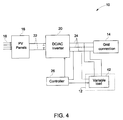
- FIG. 4 is a diagrammatic representation of another exemplary configuration of the single stage power conversion system 10 including a variable load 42 coupled to a power line 24 between the single stage inverter 20 and the power grid 14 in accordance with an embodiment of the invention.
- the controller 26 regulates the voltage component V ac to match the regulated grid voltage Vr, computes the power balance difference S between the power demand from the power grid and the output power of the single stage inverter obtainable at the maximum power point, and controls the load balancing unit in real-time based on the power balance difference S.
- the controller 26 in an event of the power balance difference S exceeding a power balance difference tolerance, sends a control signal to the variable load 42 to absorb or provide power allowing the controller 26 to enable the voltage V ac to be maintained at the desired reference level or within the tolerance band V th while feeding the power grid 14 with a variable impedance characteristic and operating the single stage power conversion system 10 at the MPP.
- FIG. 5 is a flow chart representing the steps involved in a method for controlling a power conversion system including a photovoltaic source to generate direct current (DC) power and a direct current (DC) to an alternating current (AC) single stage inverter to convert the direct current (DC) power from the photovoltaic source to alternating current (AC) power for delivery to a power grid in accordance with an embodiment of the invention.
- the method 50 includes determining a maximum power point (MPP) for the power conversion system in step 52.
- MPP maximum power point
- an output voltage of the single stage inverter is regulated in step 54.
- a power balance difference is computed between a power demand from the power grid and an output power of the single stage inverter obtainable at maximum power point in step 56.
- a load balancing unit is controlled in real time based on the power balance difference in step 58.
- the load balancing unit is coupled to a DC link between the photovoltaic source and the single stage inverter in a parallel connection.
- the load balancing unit may be coupled to a power line between the single stage inverter and the power grid.
- the load balancing unit includes an energy storage element or a variable load.
- the various embodiments of a power conversion system described above provide a voltage controlled single stage power conversion system including a load balancing unit.
- the load balancing unit provides a load balancing voltage to a single stage inverter to ensure AC power at the MPP is fed to the power grid at a regulated voltage.
- these techniques enable a voltage source controlled power conversion system that is particular useful for weak grid and islanded conditions.
- existing single stage power conversion systems can be upgraded to operate in weak grid environments by adding load balancing units and modifying control systems as described herein.
- the DC to AC converter with respect to one embodiment can be adapted for use with the variable load described with respect to another embodiment of the invention to generate power at maximum power point in the voltage source controlled single stage power conversion system.
- the various features described, as well as other known equivalents for each feature may be mixed and matched by one of ordinary skill in this art to construct additional systems and techniques in accordance with principles of this disclosure.
Landscapes
- Engineering & Computer Science (AREA)
- Power Engineering (AREA)
- Inverter Devices (AREA)
- Supply And Distribution Of Alternating Current (AREA)
Applications Claiming Priority (1)
| Application Number | Priority Date | Filing Date | Title |
|---|---|---|---|
| US12/714,029 US8358031B2 (en) | 2010-02-26 | 2010-02-26 | System and method for a single stage power conversion system |
Publications (3)
| Publication Number | Publication Date |
|---|---|
| EP2362519A2 true EP2362519A2 (fr) | 2011-08-31 |
| EP2362519A3 EP2362519A3 (fr) | 2017-07-12 |
| EP2362519B1 EP2362519B1 (fr) | 2020-02-05 |
Family
ID=44063135
Family Applications (1)
| Application Number | Title | Priority Date | Filing Date |
|---|---|---|---|
| EP11155418.4A Active EP2362519B1 (fr) | 2010-02-26 | 2011-02-22 | Système et procédé pour système de conversion de puissance en une seule étape |
Country Status (5)
| Country | Link |
|---|---|
| US (1) | US8358031B2 (fr) |
| EP (1) | EP2362519B1 (fr) |
| CN (1) | CN102170241B (fr) |
| AU (1) | AU2011200794B2 (fr) |
| ES (1) | ES2774742T3 (fr) |
Cited By (10)
| Publication number | Priority date | Publication date | Assignee | Title |
|---|---|---|---|---|
| CZ304509B6 (cs) * | 2013-04-25 | 2014-06-04 | Unites Systems A.S. | Systém pro hospodaření s elektrickou energií vyrobenou fotovoltaickými články |
| US8937824B2 (en) | 2013-01-28 | 2015-01-20 | Eaton Corporation | Photovoltaic system and method of controlling same |
| WO2015063234A1 (fr) * | 2013-11-04 | 2015-05-07 | Sma Solar Technology Ag | Procédé de fonctionnement d'une installation photovoltaïque comprenant un accumulateur d'énergie et un convertisseur bidirectionnel pour la connexion d'un accumulateur d'énergie |
| WO2015128359A1 (fr) * | 2014-02-28 | 2015-09-03 | Eltek As | Système d'onduleur |
| EP2922169A1 (fr) * | 2014-03-20 | 2015-09-23 | LSIS Co., Ltd. | Système de charge de batterie d'un système de stockage d'énergie au moyen de conditionneurs de puissance |
| EP2897020A3 (fr) * | 2014-01-15 | 2015-11-04 | Control Techniques Ltd | Procédé et système pour commander une puissance de sortie d'un onduleur |
| WO2016036803A1 (fr) * | 2014-09-02 | 2016-03-10 | Enphase Energy, Inc. | Procédé et appareil de détection de phase de ligne locale dans un système de ligne électrique à plusieurs phases |
| GB2541431A (en) * | 2015-08-19 | 2017-02-22 | Power Flow Energy Ltd | On-grid battery storage system |
| CN111823921A (zh) * | 2020-08-17 | 2020-10-27 | 何清汉 | 一种基于光伏的充电桩的自动控制系统 |
| CN120978956A (zh) * | 2025-10-21 | 2025-11-18 | 重庆长安汽车股份有限公司 | 一种供电控制方法、装置、供电系统、车辆和存储介质 |
Families Citing this family (17)
| Publication number | Priority date | Publication date | Assignee | Title |
|---|---|---|---|---|
| KR101599555B1 (ko) * | 2009-12-24 | 2016-03-03 | 두산인프라코어 주식회사 | 하이브리드용 전력 변환 장치 |
| JP5626563B2 (ja) * | 2010-05-31 | 2014-11-19 | 清水建設株式会社 | 電力システム |
| US8896151B2 (en) * | 2010-05-31 | 2014-11-25 | Shimizu Corporation | Electric power system |
| US8957631B2 (en) * | 2011-05-18 | 2015-02-17 | Honeywell International Inc. | Self-powered wireless induction sensor |
| CN103138636B (zh) * | 2011-11-28 | 2016-03-30 | 北汽福田汽车股份有限公司 | 一种光伏离并网及储能混合供电系统 |
| DE102012002185B4 (de) * | 2012-02-07 | 2019-11-07 | Sew-Eurodrive Gmbh & Co Kg | Energiegewinnungssystem mit Energiespeicher, Verfahren zum Betreiben eines Energiegewinnungssystems |
| AU2013100349C4 (en) * | 2012-03-23 | 2017-03-16 | Barbara Louise Elliston | Solar Energy Capture and Storage System with Revenue Recovery Through Energy Sales |
| US9488496B2 (en) * | 2012-09-13 | 2016-11-08 | Bourns, Inc. | Position measurement using flux modulation and angle sensing |
| FI125287B (en) * | 2013-02-04 | 2015-08-14 | Fortum Oyj | A system and method for connecting a single-phase power supply to a multi-phase transmission network |
| CN104600725B (zh) * | 2013-10-31 | 2017-09-29 | 西门子公司 | 光伏串联补偿系统 |
| WO2015106814A1 (fr) | 2014-01-16 | 2015-07-23 | Abb Technology Ltd | Système photovoltaïque mppt en série à courant continu (cc) et son procédé de commande |
| UA107542C2 (uk) * | 2014-01-24 | 2015-01-12 | Товариство З Обмеженою Відповідальністю "Техінвест-Еко" | Спосіб та пристрій для відбору електричної енергії від фотоелектричного модуля |
| CN103915884A (zh) * | 2014-04-22 | 2014-07-09 | 武汉理工大学 | 基于太阳能发电的船舶应急电源系统 |
| US10074985B2 (en) * | 2016-06-21 | 2018-09-11 | The Aerospace Corporation | Solar and/or wind inverter |
| US20180152045A1 (en) * | 2016-11-30 | 2018-05-31 | David B. Lattibeaudiere | Modular and scalable capacitor storage array power system |
| JP6768571B2 (ja) * | 2017-03-23 | 2020-10-14 | 株式会社日立製作所 | 電力制御装置、方法及び発電システム |
| CN114400700A (zh) * | 2021-12-17 | 2022-04-26 | 华为数字能源技术有限公司 | 一种光储系统以及光储调度方法 |
Family Cites Families (13)
| Publication number | Priority date | Publication date | Assignee | Title |
|---|---|---|---|---|
| JPS641479A (en) | 1987-06-22 | 1989-01-05 | Toyo Electric Mfg Co Ltd | Sinusoidal voltage generator |
| US6239997B1 (en) * | 2000-09-01 | 2001-05-29 | Ford Motor Company | System for connecting and synchronizing a supplemental power source to a power grid |
| US7256566B2 (en) * | 2003-05-02 | 2007-08-14 | Ballard Power Systems Corporation | Method and apparatus for determining a maximum power point of photovoltaic cells |
| US7433215B2 (en) * | 2005-04-07 | 2008-10-07 | Pv Powered, Inc. | Inverter startup algorithm |
| US7449668B2 (en) * | 2005-11-14 | 2008-11-11 | General Electric Company | Optically powered drive circuit and method for controlling a semiconductor switch |
| JP5354840B2 (ja) * | 2006-02-24 | 2013-11-27 | 沖縄電力株式会社 | 新エネルギー発電システム出力変動緩和装置 |
| GB0615562D0 (en) * | 2006-08-04 | 2006-09-13 | Ceres Power Ltd | Power supply control for power |
| EP2109927B1 (fr) * | 2007-02-06 | 2021-11-17 | Apparent Labs, LLC | Systemes multi-sources et multi-charges munis d'un extracteur de puissance |
| JP4898898B2 (ja) * | 2007-02-22 | 2012-03-21 | 三菱電機株式会社 | 3相電力変換装置 |
| EP2158389A4 (fr) * | 2007-05-09 | 2016-03-23 | Ecole Polytechnique Fédérale De Lausanne Epfl | Systèmes d'accumulation d'énergie |
| US7612466B2 (en) * | 2008-01-28 | 2009-11-03 | VPT Energy Systems | System and method for coordinated control and utilization of local storage and generation, with a power grid |
| WO2009155445A2 (fr) * | 2008-06-18 | 2009-12-23 | Premium Power Corporation | Systèmes de production et de stockage d'énergie renouvelable intégrés et procédés associés |
| CN102395758B (zh) * | 2009-02-13 | 2014-07-02 | 第一太阳能有限公司 | 减小功率输出变化率可变性的方法及发电的系统 |
-
2010
- 2010-02-26 US US12/714,029 patent/US8358031B2/en active Active
-
2011
- 2011-02-22 ES ES11155418T patent/ES2774742T3/es active Active
- 2011-02-22 EP EP11155418.4A patent/EP2362519B1/fr active Active
- 2011-02-24 AU AU2011200794A patent/AU2011200794B2/en active Active
- 2011-02-25 CN CN201110051950.3A patent/CN102170241B/zh not_active Expired - Fee Related
Non-Patent Citations (1)
| Title |
|---|
| None |
Cited By (13)
| Publication number | Priority date | Publication date | Assignee | Title |
|---|---|---|---|---|
| US8937824B2 (en) | 2013-01-28 | 2015-01-20 | Eaton Corporation | Photovoltaic system and method of controlling same |
| CZ304509B6 (cs) * | 2013-04-25 | 2014-06-04 | Unites Systems A.S. | Systém pro hospodaření s elektrickou energií vyrobenou fotovoltaickými články |
| WO2015063234A1 (fr) * | 2013-11-04 | 2015-05-07 | Sma Solar Technology Ag | Procédé de fonctionnement d'une installation photovoltaïque comprenant un accumulateur d'énergie et un convertisseur bidirectionnel pour la connexion d'un accumulateur d'énergie |
| EP2897020A3 (fr) * | 2014-01-15 | 2015-11-04 | Control Techniques Ltd | Procédé et système pour commander une puissance de sortie d'un onduleur |
| WO2015128359A1 (fr) * | 2014-02-28 | 2015-09-03 | Eltek As | Système d'onduleur |
| US10284115B2 (en) | 2014-02-28 | 2019-05-07 | Eltek As | Inverter system |
| US9899851B2 (en) | 2014-03-20 | 2018-02-20 | Lsis Co., Ltd. | System for charging battery of energy storage system using PCS |
| EP2922169A1 (fr) * | 2014-03-20 | 2015-09-23 | LSIS Co., Ltd. | Système de charge de batterie d'un système de stockage d'énergie au moyen de conditionneurs de puissance |
| WO2016036803A1 (fr) * | 2014-09-02 | 2016-03-10 | Enphase Energy, Inc. | Procédé et appareil de détection de phase de ligne locale dans un système de ligne électrique à plusieurs phases |
| US9912159B2 (en) | 2014-09-02 | 2018-03-06 | Enphase Energy, Inc. | Method and apparatus for detection of local line phase in a multi-phase power line system |
| GB2541431A (en) * | 2015-08-19 | 2017-02-22 | Power Flow Energy Ltd | On-grid battery storage system |
| CN111823921A (zh) * | 2020-08-17 | 2020-10-27 | 何清汉 | 一种基于光伏的充电桩的自动控制系统 |
| CN120978956A (zh) * | 2025-10-21 | 2025-11-18 | 重庆长安汽车股份有限公司 | 一种供电控制方法、装置、供电系统、车辆和存储介质 |
Also Published As
| Publication number | Publication date |
|---|---|
| EP2362519B1 (fr) | 2020-02-05 |
| US20110210608A1 (en) | 2011-09-01 |
| CN102170241A (zh) | 2011-08-31 |
| US8358031B2 (en) | 2013-01-22 |
| AU2011200794B2 (en) | 2015-06-25 |
| AU2011200794A1 (en) | 2011-09-15 |
| ES2774742T3 (es) | 2020-07-22 |
| CN102170241B (zh) | 2015-07-08 |
| EP2362519A3 (fr) | 2017-07-12 |
Similar Documents
| Publication | Publication Date | Title |
|---|---|---|
| US8358031B2 (en) | System and method for a single stage power conversion system | |
| AU2018269183B2 (en) | Method and system for extracting excess power | |
| CN102308452B (zh) | 用于控制混合功率系统的方法和装置 | |
| US8358033B2 (en) | Systems, methods, and apparatus for converting DC power to AC power | |
| EP2735070B1 (fr) | Procédé et appareil de commande de système électrique hybride | |
| US9964978B2 (en) | Control systems for microgrid power inverter and methods thereof | |
| KR101426826B1 (ko) | 독립형(stand-alone) 마이크로그리드를 위한 가변 저항 방식의 드룹 제어 장치 및 방법 | |
| US10090701B2 (en) | Solar power generation system | |
| AU2010341580A1 (en) | AC diversion mode controller | |
| CN108493919A (zh) | 一种用于直流微电网的下垂控制方法及系统 | |
| AU2016286182B2 (en) | Energy management system for an energy generation system | |
| JP2015192549A (ja) | 電力変換装置及び電力変換方法 | |
| KR101667594B1 (ko) | 가변속 디젤발전기를 포함하는 마이크로그리드 시스템 및 그 제어 방법 | |
| EP3619783B1 (fr) | Système et procédé de conversion d'énergie | |
| Ko et al. | Control Algorithm of DC Microgrids by using Voltage Compensation Term | |
| HK1164558B (en) | Method and apparatus for controlling a hybrid power system | |
| HK1194207A (en) | Method and apparatus for controlling a hybrid power system | |
| HK1194207B (en) | Method and apparatus for controlling a hybrid power system | |
| EP2514067A1 (fr) | Système de gestion d'énergie |
Legal Events
| Date | Code | Title | Description |
|---|---|---|---|
| PUAI | Public reference made under article 153(3) epc to a published international application that has entered the european phase |
Free format text: ORIGINAL CODE: 0009012 |
|
| AK | Designated contracting states |
Kind code of ref document: A2 Designated state(s): AL AT BE BG CH CY CZ DE DK EE ES FI FR GB GR HR HU IE IS IT LI LT LU LV MC MK MT NL NO PL PT RO RS SE SI SK SM TR |
|
| AX | Request for extension of the european patent |
Extension state: BA ME |
|
| REG | Reference to a national code |
Ref country code: DE Ref legal event code: R079 Ref document number: 602011064826 Country of ref document: DE Free format text: PREVIOUS MAIN CLASS: H02J0003320000 Ipc: H02J0003380000 |
|
| PUAL | Search report despatched |
Free format text: ORIGINAL CODE: 0009013 |
|
| AK | Designated contracting states |
Kind code of ref document: A3 Designated state(s): AL AT BE BG CH CY CZ DE DK EE ES FI FR GB GR HR HU IE IS IT LI LT LU LV MC MK MT NL NO PL PT RO RS SE SI SK SM TR |
|
| AX | Request for extension of the european patent |
Extension state: BA ME |
|
| RIC1 | Information provided on ipc code assigned before grant |
Ipc: H02J 3/32 20060101ALN20170602BHEP Ipc: H02J 7/35 20060101ALI20170602BHEP Ipc: H02J 3/38 20060101AFI20170602BHEP |
|
| STAA | Information on the status of an ep patent application or granted ep patent |
Free format text: STATUS: REQUEST FOR EXAMINATION WAS MADE |
|
| 17P | Request for examination filed |
Effective date: 20180112 |
|
| RBV | Designated contracting states (corrected) |
Designated state(s): AL AT BE BG CH CY CZ DE DK EE ES FI FR GB GR HR HU IE IS IT LI LT LU LV MC MK MT NL NO PL PT RO RS SE SI SK SM TR |
|
| STAA | Information on the status of an ep patent application or granted ep patent |
Free format text: STATUS: EXAMINATION IS IN PROGRESS |
|
| 17Q | First examination report despatched |
Effective date: 20180508 |
|
| GRAP | Despatch of communication of intention to grant a patent |
Free format text: ORIGINAL CODE: EPIDOSNIGR1 |
|
| STAA | Information on the status of an ep patent application or granted ep patent |
Free format text: STATUS: GRANT OF PATENT IS INTENDED |
|
| INTG | Intention to grant announced |
Effective date: 20190828 |
|
| GRAS | Grant fee paid |
Free format text: ORIGINAL CODE: EPIDOSNIGR3 |
|
| GRAA | (expected) grant |
Free format text: ORIGINAL CODE: 0009210 |
|
| STAA | Information on the status of an ep patent application or granted ep patent |
Free format text: STATUS: THE PATENT HAS BEEN GRANTED |
|
| AK | Designated contracting states |
Kind code of ref document: B1 Designated state(s): AL AT BE BG CH CY CZ DE DK EE ES FI FR GB GR HR HU IE IS IT LI LT LU LV MC MK MT NL NO PL PT RO RS SE SI SK SM TR |
|
| REG | Reference to a national code |
Ref country code: GB Ref legal event code: FG4D |
|
| REG | Reference to a national code |
Ref country code: AT Ref legal event code: REF Ref document number: 1230541 Country of ref document: AT Kind code of ref document: T Effective date: 20200215 |
|
| REG | Reference to a national code |
Ref country code: DE Ref legal event code: R096 Ref document number: 602011064826 Country of ref document: DE |
|
| REG | Reference to a national code |
Ref country code: IE Ref legal event code: FG4D |
|
| REG | Reference to a national code |
Ref country code: CH Ref legal event code: EP |
|
| REG | Reference to a national code |
Ref country code: NL Ref legal event code: MP Effective date: 20200205 |
|
| REG | Reference to a national code |
Ref country code: ES Ref legal event code: FG2A Ref document number: 2774742 Country of ref document: ES Kind code of ref document: T3 Effective date: 20200722 |
|
| PG25 | Lapsed in a contracting state [announced via postgrant information from national office to epo] |
Ref country code: RS Free format text: LAPSE BECAUSE OF FAILURE TO SUBMIT A TRANSLATION OF THE DESCRIPTION OR TO PAY THE FEE WITHIN THE PRESCRIBED TIME-LIMIT Effective date: 20200205 Ref country code: FI Free format text: LAPSE BECAUSE OF FAILURE TO SUBMIT A TRANSLATION OF THE DESCRIPTION OR TO PAY THE FEE WITHIN THE PRESCRIBED TIME-LIMIT Effective date: 20200205 Ref country code: NO Free format text: LAPSE BECAUSE OF FAILURE TO SUBMIT A TRANSLATION OF THE DESCRIPTION OR TO PAY THE FEE WITHIN THE PRESCRIBED TIME-LIMIT Effective date: 20200505 Ref country code: PT Free format text: LAPSE BECAUSE OF FAILURE TO SUBMIT A TRANSLATION OF THE DESCRIPTION OR TO PAY THE FEE WITHIN THE PRESCRIBED TIME-LIMIT Effective date: 20200628 |
|
| REG | Reference to a national code |
Ref country code: LT Ref legal event code: MG4D |
|
| PG25 | Lapsed in a contracting state [announced via postgrant information from national office to epo] |
Ref country code: LV Free format text: LAPSE BECAUSE OF FAILURE TO SUBMIT A TRANSLATION OF THE DESCRIPTION OR TO PAY THE FEE WITHIN THE PRESCRIBED TIME-LIMIT Effective date: 20200205 Ref country code: SE Free format text: LAPSE BECAUSE OF FAILURE TO SUBMIT A TRANSLATION OF THE DESCRIPTION OR TO PAY THE FEE WITHIN THE PRESCRIBED TIME-LIMIT Effective date: 20200205 Ref country code: IS Free format text: LAPSE BECAUSE OF FAILURE TO SUBMIT A TRANSLATION OF THE DESCRIPTION OR TO PAY THE FEE WITHIN THE PRESCRIBED TIME-LIMIT Effective date: 20200605 Ref country code: BG Free format text: LAPSE BECAUSE OF FAILURE TO SUBMIT A TRANSLATION OF THE DESCRIPTION OR TO PAY THE FEE WITHIN THE PRESCRIBED TIME-LIMIT Effective date: 20200505 Ref country code: HR Free format text: LAPSE BECAUSE OF FAILURE TO SUBMIT A TRANSLATION OF THE DESCRIPTION OR TO PAY THE FEE WITHIN THE PRESCRIBED TIME-LIMIT Effective date: 20200205 Ref country code: GR Free format text: LAPSE BECAUSE OF FAILURE TO SUBMIT A TRANSLATION OF THE DESCRIPTION OR TO PAY THE FEE WITHIN THE PRESCRIBED TIME-LIMIT Effective date: 20200506 |
|
| PG25 | Lapsed in a contracting state [announced via postgrant information from national office to epo] |
Ref country code: NL Free format text: LAPSE BECAUSE OF FAILURE TO SUBMIT A TRANSLATION OF THE DESCRIPTION OR TO PAY THE FEE WITHIN THE PRESCRIBED TIME-LIMIT Effective date: 20200205 |
|
| REG | Reference to a national code |
Ref country code: CH Ref legal event code: PL |
|
| REG | Reference to a national code |
Ref country code: BE Ref legal event code: MM Effective date: 20200229 |
|
| PG25 | Lapsed in a contracting state [announced via postgrant information from national office to epo] |
Ref country code: SK Free format text: LAPSE BECAUSE OF FAILURE TO SUBMIT A TRANSLATION OF THE DESCRIPTION OR TO PAY THE FEE WITHIN THE PRESCRIBED TIME-LIMIT Effective date: 20200205 Ref country code: RO Free format text: LAPSE BECAUSE OF FAILURE TO SUBMIT A TRANSLATION OF THE DESCRIPTION OR TO PAY THE FEE WITHIN THE PRESCRIBED TIME-LIMIT Effective date: 20200205 Ref country code: SM Free format text: LAPSE BECAUSE OF FAILURE TO SUBMIT A TRANSLATION OF THE DESCRIPTION OR TO PAY THE FEE WITHIN THE PRESCRIBED TIME-LIMIT Effective date: 20200205 Ref country code: EE Free format text: LAPSE BECAUSE OF FAILURE TO SUBMIT A TRANSLATION OF THE DESCRIPTION OR TO PAY THE FEE WITHIN THE PRESCRIBED TIME-LIMIT Effective date: 20200205 Ref country code: DK Free format text: LAPSE BECAUSE OF FAILURE TO SUBMIT A TRANSLATION OF THE DESCRIPTION OR TO PAY THE FEE WITHIN THE PRESCRIBED TIME-LIMIT Effective date: 20200205 Ref country code: LU Free format text: LAPSE BECAUSE OF NON-PAYMENT OF DUE FEES Effective date: 20200222 Ref country code: LT Free format text: LAPSE BECAUSE OF FAILURE TO SUBMIT A TRANSLATION OF THE DESCRIPTION OR TO PAY THE FEE WITHIN THE PRESCRIBED TIME-LIMIT Effective date: 20200205 Ref country code: CZ Free format text: LAPSE BECAUSE OF FAILURE TO SUBMIT A TRANSLATION OF THE DESCRIPTION OR TO PAY THE FEE WITHIN THE PRESCRIBED TIME-LIMIT Effective date: 20200205 |
|
| REG | Reference to a national code |
Ref country code: DE Ref legal event code: R097 Ref document number: 602011064826 Country of ref document: DE |
|
| REG | Reference to a national code |
Ref country code: AT Ref legal event code: MK05 Ref document number: 1230541 Country of ref document: AT Kind code of ref document: T Effective date: 20200205 |
|
| PG25 | Lapsed in a contracting state [announced via postgrant information from national office to epo] |
Ref country code: CH Free format text: LAPSE BECAUSE OF NON-PAYMENT OF DUE FEES Effective date: 20200229 Ref country code: LI Free format text: LAPSE BECAUSE OF NON-PAYMENT OF DUE FEES Effective date: 20200229 Ref country code: MC Free format text: LAPSE BECAUSE OF FAILURE TO SUBMIT A TRANSLATION OF THE DESCRIPTION OR TO PAY THE FEE WITHIN THE PRESCRIBED TIME-LIMIT Effective date: 20200205 |
|
| PLBE | No opposition filed within time limit |
Free format text: ORIGINAL CODE: 0009261 |
|
| STAA | Information on the status of an ep patent application or granted ep patent |
Free format text: STATUS: NO OPPOSITION FILED WITHIN TIME LIMIT |
|
| 26N | No opposition filed |
Effective date: 20201106 |
|
| PG25 | Lapsed in a contracting state [announced via postgrant information from national office to epo] |
Ref country code: AT Free format text: LAPSE BECAUSE OF FAILURE TO SUBMIT A TRANSLATION OF THE DESCRIPTION OR TO PAY THE FEE WITHIN THE PRESCRIBED TIME-LIMIT Effective date: 20200205 Ref country code: IE Free format text: LAPSE BECAUSE OF NON-PAYMENT OF DUE FEES Effective date: 20200222 |
|
| PG25 | Lapsed in a contracting state [announced via postgrant information from national office to epo] |
Ref country code: BE Free format text: LAPSE BECAUSE OF NON-PAYMENT OF DUE FEES Effective date: 20200229 Ref country code: SI Free format text: LAPSE BECAUSE OF FAILURE TO SUBMIT A TRANSLATION OF THE DESCRIPTION OR TO PAY THE FEE WITHIN THE PRESCRIBED TIME-LIMIT Effective date: 20200205 Ref country code: PL Free format text: LAPSE BECAUSE OF FAILURE TO SUBMIT A TRANSLATION OF THE DESCRIPTION OR TO PAY THE FEE WITHIN THE PRESCRIBED TIME-LIMIT Effective date: 20200205 |
|
| PG25 | Lapsed in a contracting state [announced via postgrant information from national office to epo] |
Ref country code: TR Free format text: LAPSE BECAUSE OF FAILURE TO SUBMIT A TRANSLATION OF THE DESCRIPTION OR TO PAY THE FEE WITHIN THE PRESCRIBED TIME-LIMIT Effective date: 20200205 Ref country code: MT Free format text: LAPSE BECAUSE OF FAILURE TO SUBMIT A TRANSLATION OF THE DESCRIPTION OR TO PAY THE FEE WITHIN THE PRESCRIBED TIME-LIMIT Effective date: 20200205 Ref country code: CY Free format text: LAPSE BECAUSE OF FAILURE TO SUBMIT A TRANSLATION OF THE DESCRIPTION OR TO PAY THE FEE WITHIN THE PRESCRIBED TIME-LIMIT Effective date: 20200205 |
|
| PG25 | Lapsed in a contracting state [announced via postgrant information from national office to epo] |
Ref country code: MK Free format text: LAPSE BECAUSE OF FAILURE TO SUBMIT A TRANSLATION OF THE DESCRIPTION OR TO PAY THE FEE WITHIN THE PRESCRIBED TIME-LIMIT Effective date: 20200205 Ref country code: AL Free format text: LAPSE BECAUSE OF FAILURE TO SUBMIT A TRANSLATION OF THE DESCRIPTION OR TO PAY THE FEE WITHIN THE PRESCRIBED TIME-LIMIT Effective date: 20200205 |
|
| P01 | Opt-out of the competence of the unified patent court (upc) registered |
Effective date: 20230522 |
|
| REG | Reference to a national code |
Ref country code: DE Ref legal event code: R081 Ref document number: 602011064826 Country of ref document: DE Owner name: GE GRID SOLUTIONS LLC, ATLANTA, US Free format text: FORMER OWNER: GENERAL ELECTRIC COMPANY, SCHENECTADY, NY, US |
|
| REG | Reference to a national code |
Ref country code: GB Ref legal event code: 732E Free format text: REGISTERED BETWEEN 20231207 AND 20231213 |
|
| REG | Reference to a national code |
Ref country code: ES Ref legal event code: PC2A Owner name: GE GRID SOLUTIONS LLC Effective date: 20240809 |
|
| PGFP | Annual fee paid to national office [announced via postgrant information from national office to epo] |
Ref country code: GB Payment date: 20260121 Year of fee payment: 16 |
|
| PGFP | Annual fee paid to national office [announced via postgrant information from national office to epo] |
Ref country code: ES Payment date: 20260302 Year of fee payment: 16 |
|
| PGFP | Annual fee paid to national office [announced via postgrant information from national office to epo] |
Ref country code: DE Payment date: 20260121 Year of fee payment: 16 |
|
| PGFP | Annual fee paid to national office [announced via postgrant information from national office to epo] |
Ref country code: IT Payment date: 20260121 Year of fee payment: 16 |
|
| PGFP | Annual fee paid to national office [announced via postgrant information from national office to epo] |
Ref country code: FR Payment date: 20260121 Year of fee payment: 16 |