EP2362522A2 - Appareil de chargement pour un véhicule électrique - Google Patents
Appareil de chargement pour un véhicule électrique Download PDFInfo
- Publication number
- EP2362522A2 EP2362522A2 EP11155935A EP11155935A EP2362522A2 EP 2362522 A2 EP2362522 A2 EP 2362522A2 EP 11155935 A EP11155935 A EP 11155935A EP 11155935 A EP11155935 A EP 11155935A EP 2362522 A2 EP2362522 A2 EP 2362522A2
- Authority
- EP
- European Patent Office
- Prior art keywords
- supply network
- bridge
- connection
- stages
- circuit according
- Prior art date
- Legal status (The legal status is an assumption and is not a legal conclusion. Google has not performed a legal analysis and makes no representation as to the accuracy of the status listed.)
- Granted
Links
Images
Classifications
-
- B—PERFORMING OPERATIONS; TRANSPORTING
- B60—VEHICLES IN GENERAL
- B60L—PROPULSION OF ELECTRICALLY-PROPELLED VEHICLES; SUPPLYING ELECTRIC POWER FOR AUXILIARY EQUIPMENT OF ELECTRICALLY-PROPELLED VEHICLES; ELECTRODYNAMIC BRAKE SYSTEMS FOR VEHICLES IN GENERAL; MAGNETIC SUSPENSION OR LEVITATION FOR VEHICLES; MONITORING OPERATING VARIABLES OF ELECTRICALLY-PROPELLED VEHICLES; ELECTRIC SAFETY DEVICES FOR ELECTRICALLY-PROPELLED VEHICLES
- B60L53/00—Methods of charging batteries, specially adapted for electric vehicles; Charging stations or on-board charging equipment therefor; Exchange of energy storage elements in electric vehicles
- B60L53/10—Methods of charging batteries, specially adapted for electric vehicles; Charging stations or on-board charging equipment therefor; Exchange of energy storage elements in electric vehicles characterised by the energy transfer between the charging station and the vehicle
- B60L53/11—DC charging controlled by the charging station, e.g. mode 4
-
- B—PERFORMING OPERATIONS; TRANSPORTING
- B60—VEHICLES IN GENERAL
- B60L—PROPULSION OF ELECTRICALLY-PROPELLED VEHICLES; SUPPLYING ELECTRIC POWER FOR AUXILIARY EQUIPMENT OF ELECTRICALLY-PROPELLED VEHICLES; ELECTRODYNAMIC BRAKE SYSTEMS FOR VEHICLES IN GENERAL; MAGNETIC SUSPENSION OR LEVITATION FOR VEHICLES; MONITORING OPERATING VARIABLES OF ELECTRICALLY-PROPELLED VEHICLES; ELECTRIC SAFETY DEVICES FOR ELECTRICALLY-PROPELLED VEHICLES
- B60L53/00—Methods of charging batteries, specially adapted for electric vehicles; Charging stations or on-board charging equipment therefor; Exchange of energy storage elements in electric vehicles
- B60L53/20—Methods of charging batteries, specially adapted for electric vehicles; Charging stations or on-board charging equipment therefor; Exchange of energy storage elements in electric vehicles characterised by converters located in the vehicle
- B60L53/22—Constructional details or arrangements of charging converters specially adapted for charging electric vehicles
-
- H—ELECTRICITY
- H02—GENERATION; CONVERSION OR DISTRIBUTION OF ELECTRIC POWER
- H02J—ELECTRIC POWER NETWORKS; CIRCUIT ARRANGEMENTS OR SYSTEMS FOR SUPPLYING OR DISTRIBUTING ELECTRIC POWER; SYSTEMS FOR STORING ELECTRIC ENERGY
- H02J7/00—Circuit arrangements for charging or discharging batteries or for supplying loads from batteries
- H02J7/02—Circuit arrangements for charging or discharging batteries or for supplying loads from batteries for charging batteries from AC mains by converters
-
- H—ELECTRICITY
- H02—GENERATION; CONVERSION OR DISTRIBUTION OF ELECTRIC POWER
- H02M—APPARATUS FOR CONVERSION BETWEEN AC AND AC, BETWEEN AC AND DC, OR BETWEEN DC AND DC, AND FOR USE WITH MAINS OR SIMILAR POWER SUPPLY SYSTEMS; CONVERSION OF DC OR AC INPUT POWER INTO SURGE OUTPUT POWER; CONTROL OR REGULATION THEREOF
- H02M7/00—Conversion of AC power input into DC power output; Conversion of DC power input into AC power output
- H02M7/02—Conversion of AC power input into DC power output without possibility of reversal
- H02M7/04—Conversion of AC power input into DC power output without possibility of reversal by static converters
- H02M7/12—Conversion of AC power input into DC power output without possibility of reversal by static converters using discharge tubes with control electrode or semiconductor devices with control electrode
- H02M7/145—Conversion of AC power input into DC power output without possibility of reversal by static converters using discharge tubes with control electrode or semiconductor devices with control electrode using devices of a thyratron or thyristor type requiring extinguishing means
- H02M7/155—Conversion of AC power input into DC power output without possibility of reversal by static converters using discharge tubes with control electrode or semiconductor devices with control electrode using devices of a thyratron or thyristor type requiring extinguishing means using semiconductor devices only
- H02M7/1552—Conversion of AC power input into DC power output without possibility of reversal by static converters using discharge tubes with control electrode or semiconductor devices with control electrode using devices of a thyratron or thyristor type requiring extinguishing means using semiconductor devices only in a biphase or polyphase arrangement
-
- H—ELECTRICITY
- H02—GENERATION; CONVERSION OR DISTRIBUTION OF ELECTRIC POWER
- H02M—APPARATUS FOR CONVERSION BETWEEN AC AND AC, BETWEEN AC AND DC, OR BETWEEN DC AND DC, AND FOR USE WITH MAINS OR SIMILAR POWER SUPPLY SYSTEMS; CONVERSION OF DC OR AC INPUT POWER INTO SURGE OUTPUT POWER; CONTROL OR REGULATION THEREOF
- H02M7/00—Conversion of AC power input into DC power output; Conversion of DC power input into AC power output
- H02M7/02—Conversion of AC power input into DC power output without possibility of reversal
- H02M7/04—Conversion of AC power input into DC power output without possibility of reversal by static converters
- H02M7/12—Conversion of AC power input into DC power output without possibility of reversal by static converters using discharge tubes with control electrode or semiconductor devices with control electrode
- H02M7/21—Conversion of AC power input into DC power output without possibility of reversal by static converters using discharge tubes with control electrode or semiconductor devices with control electrode using devices of a triode or transistor type requiring continuous application of a control signal
- H02M7/217—Conversion of AC power input into DC power output without possibility of reversal by static converters using discharge tubes with control electrode or semiconductor devices with control electrode using devices of a triode or transistor type requiring continuous application of a control signal using semiconductor devices only
- H02M7/2173—Conversion of AC power input into DC power output without possibility of reversal by static converters using discharge tubes with control electrode or semiconductor devices with control electrode using devices of a triode or transistor type requiring continuous application of a control signal using semiconductor devices only in a biphase or polyphase circuit arrangement
-
- H—ELECTRICITY
- H02—GENERATION; CONVERSION OR DISTRIBUTION OF ELECTRIC POWER
- H02J—ELECTRIC POWER NETWORKS; CIRCUIT ARRANGEMENTS OR SYSTEMS FOR SUPPLYING OR DISTRIBUTING ELECTRIC POWER; SYSTEMS FOR STORING ELECTRIC ENERGY
- H02J2207/00—Details of circuit arrangements for charging or discharging batteries or supplying loads from batteries
- H02J2207/20—Charging or discharging characterised by the power electronics converter
-
- H—ELECTRICITY
- H02—GENERATION; CONVERSION OR DISTRIBUTION OF ELECTRIC POWER
- H02M—APPARATUS FOR CONVERSION BETWEEN AC AND AC, BETWEEN AC AND DC, OR BETWEEN DC AND DC, AND FOR USE WITH MAINS OR SIMILAR POWER SUPPLY SYSTEMS; CONVERSION OF DC OR AC INPUT POWER INTO SURGE OUTPUT POWER; CONTROL OR REGULATION THEREOF
- H02M1/00—Details of apparatus for conversion
- H02M1/08—Circuits specially adapted for the generation of control voltages for semiconductor devices incorporated in static converters
- H02M1/084—Circuits specially adapted for the generation of control voltages for semiconductor devices incorporated in static converters using a control circuit common to several phases of a multi-phase system
-
- H—ELECTRICITY
- H02—GENERATION; CONVERSION OR DISTRIBUTION OF ELECTRIC POWER
- H02M—APPARATUS FOR CONVERSION BETWEEN AC AND AC, BETWEEN AC AND DC, OR BETWEEN DC AND DC, AND FOR USE WITH MAINS OR SIMILAR POWER SUPPLY SYSTEMS; CONVERSION OF DC OR AC INPUT POWER INTO SURGE OUTPUT POWER; CONTROL OR REGULATION THEREOF
- H02M7/00—Conversion of AC power input into DC power output; Conversion of DC power input into AC power output
- H02M7/02—Conversion of AC power input into DC power output without possibility of reversal
- H02M7/04—Conversion of AC power input into DC power output without possibility of reversal by static converters
- H02M7/12—Conversion of AC power input into DC power output without possibility of reversal by static converters using discharge tubes with control electrode or semiconductor devices with control electrode
- H02M7/145—Conversion of AC power input into DC power output without possibility of reversal by static converters using discharge tubes with control electrode or semiconductor devices with control electrode using devices of a thyratron or thyristor type requiring extinguishing means
- H02M7/155—Conversion of AC power input into DC power output without possibility of reversal by static converters using discharge tubes with control electrode or semiconductor devices with control electrode using devices of a thyratron or thyristor type requiring extinguishing means using semiconductor devices only
- H02M7/17—Conversion of AC power input into DC power output without possibility of reversal by static converters using discharge tubes with control electrode or semiconductor devices with control electrode using devices of a thyratron or thyristor type requiring extinguishing means using semiconductor devices only arranged for operation in parallel
-
- H—ELECTRICITY
- H02—GENERATION; CONVERSION OR DISTRIBUTION OF ELECTRIC POWER
- H02M—APPARATUS FOR CONVERSION BETWEEN AC AND AC, BETWEEN AC AND DC, OR BETWEEN DC AND DC, AND FOR USE WITH MAINS OR SIMILAR POWER SUPPLY SYSTEMS; CONVERSION OF DC OR AC INPUT POWER INTO SURGE OUTPUT POWER; CONTROL OR REGULATION THEREOF
- H02M7/00—Conversion of AC power input into DC power output; Conversion of DC power input into AC power output
- H02M7/02—Conversion of AC power input into DC power output without possibility of reversal
- H02M7/04—Conversion of AC power input into DC power output without possibility of reversal by static converters
- H02M7/12—Conversion of AC power input into DC power output without possibility of reversal by static converters using discharge tubes with control electrode or semiconductor devices with control electrode
- H02M7/145—Conversion of AC power input into DC power output without possibility of reversal by static converters using discharge tubes with control electrode or semiconductor devices with control electrode using devices of a thyratron or thyristor type requiring extinguishing means
- H02M7/155—Conversion of AC power input into DC power output without possibility of reversal by static converters using discharge tubes with control electrode or semiconductor devices with control electrode using devices of a thyratron or thyristor type requiring extinguishing means using semiconductor devices only
- H02M7/19—Conversion of AC power input into DC power output without possibility of reversal by static converters using discharge tubes with control electrode or semiconductor devices with control electrode using devices of a thyratron or thyristor type requiring extinguishing means using semiconductor devices only arranged for operation in series, e.g. for voltage multiplication
-
- H—ELECTRICITY
- H02—GENERATION; CONVERSION OR DISTRIBUTION OF ELECTRIC POWER
- H02M—APPARATUS FOR CONVERSION BETWEEN AC AND AC, BETWEEN AC AND DC, OR BETWEEN DC AND DC, AND FOR USE WITH MAINS OR SIMILAR POWER SUPPLY SYSTEMS; CONVERSION OF DC OR AC INPUT POWER INTO SURGE OUTPUT POWER; CONTROL OR REGULATION THEREOF
- H02M7/00—Conversion of AC power input into DC power output; Conversion of DC power input into AC power output
- H02M7/02—Conversion of AC power input into DC power output without possibility of reversal
- H02M7/04—Conversion of AC power input into DC power output without possibility of reversal by static converters
- H02M7/12—Conversion of AC power input into DC power output without possibility of reversal by static converters using discharge tubes with control electrode or semiconductor devices with control electrode
- H02M7/21—Conversion of AC power input into DC power output without possibility of reversal by static converters using discharge tubes with control electrode or semiconductor devices with control electrode using devices of a triode or transistor type requiring continuous application of a control signal
- H02M7/217—Conversion of AC power input into DC power output without possibility of reversal by static converters using discharge tubes with control electrode or semiconductor devices with control electrode using devices of a triode or transistor type requiring continuous application of a control signal using semiconductor devices only
- H02M7/23—Conversion of AC power input into DC power output without possibility of reversal by static converters using discharge tubes with control electrode or semiconductor devices with control electrode using devices of a triode or transistor type requiring continuous application of a control signal using semiconductor devices only arranged for operation in parallel
-
- H—ELECTRICITY
- H02—GENERATION; CONVERSION OR DISTRIBUTION OF ELECTRIC POWER
- H02M—APPARATUS FOR CONVERSION BETWEEN AC AND AC, BETWEEN AC AND DC, OR BETWEEN DC AND DC, AND FOR USE WITH MAINS OR SIMILAR POWER SUPPLY SYSTEMS; CONVERSION OF DC OR AC INPUT POWER INTO SURGE OUTPUT POWER; CONTROL OR REGULATION THEREOF
- H02M7/00—Conversion of AC power input into DC power output; Conversion of DC power input into AC power output
- H02M7/02—Conversion of AC power input into DC power output without possibility of reversal
- H02M7/04—Conversion of AC power input into DC power output without possibility of reversal by static converters
- H02M7/12—Conversion of AC power input into DC power output without possibility of reversal by static converters using discharge tubes with control electrode or semiconductor devices with control electrode
- H02M7/21—Conversion of AC power input into DC power output without possibility of reversal by static converters using discharge tubes with control electrode or semiconductor devices with control electrode using devices of a triode or transistor type requiring continuous application of a control signal
- H02M7/217—Conversion of AC power input into DC power output without possibility of reversal by static converters using discharge tubes with control electrode or semiconductor devices with control electrode using devices of a triode or transistor type requiring continuous application of a control signal using semiconductor devices only
- H02M7/25—Conversion of AC power input into DC power output without possibility of reversal by static converters using discharge tubes with control electrode or semiconductor devices with control electrode using devices of a triode or transistor type requiring continuous application of a control signal using semiconductor devices only arranged for operation in series, e.g. for multiplication of voltage
-
- Y—GENERAL TAGGING OF NEW TECHNOLOGICAL DEVELOPMENTS; GENERAL TAGGING OF CROSS-SECTIONAL TECHNOLOGIES SPANNING OVER SEVERAL SECTIONS OF THE IPC; TECHNICAL SUBJECTS COVERED BY FORMER USPC CROSS-REFERENCE ART COLLECTIONS [XRACs] AND DIGESTS
- Y02—TECHNOLOGIES OR APPLICATIONS FOR MITIGATION OR ADAPTATION AGAINST CLIMATE CHANGE
- Y02T—CLIMATE CHANGE MITIGATION TECHNOLOGIES RELATED TO TRANSPORTATION
- Y02T10/00—Road transport of goods or passengers
- Y02T10/60—Other road transportation technologies with climate change mitigation effect
- Y02T10/70—Energy storage systems for electromobility, e.g. batteries
-
- Y—GENERAL TAGGING OF NEW TECHNOLOGICAL DEVELOPMENTS; GENERAL TAGGING OF CROSS-SECTIONAL TECHNOLOGIES SPANNING OVER SEVERAL SECTIONS OF THE IPC; TECHNICAL SUBJECTS COVERED BY FORMER USPC CROSS-REFERENCE ART COLLECTIONS [XRACs] AND DIGESTS
- Y02—TECHNOLOGIES OR APPLICATIONS FOR MITIGATION OR ADAPTATION AGAINST CLIMATE CHANGE
- Y02T—CLIMATE CHANGE MITIGATION TECHNOLOGIES RELATED TO TRANSPORTATION
- Y02T10/00—Road transport of goods or passengers
- Y02T10/60—Other road transportation technologies with climate change mitigation effect
- Y02T10/7072—Electromobility specific charging systems or methods for batteries, ultracapacitors, supercapacitors or double-layer capacitors
-
- Y—GENERAL TAGGING OF NEW TECHNOLOGICAL DEVELOPMENTS; GENERAL TAGGING OF CROSS-SECTIONAL TECHNOLOGIES SPANNING OVER SEVERAL SECTIONS OF THE IPC; TECHNICAL SUBJECTS COVERED BY FORMER USPC CROSS-REFERENCE ART COLLECTIONS [XRACs] AND DIGESTS
- Y02—TECHNOLOGIES OR APPLICATIONS FOR MITIGATION OR ADAPTATION AGAINST CLIMATE CHANGE
- Y02T—CLIMATE CHANGE MITIGATION TECHNOLOGIES RELATED TO TRANSPORTATION
- Y02T10/00—Road transport of goods or passengers
- Y02T10/80—Technologies aiming to reduce greenhouse gasses emissions common to all road transportation technologies
- Y02T10/92—Energy efficient charging or discharging systems for batteries, ultracapacitors, supercapacitors or double-layer capacitors specially adapted for vehicles
-
- Y—GENERAL TAGGING OF NEW TECHNOLOGICAL DEVELOPMENTS; GENERAL TAGGING OF CROSS-SECTIONAL TECHNOLOGIES SPANNING OVER SEVERAL SECTIONS OF THE IPC; TECHNICAL SUBJECTS COVERED BY FORMER USPC CROSS-REFERENCE ART COLLECTIONS [XRACs] AND DIGESTS
- Y02—TECHNOLOGIES OR APPLICATIONS FOR MITIGATION OR ADAPTATION AGAINST CLIMATE CHANGE
- Y02T—CLIMATE CHANGE MITIGATION TECHNOLOGIES RELATED TO TRANSPORTATION
- Y02T90/00—Enabling technologies or technologies with a potential or indirect contribution to GHG emissions mitigation
- Y02T90/10—Technologies relating to charging of electric vehicles
- Y02T90/14—Plug-in electric vehicles
Definitions
- the present invention relates to a circuit, with which electrical energy can be transmitted from a supply network for supplying an energy store, preferably to an energy store, such as an accumulator or a battery, in a mobile device, such as a vehicle, a car, a motorcycle, a ship or an airplane.
- a supply network for supplying an energy store, preferably to an energy store, such as an accumulator or a battery, in a mobile device, such as a vehicle, a car, a motorcycle, a ship or an airplane.
- the charging network available for charging may be designed differently depending on the country or place of loading and may for example be a two-phase network, a three-phase network without neutral or a three-phase network with neutral. The available quality of the network can fluctuate greatly.
- the available in the vehicle energy storage or battery should be charged as quickly and effectively, which can move during charging the mains voltage and charging current required for charging over the entire power range, so for example between 0 percent and 100 percent of maximum charging current can be, depending on the offered and available from the network services as large as possible charging energy in the shortest possible time to remove from the network and to use for charging the energy storage.
- Accumulators in electric vehicles or in hybrid vehicles can be charged both at an external stationary charging station, for example, or charged by a generator installed, for example, in the vehicle and operated by an internal combustion engine (hybrid vehicle). Likewise, the accumulators can be charged, for example, by working as a generator during braking electric motors.
- a device and in particular a circuit for connecting a power unit, such as a charging unit for a rechargeable battery or a battery, with a supply network having at least two terminals or at least one phase, has at least two and preferably three or even more than three terminal units or stages ,
- each of the at least two connection units or stages is designed so that it can be connected in each case to all terminals or conductors of the supply network.
- only two terminal units or stages are provided, which may be connected, for example, to a two-terminal supply network, the two terminal units or stages each having two terminals or contacts to fully connect each of the terminal units to the utility grid.
- the supply network has three connections or three phases
- three terminal units or stages are provided, each having at least two, preferably three, and more preferably four or even more than four terminals, so that each stage with each line or phase of the supply network (for example, a three-phase power system with neutral: L1, L2, L3 and N) can be connected.
- each of the stages can be used independently of another stage to utilize the voltage difference of at least two arbitrary lines of the supply network.
- one affected stage may be out of operation regardless of the operation of the other stages Alternatively, for example, it may also switch power consumption from one or more other phases of the supply network not affected by the power failure, for example.
- a three-phase network can draw power from all three phases or even from two or one phase only.
- connection units or stages can be designed as rectifier bridges, wherein, for example, a connection or connection possibility with a line or phase of an external supply network can each be provided in a separate valve train, wherein for connection to two, three or four phases or lines of the external supply network also a corresponding number of, for example, two, three or four valve trains can be provided.
- the single valve string may be configured to connect to a conduit on both sides or phase of the external supply network in each case a rectifier element, such as a diode or a thyristor, can be provided.
- the rectifier elements in the same direction, so that, for example, between the cathode of a rectifier element and the anode of another rectifier element, the connection point or the contact to the external supply network is provided.
- the other (external) side of the two rectifiers can be connected in parallel to the other valve trains provided in order to obtain a rectifier bridge.
- the rectifier bridge can be uncontrolled, for example, and have, for example, diodes as current direction elements.
- the rectifier bridge can be designed as a half-controlled rectifier bridge, wherein (at least) one diode and (at least) one controlled rectifier, for example a thyristor, are provided in a valve train.
- the rectifier bridge can be configured as a fully controlled rectifier bridge, wherein at least one controllable rectifier element, such as a thyristor, is provided in each valve line on both sides of the connection to the external supply network.
- the valve strands of the rectifier bridge which are connected in parallel with one another, preferably have current-directing elements which allow current to flow only in the same direction and block each in the opposite direction.
- the complete network can be accessed from each individual stage when the rectifier bridge is completely connected to the supply network, in which each line or phase of the supply network is connected to at least one valve string.
- each controller which measures, for example, the phases or the stability of the supply network
- individual phases can be added to or disconnected from the stage, so that each individual stage can be selectively applied to each phase or combination of phases or lines of the supply network can access.
- Different stages can access the same or different (combinations of) phases or conductors independently.
- each stage or each single rectifier can load the supply network symmetrically when connected to all lines of the supply network or can at remove individual disconnected valve trains energy from a sub-network or, for example, the half-phase network.
- the phase in question can be disconnected from the stages or rectifiers, and thus, for example, with a three-phase network available, operation can continue using the remaining two reduced power phases.
- the available, for example, two, three or four stages can be interconnected so that, for example, all stages exploit the remaining two phases. It is also possible that one stage, for example, uses only one phase in connection with the neutral for power extraction from the grid, and another stage uses a different phase in connection with the neutral and, for example, an optionally provided third stage which is available between the two Phases used existing voltage for energy absorption.
- the power consumption can also be reduced using this phase in order to prevent a breakdown of this phase.
- Each terminal unit or stage may optionally be connected to its own, for example, upstream line filter (EMI) to improve the electromagnetic compatibility of the subsequent circuit against power line disturbances.
- EMI upstream line filter
- the line filter can be constructed, for example, in a known manner as a low pass from inductors and capacitors or as common mode suppressors. It is possible for each connection unit or stage to have its own line filter is connected, as well as that all connection units or stages are connected to the same network filter.
- each terminal unit or stage, or even each line filter may be connected to, for example, a downstream power factor correction (PFC) circuit to reduce unwanted reactive current and associated reactive power.
- PFC power factor correction
- the output signals or output voltages of the individual connection units or stages or the optionally upstream line filter and / or optionally downstream reactive power compensation circuits can be connected in parallel below, for example, and can be combined to form a DC link or an intermediate voltage, by means of which the energy removed from the supply network is to be charged Battery and preferably can be transmitted to upstream DC-DC converters.
- a controller or a controller which measures the voltage or performance of the supply network, for example, the amplitude of each phase of the supply network, and which depending on the determined stability or performance of the supply network selectively drive the above-described connection units or stages, ie for Example to connect or disconnect in order to remove the supply network as large an amount of energy.
- the controller may determine that one phase of the utility grid is dropping and may selectively turn off the stage (s) affected by the drop in the affected phase, or switch to other unaffected or low power phases for power draw, to achieve a high total energy intake from the utility grid to enable.
- one or more stages may be used again for power extraction, taking into account, for example, only temporarily weakened or collapsed phase, if it is determined by the controller that, for example, the voltage of the weakened phase increases again or is completely available again.
- control unit the individual terminal units or stages independently of all terminals or phases of the supply network individually or selected, for example, also switched on in combination or selectively separated individually or in combination of one or more of the connections of the supply line, depending on the quality or performance the supply network to allow the best possible or optimal rubabgriff from the supply network.
- Each stage or each loader can thus switch to another (sub) network, the assignment is variable.
- the invention in another aspect, relates to a method of controlling the connection of a power unit, such as a battery or battery charger, to a utility network having at least two and preferably three, four or more terminals, each terminal or each Phase of the supply network is monitored or measured and wherein at least two and preferably three, four or more as described above terminal units or stages are provided, which can be connected to each of the phases or connections of the supply network (fully) individually controllable or selectively separated, for example in which, depending on the monitoring or measurement of the voltage or performance of the voltages, currents or power of the individual terminals or phases of the supply network, individual stages are selectively connected to individual terminals or phases of the supply network or thereof can be separated. In this way, the best possible utilization of the energy provided by the supply network can be made possible.
- a circuit for converting a rectified by means of, for example, the arrangement described above mains voltage into a charging voltage for charging a battery has a potential separation point, for example in the form of a known transformer, wherein the upstream bridge circuits are designed to drive the potential separation point or the transformer so that no short circuit path can arise, whereby the Danger of cross-ignition of, for example, upstream capacitors can be reduced or even excluded.
- the transformer having two primary windings, which are each fed by an upstream bridge circuit, wherein the two bridge circuits are connected to each other in series.
- the two upstream bridge circuits can in principle be of the same design and are designed so that each of them fed primary winding of the transformer is located in the bridge branch.
- the bridge branch is connected between two valve trains.
- one side of the bridge can be formed by a switching element, such as a transistor, preferably a power MOSFET, a thyristor or IGBT, which is connected in series with a power converter, for example a diode.
- the valve train connected in parallel therewith for the bridge also has a series connection of a rectifying element, such as a diode, and a switching element, although the orientations or the direction of flow of the rectifier elements connected in parallel are the same, but the arrangement of rectifying element and switching element is reversed ,
- the lying in the bridge branch primary winding or inductance is thus connected on one side of the bridge between a switching element and, for example, an anode of a diode and is connected on the other side of the bridge between a cathode of the diode and another switching element.
- the rectifying elements and the switching elements are crosswise opposite each other.
- the current-directing elements or diodes are arranged in the bridge in such a way that they are reverse-biased with respect to the externally applied DC voltage, that is to say that the transformer winding located in the bridge branch can not be connected by the externally applied direct current, which can come from an upstream capacitor, for example flows through the rectifier elements or diodes locked current path.
- the switching elements or transistors which in the bridge circuit diagonally opposite each other, are turned on at the same time.
- a discharge of the upstream capacitor is possible only over the provided in the bridge branch primary coil or transformer winding, optionally additionally an inductor or an additionally provided coil or throttle must be traversed, which acts as a current-limiting element and thus prevents a short circuit.
- bridge second bridge controls a likewise lying in the bridge branch second primary winding of the transformer, which, however, is polarized in the opposite direction to the first primary-side transformer winding.
- the switching elements of a bridge are each driven simultaneously or in parallel and are preferably driven out of phase with the switching elements of the bridge connected in series. For example, the switching elements of the (upper) bridge circuit are turned on when the switching elements of the (lower) bridge circuit are turned off and vice versa, whereby a phase shift of 180 degrees can be realized.
- the potential isolation point or the transformer is constructed in a known manner and can generate with the associated circuit a charging voltage or a direct current for charging the battery connected thereto.
- a switching behavior can be realized as in a full bridge, but in contrast, the Querzündgefahr can be connected.
- the serially connected capacitors upstream of the series-connected bridge circuits can thus not discharge via a short circuit.
- a detected unwanted discharge of the upstream transformers on the present in the bridge branch inductance can be determined by means of a monitoring element, such as a current measuring device or current detection element, that an undesirable discharge takes place in the form of a slowed by the inductance rising discharge current, so that the circuit for Example can be opened by means provided in the bridge circuit switching elements or optionally further lying in the discharge path of the switching elements Druckelemenete, whereby the (short circuit) discharge of the capacitors and thus a possible damage or destruction of the capacitors can be prevented.
- a monitoring element such as a current measuring device or current detection element
- each individual bridge Due to the serial connection of the bridges that drive the primary windings of the transformer, each individual bridge only has to have half of the blocking capacity required for the overall circuit, so that twice the dielectric strength can be achieved with standard components.
- the switching elements in the circuit described above can be controlled so that the belonging to the same bridge switching elements are switched on and off simultaneously and the belonging to different bridges switching elements offset from one another and preferably switched by 180 degrees to each other.
- a measurement is made of the current flowing in each bridge branch or the current flowing through the bridge. If it is found that there is an undesirable rise in the current flowing, for example, in the bridge branch or through the bridge, which may possibly lead to damage of an upstream capacitor, the current flow is interrupted or the capacitor is disconnected from the circuit.
- a circuit for converting a rectified mains voltage into a charging voltage for charging a battery or accumulator has, for example, a potential separation point or first primary winding of a transformer which is driven by a first bridge circuit and a potential separation point or second primary side winding of a transformer is driven by a second bridge circuit , where the bridges are designed so that no short-circuit path can arise.
- the potential isolators or primary side transformer windings may be in the bridge branches of the bridges.
- each path or valve train of a bridge can be arranged at least one rectifier element and at least one switching element, wherein the rectifier elements of the two Bridge sides as well as the switching elements are crosswise opposite each other.
- the two bridge circuits can be connected in series with each other.
- the series-connected bridge circuits may be preceded by capacitors connected in series, which at their connection point define a center point voltage to which each bridge is connected.
- the switching elements of a bridge are respectively driven in phase and out of phase with the switching elements of this purpose connected in series bridge.
- All of the described switches can be installed in a vehicle as well as the battery (fixed).
- a battery charging circuit can be integrated in a motor vehicle, for example.
- the charging circuit incorporated in the motor vehicle has four terminals L1, L2, L3 and N, which can be connected to an external supply network, such as a three-phase neutral network, for charging the batteries.
- the power drawn from the network L1, L2, L3 and N is converted by means of a charger so that, for example, a high-voltage battery and a low-voltage battery can be charged in parallel or sequentially.
- the power connections L1, L2, L3 and N can each be fused via a 16A fuse, for example, to mains filters which each output four signals or voltages.
- Each line filter can be followed by a connection unit or stage and a reactive power compensation circuit, which can each be selectively activated or controlled by a controller.
- the three reactive power compensation circuits can be connected in parallel with one another and output, for example, a voltage to a high-voltage intermediate circuit to which, for example, parallel-connected DC / DC converters whose output current is used to charge the respective batteries.
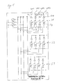
- FIG. 1 shows three connection units or stages S1, S2 and S3, each of identically constructed construction, for connecting the charging circuit to the three-phase supply network L1, L2 and L3 with neutral conductor N, the three stages S1 to S3 being connected in parallel to each other and each individual stage S1, S2 and S3 is connected to each line L1, L2, L3 and N of the supply network.
- each individual stage S1 to S3 is designed as a half-controlled rectifier bridge, wherein the connection point of a valve string or valve path VP1 to VP4 consisting of a diode D1 to D4 and a thyristor T1 to T4 to one of the lines L1, L2, L3 and N of the Supply network between the anode of the diode D1 to D4 and the cathode of the thyristor T1 to T4 is arranged.
- the same number of (four) valve trains or valve paths VP1 to VP4 corresponding to the number of (four) lines of the supply network is provided.
- the four valve trains or valve paths VP1 to VP4 are each constructed identically and connected in parallel to one another, the output signals or output voltage being output at the cathodes of the diodes D1 to D4 and the anodes of the timers T1 to T4.
- each individual stage S1, S2 and S3 can access the complete supply network L1, L2, L3 and N, wherein each individual valve train or valve path VP1 to VP4 can be selectively switched on or off by means of switching on or off of the respective thyristor T1 to T4.
- each stage S1 to S3 or each rectifier with any phase assignment fed from the utility grid can be operated as a rectifier independent of the other stages or rectifiers.
- the first stage S1 between L1 and L2, the second stage S2 between L2 and L3 and the third stage S3 be switched between L3 and L1.
- the second stage S2 between L3 and the neutral N can be switched and the third stage S3 can remain unchanged.
- a parallel connection of a plurality of semi-controlled rectifier which, however, are not completely connected to the supply voltage to provide.
- a first rectifier bridge may be selectively switched only between the supply voltage terminals L1, L2, and N.
- the rectifiers or stages may be followed by stub line compensation circuits (PFCs) which are each fed separately from the associated stages or rectifier bridges and whose output voltages may be interconnected to an intermediate circuit feeding downstream DC-to-DC converters.
- PFCs stub line compensation circuits
- a DC (DC) converter can be supplied with the DC link voltage generated by the PFCs.
- the DC link voltage is applied, for example, via capacitors connected in series, wherein the series connection of the capacitors or the capacitor bridge shown forms an input stage in which a center point or a (as stiff as possible) midpoint voltage is formed between the series-connected capacitors, each as an input one of the series-connected DC-DC converter shown below is used.
- the series-connected capacitors preferably have the same capacity.
- the upstream series-connected capacitors each supply the input voltage of the respective downstream bridge circuit.
- a bridge circuit feeds the first primary winding of the potential separation point serving as transformer, which lies together with the parasitic inductance in the bridge branch.
- the bridge branch is connected between a transistor serving as switching elements and the anode of a diode and on the opposite side between the cathode of a diode and a second switching element connected.
- the diodes are thus connected in parallel and in the same flow or blocking direction, so that the capacitor can not discharge via the diodes.
- both transistors In order to allow a current to flow through the primary-side transformer winding, both transistors must be switched on simultaneously.
- the second bridge circuit is basically identical in construction to the bridge circuit described above and is fed by the second capacitor.
- the drive signals of the first bridge circuit are in phase, and preferably shifted by 180 degrees to the drive signals of the second bridge circuit.
Landscapes
- Engineering & Computer Science (AREA)
- Power Engineering (AREA)
- Transportation (AREA)
- Mechanical Engineering (AREA)
- Rectifiers (AREA)
- Charge And Discharge Circuits For Batteries Or The Like (AREA)
Applications Claiming Priority (2)
| Application Number | Priority Date | Filing Date | Title |
|---|---|---|---|
| DE102010009343 | 2010-02-25 | ||
| DE102010010722A DE102010010722A1 (de) | 2010-02-25 | 2010-03-09 | Ladegerät für ein Elektrofahrzeug |
Publications (3)
| Publication Number | Publication Date |
|---|---|
| EP2362522A2 true EP2362522A2 (fr) | 2011-08-31 |
| EP2362522A3 EP2362522A3 (fr) | 2013-05-01 |
| EP2362522B1 EP2362522B1 (fr) | 2017-06-28 |
Family
ID=44259756
Family Applications (1)
| Application Number | Title | Priority Date | Filing Date |
|---|---|---|---|
| EP11155935.7A Not-in-force EP2362522B1 (fr) | 2010-02-25 | 2011-02-25 | Appareil de chargement pour un véhicule électrique |
Country Status (2)
| Country | Link |
|---|---|
| EP (1) | EP2362522B1 (fr) |
| DE (1) | DE102010010722A1 (fr) |
Cited By (5)
| Publication number | Priority date | Publication date | Assignee | Title |
|---|---|---|---|---|
| DE102013007971A1 (de) * | 2013-05-10 | 2014-11-27 | Audi Ag | Verfahren zum Betrieb einer Ladevorrichtung für das ein- und mehrphasige Laden eines Energiespeichers eines Kraftfahrzeugs und Ladevorrichtung |
| EP2869445A1 (fr) * | 2013-11-01 | 2015-05-06 | DET International Holding Limited | Redresseur adaptatif pour l'opération avec des réseaux CA différents |
| DE102013221501A1 (de) * | 2013-10-23 | 2015-05-07 | Dr.Ing.H.C. F. Porsche Ag | Ladegerät und Verfahren zum Betreiben eines Ladegeräts |
| CN112511145A (zh) * | 2020-12-04 | 2021-03-16 | 深圳市金威源科技股份有限公司 | 一种开关电源中待机零无功消耗控制电路 |
| WO2021047743A1 (fr) * | 2019-09-13 | 2021-03-18 | Hs-Drives Gmbh | Système comprenant au moins un redresseur |
Families Citing this family (7)
| Publication number | Priority date | Publication date | Assignee | Title |
|---|---|---|---|---|
| US9376024B2 (en) | 2013-02-06 | 2016-06-28 | GM Global Technology Operations LLC | Scalable high voltage charging and detection system for plug-in electric vehicles |
| DE102015101092A1 (de) * | 2015-01-27 | 2016-07-28 | Dr. Ing. H.C. F. Porsche Aktiengesellschaft | Ladegerät für ein Plug-In-Fahrzeug und Plug-In-Fahrzeug |
| ES2654807T3 (es) | 2015-08-20 | 2018-02-15 | Wegmann Automotive Gmbh & Co. Kg | Terminal de batería con protección antitorsión interna |
| DE102017201734B4 (de) * | 2017-02-03 | 2018-09-13 | Volkswagen Aktiengesellschaft | Ladegerät und Verfahren zur Reduzierung der Schieflast eines zweiphasigen Ladegeräts |
| DE102018203198A1 (de) * | 2018-03-02 | 2019-09-05 | Bob Patent Gmbh | Verfahren zum Laden eines elektrisch angetriebenen oder antreibbaren Kraftfahrzeugs sowie Ladestation |
| CN111376759B (zh) * | 2018-12-29 | 2022-05-13 | 比亚迪股份有限公司 | 车载充电机及车辆 |
| DE102020213002A1 (de) | 2020-10-15 | 2022-04-21 | Robert Bosch Gesellschaft mit beschränkter Haftung | Anschlussvorrichtung für eine Vorrichtung zum Aufladen eines elektrischen Energiespeichers, Ladevorrichtung und Elektrofahrzeug |
Family Cites Families (7)
| Publication number | Priority date | Publication date | Assignee | Title |
|---|---|---|---|---|
| JPS566675A (en) * | 1979-06-27 | 1981-01-23 | Toshiba Corp | Controlling system for controlled converter device |
| JPS57186985A (en) * | 1981-05-08 | 1982-11-17 | Toshiba Corp | Control power source of multiphase rectifier |
| JPH08331851A (ja) * | 1995-06-01 | 1996-12-13 | Yaskawa Electric Corp | メイン電源立ち上げ方法とその装置 |
| JPH10127065A (ja) * | 1996-10-18 | 1998-05-15 | Tokyo Electric Power Co Inc:The | 電力変換装置 |
| JP4177983B2 (ja) * | 2001-11-30 | 2008-11-05 | 株式会社日立製作所 | 多重電力変換器とその制御方法 |
| AUPS118302A0 (en) * | 2002-03-18 | 2002-04-18 | Rectifier Technologies Pacific Pty Ltd | Wide bandwidth ac-dc converter |
| DE102005042010A1 (de) * | 2005-09-02 | 2007-03-22 | Siemens Ag | Generatorvorrichtung zum voneinander unabhängigen Laden von mindestens zwei Batterien |
-
2010
- 2010-03-09 DE DE102010010722A patent/DE102010010722A1/de not_active Withdrawn
-
2011
- 2011-02-25 EP EP11155935.7A patent/EP2362522B1/fr not_active Not-in-force
Non-Patent Citations (1)
| Title |
|---|
| None |
Cited By (11)
| Publication number | Priority date | Publication date | Assignee | Title |
|---|---|---|---|---|
| DE102013007971A1 (de) * | 2013-05-10 | 2014-11-27 | Audi Ag | Verfahren zum Betrieb einer Ladevorrichtung für das ein- und mehrphasige Laden eines Energiespeichers eines Kraftfahrzeugs und Ladevorrichtung |
| US9796278B2 (en) | 2013-05-10 | 2017-10-24 | Audi Ag | Method for operating a charging device for single-phase and multi-phase charging of an energy store in a motor vehicle and charging device |
| DE102013221501A1 (de) * | 2013-10-23 | 2015-05-07 | Dr.Ing.H.C. F. Porsche Ag | Ladegerät und Verfahren zum Betreiben eines Ladegeräts |
| DE102013221501B4 (de) * | 2013-10-23 | 2025-06-26 | Dr.Ing.H.C. F. Porsche Ag | Ladegerät und Verfahren zum Betreiben eines Ladegeräts |
| EP2869445A1 (fr) * | 2013-11-01 | 2015-05-06 | DET International Holding Limited | Redresseur adaptatif pour l'opération avec des réseaux CA différents |
| US20150123612A1 (en) * | 2013-11-01 | 2015-05-07 | Det International Holding Limited | Adaptable input phase switching |
| CN104796012A (zh) * | 2013-11-01 | 2015-07-22 | Det国际控股有限公司 | 可适应输入相切换 |
| US9935561B2 (en) | 2013-11-01 | 2018-04-03 | Det International Holding Limited | Adaptable input phase switching |
| CN104796012B (zh) * | 2013-11-01 | 2019-09-17 | 泰达电子股份有限公司 | 可适应输入相切换 |
| WO2021047743A1 (fr) * | 2019-09-13 | 2021-03-18 | Hs-Drives Gmbh | Système comprenant au moins un redresseur |
| CN112511145A (zh) * | 2020-12-04 | 2021-03-16 | 深圳市金威源科技股份有限公司 | 一种开关电源中待机零无功消耗控制电路 |
Also Published As
| Publication number | Publication date |
|---|---|
| DE102010010722A1 (de) | 2011-08-25 |
| EP2362522B1 (fr) | 2017-06-28 |
| EP2362522A3 (fr) | 2013-05-01 |
Similar Documents
| Publication | Publication Date | Title |
|---|---|---|
| EP2362522B1 (fr) | Appareil de chargement pour un véhicule électrique | |
| EP3333005B1 (fr) | Électronique de puissance modulaire permettant le chargement d'un véhicule électrique | |
| EP4087087A2 (fr) | Système d'alimentation électrique | |
| DE102013212682B4 (de) | Energiespeichereinrichtung mit Gleichspannungsversorgungsschaltung und Verfahren zum Bereitstellen einer Gleichspannung aus einer Energiespeichereinrichtung | |
| DE102009028973A1 (de) | DC/DC-Wandlerschaltung und Batteriesystem | |
| DE112016004548T5 (de) | Leistungsmanagement unter Verwenden einer synchronen gemeinsamen Kopplung | |
| DE102011075927A1 (de) | Multifunktionaler stromrichter von gleichspannung zu gleichspannung, von gleichspannung zu wechselspannung und von wechselspannung zu gleichspannung | |
| DE102018006810A1 (de) | Energiewandler zum energietechnischen Koppeln eines Gleichspannungsbordnetzes mit einer Wechselspannungs- oder einer Gleichspannungsenergiequelle | |
| DE102011003859A1 (de) | System zum Laden eines Energiespeichers und Verfahren zum Betrieb des Ladesystems | |
| DE102010041040A1 (de) | Energieversorgungsnetz und Verfahren zum Laden mindestens einer als Energiespeicher für einen Gleichspannungszwischenkreis dienenden Energiespeicherzelle in einem Energieversorgungsnetz | |
| DE102013212716A1 (de) | Energiespeichereinrichtung mit Gleichspannungsversorgungsschaltung und Verfahren zum Bereitstellen einer Gleichspannung aus einer Energiespeichereinrichtung | |
| DE102018221519B4 (de) | Fahrzeugseitige Ladevorrichtung | |
| DE102011003861A1 (de) | System zum Laden eines Energiespeichers und Verfahren zum Betrieb eines Ladesystems | |
| EP2609676B1 (fr) | Convertisseur de traction | |
| DE102018008603A1 (de) | Schaltungsanordnung und Verfahren zum Laden einer Batterieanordnung mit mehreren Batteriemodulen | |
| DE102019106485A1 (de) | Weissach-Gleichrichteranordnung | |
| DE4426017C2 (de) | Stromversorgungsgerät, insbesondere Batterie-Ladegerät für Elektrofahrzeuge oder dergleichen | |
| EP2845303B1 (fr) | Convertisseur et procédés de conversion de tension | |
| DE102012220371A1 (de) | Vorrichtung zum Laden eines elektrischen Energiespeichers aus einer Wechselspannungsquelle | |
| DE102009028974A1 (de) | Halbbrücken-Konverter für ein Batteriesystem und Batteriesystem | |
| EP3913786A1 (fr) | Dispositif de conversion avec un convertisseur commuté par la ligne ainsi que procédé de démarrage du convertisseur | |
| DE102022210390A1 (de) | Ladegerät und Verfahren zum Betrieb des Ladegerätes | |
| DE102013105098A1 (de) | Integrierter Solar-/Batteriewechselrichter | |
| WO2020064429A1 (fr) | Circuit de charge destiné à un accumulateur d'énergie électrique embarqué dans un véhicule | |
| DE102012206801A1 (de) | Schaltung mit einer stromrichterschaltung und verfahren zur leistungsanpassung |
Legal Events
| Date | Code | Title | Description |
|---|---|---|---|
| PUAI | Public reference made under article 153(3) epc to a published international application that has entered the european phase |
Free format text: ORIGINAL CODE: 0009012 |
|
| AK | Designated contracting states |
Kind code of ref document: A2 Designated state(s): AL AT BE BG CH CY CZ DE DK EE ES FI FR GB GR HR HU IE IS IT LI LT LU LV MC MK MT NL NO PL PT RO RS SE SI SK SM TR |
|
| AX | Request for extension of the european patent |
Extension state: BA ME |
|
| PUAL | Search report despatched |
Free format text: ORIGINAL CODE: 0009013 |
|
| AK | Designated contracting states |
Kind code of ref document: A3 Designated state(s): AL AT BE BG CH CY CZ DE DK EE ES FI FR GB GR HR HU IE IS IT LI LT LU LV MC MK MT NL NO PL PT RO RS SE SI SK SM TR |
|
| AX | Request for extension of the european patent |
Extension state: BA ME |
|
| RIC1 | Information provided on ipc code assigned before grant |
Ipc: H02H 3/253 20060101ALI20130326BHEP Ipc: H02M 1/42 20070101ALI20130326BHEP Ipc: H02M 7/162 20060101ALI20130326BHEP Ipc: H02M 1/084 20060101ALI20130326BHEP Ipc: H02J 7/02 20060101AFI20130326BHEP Ipc: G05F 1/565 20060101ALI20130326BHEP |
|
| 17P | Request for examination filed |
Effective date: 20131030 |
|
| RBV | Designated contracting states (corrected) |
Designated state(s): AL AT BE BG CH CY CZ DE DK EE ES FI FR GB GR HR HU IE IS IT LI LT LU LV MC MK MT NL NO PL PT RO RS SE SI SK SM TR |
|
| 17Q | First examination report despatched |
Effective date: 20161021 |
|
| REG | Reference to a national code |
Ref country code: DE Ref legal event code: R079 Ref document number: 502011012507 Country of ref document: DE Free format text: PREVIOUS MAIN CLASS: H02J0007020000 Ipc: B60L0011180000 |
|
| RAP1 | Party data changed (applicant data changed or rights of an application transferred) |
Owner name: EDAG ENGINEERING GMBH |
|
| GRAJ | Information related to disapproval of communication of intention to grant by the applicant or resumption of examination proceedings by the epo deleted |
Free format text: ORIGINAL CODE: EPIDOSDIGR1 |
|
| RIC1 | Information provided on ipc code assigned before grant |
Ipc: H02M 7/25 20060101ALI20170131BHEP Ipc: H02J 7/02 20160101ALI20170131BHEP Ipc: B60L 11/18 20060101AFI20170131BHEP Ipc: H02M 7/23 20060101ALI20170131BHEP Ipc: H02M 7/19 20060101ALI20170131BHEP Ipc: H02M 7/17 20060101ALI20170131BHEP Ipc: H02M 7/155 20060101ALI20170131BHEP Ipc: H02M 7/217 20060101ALI20170131BHEP Ipc: H02M 1/084 20060101ALI20170131BHEP |
|
| GRAP | Despatch of communication of intention to grant a patent |
Free format text: ORIGINAL CODE: EPIDOSNIGR1 |
|
| INTG | Intention to grant announced |
Effective date: 20170310 |
|
| GRAS | Grant fee paid |
Free format text: ORIGINAL CODE: EPIDOSNIGR3 |
|
| GRAA | (expected) grant |
Free format text: ORIGINAL CODE: 0009210 |
|
| AK | Designated contracting states |
Kind code of ref document: B1 Designated state(s): AL AT BE BG CH CY CZ DE DK EE ES FI FR GB GR HR HU IE IS IT LI LT LU LV MC MK MT NL NO PL PT RO RS SE SI SK SM TR |
|
| REG | Reference to a national code |
Ref country code: GB Ref legal event code: FG4D Free format text: NOT ENGLISH |
|
| REG | Reference to a national code |
Ref country code: CH Ref legal event code: EP |
|
| REG | Reference to a national code |
Ref country code: AT Ref legal event code: REF Ref document number: 904534 Country of ref document: AT Kind code of ref document: T Effective date: 20170715 |
|
| REG | Reference to a national code |
Ref country code: IE Ref legal event code: FG4D Free format text: LANGUAGE OF EP DOCUMENT: GERMAN |
|
| REG | Reference to a national code |
Ref country code: DE Ref legal event code: R096 Ref document number: 502011012507 Country of ref document: DE |
|
| PG25 | Lapsed in a contracting state [announced via postgrant information from national office to epo] |
Ref country code: GR Free format text: LAPSE BECAUSE OF FAILURE TO SUBMIT A TRANSLATION OF THE DESCRIPTION OR TO PAY THE FEE WITHIN THE PRESCRIBED TIME-LIMIT Effective date: 20170929 Ref country code: FI Free format text: LAPSE BECAUSE OF FAILURE TO SUBMIT A TRANSLATION OF THE DESCRIPTION OR TO PAY THE FEE WITHIN THE PRESCRIBED TIME-LIMIT Effective date: 20170628 Ref country code: LT Free format text: LAPSE BECAUSE OF FAILURE TO SUBMIT A TRANSLATION OF THE DESCRIPTION OR TO PAY THE FEE WITHIN THE PRESCRIBED TIME-LIMIT Effective date: 20170628 Ref country code: HR Free format text: LAPSE BECAUSE OF FAILURE TO SUBMIT A TRANSLATION OF THE DESCRIPTION OR TO PAY THE FEE WITHIN THE PRESCRIBED TIME-LIMIT Effective date: 20170628 Ref country code: NO Free format text: LAPSE BECAUSE OF FAILURE TO SUBMIT A TRANSLATION OF THE DESCRIPTION OR TO PAY THE FEE WITHIN THE PRESCRIBED TIME-LIMIT Effective date: 20170928 |
|
| REG | Reference to a national code |
Ref country code: NL Ref legal event code: MP Effective date: 20170628 |
|
| REG | Reference to a national code |
Ref country code: LT Ref legal event code: MG4D |
|
| PG25 | Lapsed in a contracting state [announced via postgrant information from national office to epo] |
Ref country code: SE Free format text: LAPSE BECAUSE OF FAILURE TO SUBMIT A TRANSLATION OF THE DESCRIPTION OR TO PAY THE FEE WITHIN THE PRESCRIBED TIME-LIMIT Effective date: 20170628 Ref country code: NL Free format text: LAPSE BECAUSE OF FAILURE TO SUBMIT A TRANSLATION OF THE DESCRIPTION OR TO PAY THE FEE WITHIN THE PRESCRIBED TIME-LIMIT Effective date: 20170628 Ref country code: BG Free format text: LAPSE BECAUSE OF FAILURE TO SUBMIT A TRANSLATION OF THE DESCRIPTION OR TO PAY THE FEE WITHIN THE PRESCRIBED TIME-LIMIT Effective date: 20170928 Ref country code: RS Free format text: LAPSE BECAUSE OF FAILURE TO SUBMIT A TRANSLATION OF THE DESCRIPTION OR TO PAY THE FEE WITHIN THE PRESCRIBED TIME-LIMIT Effective date: 20170628 Ref country code: LV Free format text: LAPSE BECAUSE OF FAILURE TO SUBMIT A TRANSLATION OF THE DESCRIPTION OR TO PAY THE FEE WITHIN THE PRESCRIBED TIME-LIMIT Effective date: 20170628 |
|
| PG25 | Lapsed in a contracting state [announced via postgrant information from national office to epo] |
Ref country code: RO Free format text: LAPSE BECAUSE OF FAILURE TO SUBMIT A TRANSLATION OF THE DESCRIPTION OR TO PAY THE FEE WITHIN THE PRESCRIBED TIME-LIMIT Effective date: 20170628 Ref country code: EE Free format text: LAPSE BECAUSE OF FAILURE TO SUBMIT A TRANSLATION OF THE DESCRIPTION OR TO PAY THE FEE WITHIN THE PRESCRIBED TIME-LIMIT Effective date: 20170628 Ref country code: CZ Free format text: LAPSE BECAUSE OF FAILURE TO SUBMIT A TRANSLATION OF THE DESCRIPTION OR TO PAY THE FEE WITHIN THE PRESCRIBED TIME-LIMIT Effective date: 20170628 Ref country code: SK Free format text: LAPSE BECAUSE OF FAILURE TO SUBMIT A TRANSLATION OF THE DESCRIPTION OR TO PAY THE FEE WITHIN THE PRESCRIBED TIME-LIMIT Effective date: 20170628 |
|
| REG | Reference to a national code |
Ref country code: FR Ref legal event code: PLFP Year of fee payment: 8 |
|
| PG25 | Lapsed in a contracting state [announced via postgrant information from national office to epo] |
Ref country code: ES Free format text: LAPSE BECAUSE OF FAILURE TO SUBMIT A TRANSLATION OF THE DESCRIPTION OR TO PAY THE FEE WITHIN THE PRESCRIBED TIME-LIMIT Effective date: 20170628 Ref country code: SM Free format text: LAPSE BECAUSE OF FAILURE TO SUBMIT A TRANSLATION OF THE DESCRIPTION OR TO PAY THE FEE WITHIN THE PRESCRIBED TIME-LIMIT Effective date: 20170628 Ref country code: IS Free format text: LAPSE BECAUSE OF FAILURE TO SUBMIT A TRANSLATION OF THE DESCRIPTION OR TO PAY THE FEE WITHIN THE PRESCRIBED TIME-LIMIT Effective date: 20171028 Ref country code: IT Free format text: LAPSE BECAUSE OF FAILURE TO SUBMIT A TRANSLATION OF THE DESCRIPTION OR TO PAY THE FEE WITHIN THE PRESCRIBED TIME-LIMIT Effective date: 20170628 Ref country code: PL Free format text: LAPSE BECAUSE OF FAILURE TO SUBMIT A TRANSLATION OF THE DESCRIPTION OR TO PAY THE FEE WITHIN THE PRESCRIBED TIME-LIMIT Effective date: 20170628 |
|
| REG | Reference to a national code |
Ref country code: DE Ref legal event code: R097 Ref document number: 502011012507 Country of ref document: DE |
|
| PG25 | Lapsed in a contracting state [announced via postgrant information from national office to epo] |
Ref country code: DK Free format text: LAPSE BECAUSE OF FAILURE TO SUBMIT A TRANSLATION OF THE DESCRIPTION OR TO PAY THE FEE WITHIN THE PRESCRIBED TIME-LIMIT Effective date: 20170628 |
|
| PLBE | No opposition filed within time limit |
Free format text: ORIGINAL CODE: 0009261 |
|
| STAA | Information on the status of an ep patent application or granted ep patent |
Free format text: STATUS: NO OPPOSITION FILED WITHIN TIME LIMIT |
|
| 26N | No opposition filed |
Effective date: 20180329 |
|
| PGFP | Annual fee paid to national office [announced via postgrant information from national office to epo] |
Ref country code: DE Payment date: 20180430 Year of fee payment: 8 |
|
| PG25 | Lapsed in a contracting state [announced via postgrant information from national office to epo] |
Ref country code: SI Free format text: LAPSE BECAUSE OF FAILURE TO SUBMIT A TRANSLATION OF THE DESCRIPTION OR TO PAY THE FEE WITHIN THE PRESCRIBED TIME-LIMIT Effective date: 20170628 |
|
| REG | Reference to a national code |
Ref country code: CH Ref legal event code: PL |
|
| PG25 | Lapsed in a contracting state [announced via postgrant information from national office to epo] |
Ref country code: MT Free format text: LAPSE BECAUSE OF FAILURE TO SUBMIT A TRANSLATION OF THE DESCRIPTION OR TO PAY THE FEE WITHIN THE PRESCRIBED TIME-LIMIT Effective date: 20170628 Ref country code: MC Free format text: LAPSE BECAUSE OF FAILURE TO SUBMIT A TRANSLATION OF THE DESCRIPTION OR TO PAY THE FEE WITHIN THE PRESCRIBED TIME-LIMIT Effective date: 20170628 |
|
| REG | Reference to a national code |
Ref country code: IE Ref legal event code: MM4A |
|
| REG | Reference to a national code |
Ref country code: BE Ref legal event code: MM Effective date: 20180228 |
|
| PG25 | Lapsed in a contracting state [announced via postgrant information from national office to epo] |
Ref country code: CH Free format text: LAPSE BECAUSE OF NON-PAYMENT OF DUE FEES Effective date: 20180228 Ref country code: LI Free format text: LAPSE BECAUSE OF NON-PAYMENT OF DUE FEES Effective date: 20180228 Ref country code: LU Free format text: LAPSE BECAUSE OF NON-PAYMENT OF DUE FEES Effective date: 20180225 |
|
| REG | Reference to a national code |
Ref country code: DE Ref legal event code: R079 Ref document number: 502011012507 Country of ref document: DE Free format text: PREVIOUS MAIN CLASS: B60L0011180000 Ipc: B60L0050500000 |
|
| PG25 | Lapsed in a contracting state [announced via postgrant information from national office to epo] |
Ref country code: IE Free format text: LAPSE BECAUSE OF NON-PAYMENT OF DUE FEES Effective date: 20180225 |
|
| PG25 | Lapsed in a contracting state [announced via postgrant information from national office to epo] |
Ref country code: BE Free format text: LAPSE BECAUSE OF NON-PAYMENT OF DUE FEES Effective date: 20180228 |
|
| REG | Reference to a national code |
Ref country code: AT Ref legal event code: MM01 Ref document number: 904534 Country of ref document: AT Kind code of ref document: T Effective date: 20180225 |
|
| PG25 | Lapsed in a contracting state [announced via postgrant information from national office to epo] |
Ref country code: AT Free format text: LAPSE BECAUSE OF NON-PAYMENT OF DUE FEES Effective date: 20180225 |
|
| PGFP | Annual fee paid to national office [announced via postgrant information from national office to epo] |
Ref country code: GB Payment date: 20190227 Year of fee payment: 9 |
|
| PGFP | Annual fee paid to national office [announced via postgrant information from national office to epo] |
Ref country code: FR Payment date: 20190226 Year of fee payment: 9 |
|
| REG | Reference to a national code |
Ref country code: DE Ref legal event code: R119 Ref document number: 502011012507 Country of ref document: DE |
|
| PG25 | Lapsed in a contracting state [announced via postgrant information from national office to epo] |
Ref country code: DE Free format text: LAPSE BECAUSE OF NON-PAYMENT OF DUE FEES Effective date: 20190903 |
|
| PG25 | Lapsed in a contracting state [announced via postgrant information from national office to epo] |
Ref country code: TR Free format text: LAPSE BECAUSE OF FAILURE TO SUBMIT A TRANSLATION OF THE DESCRIPTION OR TO PAY THE FEE WITHIN THE PRESCRIBED TIME-LIMIT Effective date: 20170628 |
|
| PG25 | Lapsed in a contracting state [announced via postgrant information from national office to epo] |
Ref country code: HU Free format text: LAPSE BECAUSE OF FAILURE TO SUBMIT A TRANSLATION OF THE DESCRIPTION OR TO PAY THE FEE WITHIN THE PRESCRIBED TIME-LIMIT; INVALID AB INITIO Effective date: 20110225 Ref country code: PT Free format text: LAPSE BECAUSE OF FAILURE TO SUBMIT A TRANSLATION OF THE DESCRIPTION OR TO PAY THE FEE WITHIN THE PRESCRIBED TIME-LIMIT Effective date: 20170628 |
|
| PG25 | Lapsed in a contracting state [announced via postgrant information from national office to epo] |
Ref country code: CY Free format text: LAPSE BECAUSE OF FAILURE TO SUBMIT A TRANSLATION OF THE DESCRIPTION OR TO PAY THE FEE WITHIN THE PRESCRIBED TIME-LIMIT Effective date: 20170628 Ref country code: MK Free format text: LAPSE BECAUSE OF NON-PAYMENT OF DUE FEES Effective date: 20170628 |
|
| PG25 | Lapsed in a contracting state [announced via postgrant information from national office to epo] |
Ref country code: AL Free format text: LAPSE BECAUSE OF FAILURE TO SUBMIT A TRANSLATION OF THE DESCRIPTION OR TO PAY THE FEE WITHIN THE PRESCRIBED TIME-LIMIT Effective date: 20170628 |
|
| GBPC | Gb: european patent ceased through non-payment of renewal fee |
Effective date: 20200225 |
|
| PG25 | Lapsed in a contracting state [announced via postgrant information from national office to epo] |
Ref country code: FR Free format text: LAPSE BECAUSE OF NON-PAYMENT OF DUE FEES Effective date: 20200229 Ref country code: GB Free format text: LAPSE BECAUSE OF NON-PAYMENT OF DUE FEES Effective date: 20200225 |