EP2362712A2 - LED-Beleuchtungsschaltung - Google Patents
LED-Beleuchtungsschaltung Download PDFInfo
- Publication number
- EP2362712A2 EP2362712A2 EP11153894A EP11153894A EP2362712A2 EP 2362712 A2 EP2362712 A2 EP 2362712A2 EP 11153894 A EP11153894 A EP 11153894A EP 11153894 A EP11153894 A EP 11153894A EP 2362712 A2 EP2362712 A2 EP 2362712A2
- Authority
- EP
- European Patent Office
- Prior art keywords
- voltage
- light source
- led
- led light
- capacitor
- Prior art date
- Legal status (The legal status is an assumption and is not a legal conclusion. Google has not performed a legal analysis and makes no representation as to the accuracy of the status listed.)
- Ceased
Links
- 239000003990 capacitor Substances 0.000 claims description 49
- 238000010586 diagram Methods 0.000 description 4
- 230000015556 catabolic process Effects 0.000 description 2
- 230000000694 effects Effects 0.000 description 2
- 102000004129 N-Type Calcium Channels Human genes 0.000 description 1
- 108090000699 N-Type Calcium Channels Proteins 0.000 description 1
- 238000007796 conventional method Methods 0.000 description 1
Images

Classifications
-
- H—ELECTRICITY
- H05—ELECTRIC TECHNIQUES NOT OTHERWISE PROVIDED FOR
- H05B—ELECTRIC HEATING; ELECTRIC LIGHT SOURCES NOT OTHERWISE PROVIDED FOR; CIRCUIT ARRANGEMENTS FOR ELECTRIC LIGHT SOURCES, IN GENERAL
- H05B45/00—Circuit arrangements for operating light-emitting diodes [LED]
- H05B45/50—Circuit arrangements for operating light-emitting diodes [LED] responsive to malfunctions or undesirable behaviour of LEDs; responsive to LED life; Protective circuits
-
- H—ELECTRICITY
- H05—ELECTRIC TECHNIQUES NOT OTHERWISE PROVIDED FOR
- H05B—ELECTRIC HEATING; ELECTRIC LIGHT SOURCES NOT OTHERWISE PROVIDED FOR; CIRCUIT ARRANGEMENTS FOR ELECTRIC LIGHT SOURCES, IN GENERAL
- H05B45/00—Circuit arrangements for operating light-emitting diodes [LED]
- H05B45/30—Driver circuits
- H05B45/37—Converter circuits
- H05B45/3725—Switched mode power supply [SMPS]
-
- H—ELECTRICITY
- H05—ELECTRIC TECHNIQUES NOT OTHERWISE PROVIDED FOR
- H05B—ELECTRIC HEATING; ELECTRIC LIGHT SOURCES NOT OTHERWISE PROVIDED FOR; CIRCUIT ARRANGEMENTS FOR ELECTRIC LIGHT SOURCES, IN GENERAL
- H05B45/00—Circuit arrangements for operating light-emitting diodes [LED]
- H05B45/30—Driver circuits
- H05B45/37—Converter circuits
- H05B45/3725—Switched mode power supply [SMPS]
- H05B45/375—Switched mode power supply [SMPS] using buck topology
-
- H—ELECTRICITY
- H05—ELECTRIC TECHNIQUES NOT OTHERWISE PROVIDED FOR
- H05B—ELECTRIC HEATING; ELECTRIC LIGHT SOURCES NOT OTHERWISE PROVIDED FOR; CIRCUIT ARRANGEMENTS FOR ELECTRIC LIGHT SOURCES, IN GENERAL
- H05B45/00—Circuit arrangements for operating light-emitting diodes [LED]
- H05B45/30—Driver circuits
- H05B45/37—Converter circuits
- H05B45/3725—Switched mode power supply [SMPS]
- H05B45/38—Switched mode power supply [SMPS] using boost topology
-
- Y—GENERAL TAGGING OF NEW TECHNOLOGICAL DEVELOPMENTS; GENERAL TAGGING OF CROSS-SECTIONAL TECHNOLOGIES SPANNING OVER SEVERAL SECTIONS OF THE IPC; TECHNICAL SUBJECTS COVERED BY FORMER USPC CROSS-REFERENCE ART COLLECTIONS [XRACs] AND DIGESTS
- Y02—TECHNOLOGIES OR APPLICATIONS FOR MITIGATION OR ADAPTATION AGAINST CLIMATE CHANGE
- Y02B—CLIMATE CHANGE MITIGATION TECHNOLOGIES RELATED TO BUILDINGS, e.g. HOUSING, HOUSE APPLIANCES OR RELATED END-USER APPLICATIONS
- Y02B20/00—Energy efficient lighting technologies, e.g. halogen lamps or gas discharge lamps
- Y02B20/30—Semiconductor lamps, e.g. solid state lamps [SSL] light emitting diodes [LED] or organic LED [OLED]
Definitions
- the present invention relates to a LED lighting circuit.
- a LED lighting circuit for lighting a LED light source formed by light-emitting diodes is provided.
- a LED lighting circuit of Conventional Example 1 is formed by an AC power source AC, a diode bridge DB, a DC/DC converter 1, an LED light source part 2, and a control part 3.
- a circuit diagram of Conventional Example 1 is shown in Fig. 2 .
- the AC power source AC is a commercial power source.
- the AC power source AC outputs an AC voltage V1 of 100 V to the diode bridge DB.
- the diode bridge DB is formed by a full-wave rectifying circuit, and a capacitor C1 formed by an electrolytic capacitor is connected between output ends.
- the diode bridge DB smoothes the AC voltage V1 so as to generate a DC voltage V2a of substantially 140 V in both ends of the capacitor C1.
- the DC/DC converter 1 forms a step-down chopper circuit with a diode D1, a capacitor C2, an inductor L1, and a switching element Q1.
- the capacitor C2 is formed by an electrolytic capacitor
- the switching element Q1 is formed by an n-type channel MOSFET.
- a series circuit of the capacitor C2, the inductor L1, the switching element Q1, and a resistance R1 is connected in parallel to the capacitor C1.
- a positive electrode is connected to a positive electrode of the capacitor C1
- a negative electrode is connected to the inductor L1.
- a drain terminal is connected to the inductor L1
- a gate terminal is connected to the control part 3
- a source terminal is connected to a negative electrode of the capacitor C1 via a resistance R1.
- the diode D1 is connected in parallel to the capacitor C2 and the inductor L1.
- an anode is connected to a connection point between the inductor L1 and the switching element Q1, and a cathode is connected to the positive electrode of the capacitor C2.
- the DC/DC converter 1 forms the step-down chopper circuit with the above configuration.
- the switching element Q1 is turned ON/OFF by the control part 3, so that the AC voltage V2a is converted to generate a DC voltage V3 in both ends of the capacitor C2.
- the LED light source part 2 is configured by a plurality of light-emitting diodes, and connected in parallel to the capacitor C2. An LED current flows by the DC voltage V3 generated in the both ends of the capacitor C2 to light the LED light source part 2.
- the control part 3 has a DC power source E as an input power source, and controls turning ON/OFF of the switching element Q1 of the DC/DC converter 1 so that a predetermined LED current flows through the LED light source part 2.
- the control part 3 detects a current flowing through the switching element Q1 by detecting a voltage in both ends of the resistance R1.
- the control part 3 also detects a current flowing through the inductor L1. When the current flowing through the switching element Q1 becomes more than a predetermined value, the control part 3 turns OFF the switching element Q1. When the current flowing through the inductor L1 becomes less than a predetermined value, the control part 3 turns ON the switching element Q1 . Thereby, the control part 3 controls the current flowing through the LED light source part 2 to be substantially constant.
- Patent Literature 1 an LED lighting circuit in which a control part is not started up in an unloaded state that light-emitting diodes are removed is provided (for example, Patent Literature 1).
- the present invention is achieved in consideration with the above situation, and an object thereof is to provide an LED lighting circuit for preventing an increase in output voltage of a DC/DC converter in an unloaded state even at the time of lighting light-emitting diodes.
- a LED lighting circuit includes a DC power source for outputting a first DC voltage, a DC/DC converter having a switching element and a capacitor for converting the first DC voltage upon turning ON/OFF of the switching element so as to generate a second DC voltage in both ends of the capacitor, an LED light source part configured by one or more light-emitting diodes, the LED light source part to be lit by flowing a LED current by the second DC voltage, a control part for controlling turning ON/OFF of the switching element so that the LED current supplied from the DC/DC converter to the LED light source part is constant, and a power supply part for supplying a drive power source for driving the control part, wherein the power supply part and the LED light source part are connected in series, the LED light source part is connected to a high voltage line side of the DC power source, the power supply part is connected to a low voltage line side of the DC power source, and at least at the time of lighting, the power supply part is supplied with a power source
- control part is configured by an integrated circuit.
- the DC power source is configured by a step-up chopper circuit.
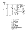
- FIG. 1 A schematic circuit configuration diagram of the embodiment of the present invention is shown in Fig. 1 .
- the present embodiment includes an AC power source AC, a diode bridge DB, a DC/DC converter 1, an LED light source part 2, a control part 3, a power factor correction circuit PFC, and a power supply part 4. It should be noted that the same configuration as Conventional Example 1 will be given the same reference numerals and description thereof will be omitted.
- a power factor correction circuit PFC (a DC power source) is connected in a subsequent stage of the diode bridge DB.
- the power factor correction circuit PFC is configured by a step-up chopper circuit, for stepping up a rectified voltage from the diode bridge DB to a desired DC voltage, so that the DC voltage is smoothed in a capacitor C1 and a DC voltage V2 (first DC voltage) is generated in both ends of the capacitor C1.
- the power factor correction circuit PFC corrects a power factor of an input current by bringing an input current close to a sinusoidal wave.
- the DC/DC converter 1 steps down the DC voltage V2 and generates a DC voltage V3 (second DC voltage) in both ends of a capacitor C2.
- the control part 3 controls turning ON/OFF of a switching element Q1 of the DC/DC converter 1 so that a predetermined LED current flows through the LED light source part 2.
- the control part 3 detects a current flowing through the switching element Q1.
- a series circuit of resistances R2 to R4 is connected in parallel to a resistance R1 connected between a source terminal of the switching element Q1 and a negative electrode of the capacitor C1.
- the control part 3 detects the current flowing through the switching element Q1 by detecting a voltage V4 generated in a connection point between the resistances R2 and R3.
- the control part 3 turns OFF the switching element Q1.
- the resistance R3 is formed by a variable resistance capable of varying the predetermined value V4a by changing a resistance value of the resistance R3.
- the control part 3 is connected to a connection point between an inductor L1 and a diode D1, and detects an inductor current flowing through the inductor L1.
- a counter electromotive voltage is generated in the inductor L1.
- a current flowing from the inductor L1 to the LED light source part 2 via the diode D1 is generated by the generated counter electromotive voltage.
- the control part 3 detects the inductor current flowing through the inductor L1, and turns ON the switching element Q1 when the inductor current becomes less than a predetermined value. With the above configuration, the control part 3 controls the LED current flowing through the LED light source part 2 to be substantially constant by repeatedly turning ON/OFF the switching Q1 .
- the power supply part 4 forms a series circuit with the LED light source part 2, and is connected in parallel to the capacitor C1.
- An anode side of the LED light source part 2 is connected to a high voltage line connected to a positive electrode of the capacitor C1, and one end of the power supply part 4 is connected to a low voltage line connected to a negative electrode of the capacitor C1.
- the power supply part 4 is configured by connecting a resistance R5 and a capacitor C3 formed by an electrolytic capacitor in series.
- One end of the resistance R5 is connected to a cathode side of the LED light source part 2, the other end of the resistance R5 is connected to a positive electrode of the capacitor C3, and a negative electrode of the capacitor C3 is connected to a negative electrode of the capacitor C1.
- the capacitor C3 is electrically charged by the DC voltage V2 outputted by the power factor correction circuit PFC via the LED light source part 2 and the resistance R5, so that a DC voltage V5 is generated in both ends of the capacitor C3.
- the control part 3 is connected in parallel to the capacitor C3, and the DC voltage V5 generated in the both ends of the capacitor C3 serves as a drive power source of the control part 3.
- the DC/DC converter 1 of the present embodiment forms a step-down chopper circuit
- the DC/DC converter may be formed by a half bridge circuit or a step-up/down chopper circuit.
- the control part 3 may be configured by an integral circuit in which the switching element Q1 and the resistances R1 to R4 are incorporated (so-called IPD (Intelligent Power Device)). Thereby, the configuration of the LED lighting circuit can be simplified.
- IPD Intelligent Power Device
Landscapes
- Circuit Arrangement For Electric Light Sources In General (AREA)
- Led Devices (AREA)
Applications Claiming Priority (1)
| Application Number | Priority Date | Filing Date | Title |
|---|---|---|---|
| JP2010036033A JP5796175B2 (ja) | 2010-02-22 | 2010-02-22 | Led点灯回路 |
Publications (2)
| Publication Number | Publication Date |
|---|---|
| EP2362712A2 true EP2362712A2 (de) | 2011-08-31 |
| EP2362712A3 EP2362712A3 (de) | 2017-01-11 |
Family
ID=44148746
Family Applications (1)
| Application Number | Title | Priority Date | Filing Date |
|---|---|---|---|
| EP11153894.8A Ceased EP2362712A3 (de) | 2010-02-22 | 2011-02-09 | LED-Beleuchtungsschaltung |
Country Status (3)
| Country | Link |
|---|---|
| US (1) | US8502463B2 (de) |
| EP (1) | EP2362712A3 (de) |
| JP (1) | JP5796175B2 (de) |
Families Citing this family (19)
| Publication number | Priority date | Publication date | Assignee | Title |
|---|---|---|---|---|
| JP2012157220A (ja) * | 2011-01-28 | 2012-08-16 | Sony Corp | 制御装置、制御方法および電源装置 |
| KR101956269B1 (ko) * | 2011-12-14 | 2019-03-08 | 엘지디스플레이 주식회사 | 발광 다이오드의 구동장치 및 구동방법, 및 이를 이용한 액정 표시 장치 |
| JP5447497B2 (ja) * | 2011-12-26 | 2014-03-19 | 三菱電機株式会社 | 光源点灯装置及び照明装置 |
| CN102695339B (zh) | 2012-05-22 | 2014-06-25 | 矽力杰半导体技术(杭州)有限公司 | 一种高效率、高功率因数的led驱动电路 |
| JP5942320B2 (ja) * | 2012-07-30 | 2016-06-29 | パナソニックIpマネジメント株式会社 | 電源装置 |
| US9386665B2 (en) | 2013-03-14 | 2016-07-05 | Honeywell International Inc. | System for integrated lighting control, configuration, and metric tracking from multiple locations |
| JP6206814B2 (ja) | 2014-02-28 | 2017-10-04 | パナソニックIpマネジメント株式会社 | 点灯装置および該点灯装置を用いた照明システム |
| US9591706B2 (en) | 2014-05-16 | 2017-03-07 | Enertron, Inc. | Universal voltage LED power supply with regenerating power source circuitry, non-isolated load, and 0-10V dimming circuit |
| US9474113B2 (en) | 2014-05-16 | 2016-10-18 | Enerton, Inc. | Dimmable universal voltage LED power supply with regenerating power source circuitry and non-isolated load |
| JP6410182B2 (ja) * | 2015-03-03 | 2018-10-24 | パナソニックIpマネジメント株式会社 | Led駆動装置、照明装置及び照明器具 |
| JP6587054B2 (ja) * | 2015-06-19 | 2019-10-09 | パナソニックIpマネジメント株式会社 | 点灯装置及び照明器具 |
| KR102456426B1 (ko) * | 2015-12-28 | 2022-10-20 | 엘지이노텍 주식회사 | Led 전압 구동 회로 |
| US9900943B2 (en) | 2016-05-23 | 2018-02-20 | On-Bright Electronics (Shanghai) Co., Ltd. | Two-terminal integrated circuits with time-varying voltage-current characteristics including phased-locked power supplies |
| CN105979626B (zh) * | 2016-05-23 | 2018-08-24 | 昂宝电子(上海)有限公司 | 包括锁相电源的具有时变电压电流特性的双端子集成电路 |
| KR102471752B1 (ko) | 2017-09-21 | 2022-11-29 | 삼성전자주식회사 | 연산 증폭 회로, 그것을 포함하는 데이터 구동 회로, 및 그것들의 동작 방법 |
| CN110446293A (zh) * | 2018-05-04 | 2019-11-12 | 台达电子工业股份有限公司 | 发光元件驱动装置及其驱动方法 |
| EP4018787B1 (de) * | 2019-08-20 | 2023-10-11 | Signify Holding B.V. | Doppelendige nachgerüstete leuchtdiode, led-basierte beleuchtungsvorrichtung mit verbesserter polsicherheitsschaltung zum anschluss an eine stromquelle |
| US11418125B2 (en) | 2019-10-25 | 2022-08-16 | The Research Foundation For The State University Of New York | Three phase bidirectional AC-DC converter with bipolar voltage fed resonant stages |
| EP4595701A1 (de) * | 2022-09-27 | 2025-08-06 | Signify Holding B.V. | Smps-serienregler mit energierückführung zurück zur quelle |
Citations (2)
| Publication number | Priority date | Publication date | Assignee | Title |
|---|---|---|---|---|
| JP2008278641A (ja) | 2007-04-27 | 2008-11-13 | Toshiba Lighting & Technology Corp | 電源装置及び照明器具 |
| JP2008278640A (ja) * | 2007-04-27 | 2008-11-13 | Toshiba Lighting & Technology Corp | 電源装置及び照明器具 |
Family Cites Families (7)
| Publication number | Priority date | Publication date | Assignee | Title |
|---|---|---|---|---|
| JP2001215913A (ja) * | 2000-02-04 | 2001-08-10 | Toko Inc | 点灯回路 |
| JP4791794B2 (ja) * | 2005-10-21 | 2011-10-12 | パナソニック株式会社 | Led照明用アタッチメント |
| JP5491690B2 (ja) * | 2007-09-25 | 2014-05-14 | パナソニック株式会社 | 点灯装置、および照明器具 |
| JP5285266B2 (ja) * | 2007-11-29 | 2013-09-11 | パナソニック株式会社 | Led照明器具 |
| US7550934B1 (en) * | 2008-04-02 | 2009-06-23 | Micrel, Inc. | LED driver with fast open circuit protection, short circuit compensation, and rapid brightness control response |
| JP2009302017A (ja) * | 2008-06-17 | 2009-12-24 | Toshiba Lighting & Technology Corp | 発光ダイオード点灯装置および照明装置 |
| JP2010040878A (ja) * | 2008-08-06 | 2010-02-18 | Toshiba Lighting & Technology Corp | 発光ダイオード点灯装置 |
-
2010
- 2010-02-22 JP JP2010036033A patent/JP5796175B2/ja not_active Expired - Fee Related
-
2011
- 2011-02-09 EP EP11153894.8A patent/EP2362712A3/de not_active Ceased
- 2011-02-22 US US13/031,836 patent/US8502463B2/en not_active Expired - Fee Related
Patent Citations (2)
| Publication number | Priority date | Publication date | Assignee | Title |
|---|---|---|---|---|
| JP2008278641A (ja) | 2007-04-27 | 2008-11-13 | Toshiba Lighting & Technology Corp | 電源装置及び照明器具 |
| JP2008278640A (ja) * | 2007-04-27 | 2008-11-13 | Toshiba Lighting & Technology Corp | 電源装置及び照明器具 |
Also Published As
| Publication number | Publication date |
|---|---|
| JP5796175B2 (ja) | 2015-10-21 |
| US8502463B2 (en) | 2013-08-06 |
| JP2011171230A (ja) | 2011-09-01 |
| US20110204823A1 (en) | 2011-08-25 |
| EP2362712A3 (de) | 2017-01-11 |
Similar Documents
| Publication | Publication Date | Title |
|---|---|---|
| EP2362712A2 (de) | LED-Beleuchtungsschaltung | |
| US9788370B2 (en) | Light-emitting-diode-driving device, lighting apparatus for vehicle and vehicle including the same | |
| KR100716859B1 (ko) | 발광 다이오드 구동용 반도체 회로, 및 그것을 구비한 발광다이오드 구동 장치 | |
| CN102164439B (zh) | Led点灯电路 | |
| KR101302993B1 (ko) | 엘이디 구동장치 및 엘이디 조명장치 | |
| CN102549647B (zh) | 能够控制恒定发光二极管的电流的发光二极管驱动电路 | |
| US20120262068A1 (en) | Led driving circuit | |
| US20080291709A1 (en) | Switching power supply apparatus | |
| US8836297B2 (en) | Switching device and method of controlling switching device | |
| CN104272476A (zh) | 发光二极管驱动装置以及半导体装置 | |
| CN203072226U (zh) | 动态线性控制led驱动电路 | |
| JP5592667B2 (ja) | Led点灯回路 | |
| EP3139483A1 (de) | Elektronischer abwärtssperrwandler und zugehöriges verfahren zum betrieb eines elektronischen abwärtssperrwandlers | |
| JP2009189158A (ja) | 電源装置の制御方法と電源装置 | |
| US9516714B2 (en) | LED lighting device | |
| JP2011155748A (ja) | 電源装置及び照明器具 | |
| JP5848148B2 (ja) | Led電源、これを含む照明器具 | |
| CN106961761B (zh) | 直流供电装置和使用该直流供电装置的照明系统 | |
| JP6527741B2 (ja) | Led点灯装置 | |
| US20110181266A1 (en) | Switching power supply circuit | |
| JP2016170894A (ja) | 点灯装置、照明器具 | |
| JP5447497B2 (ja) | 光源点灯装置及び照明装置 | |
| WO2013024811A1 (ja) | 電源装置及び照明装置 | |
| JP2017084711A (ja) | 点灯装置および照明器具 | |
| JP6357790B2 (ja) | 点灯装置および照明器具 |
Legal Events
| Date | Code | Title | Description |
|---|---|---|---|
| PUAI | Public reference made under article 153(3) epc to a published international application that has entered the european phase |
Free format text: ORIGINAL CODE: 0009012 |
|
| AK | Designated contracting states |
Kind code of ref document: A2 Designated state(s): AL AT BE BG CH CY CZ DE DK EE ES FI FR GB GR HR HU IE IS IT LI LT LU LV MC MK MT NL NO PL PT RO RS SE SI SK SM TR |
|
| AX | Request for extension of the european patent |
Extension state: BA ME |
|
| RAP1 | Party data changed (applicant data changed or rights of an application transferred) |
Owner name: PANASONIC CORPORATION |
|
| RAP1 | Party data changed (applicant data changed or rights of an application transferred) |
Owner name: PANASONIC INTELLECTUAL PROPERTY MANAGEMENT CO., LT |
|
| PUAL | Search report despatched |
Free format text: ORIGINAL CODE: 0009013 |
|
| AK | Designated contracting states |
Kind code of ref document: A3 Designated state(s): AL AT BE BG CH CY CZ DE DK EE ES FI FR GB GR HR HU IE IS IT LI LT LU LV MC MK MT NL NO PL PT RO RS SE SI SK SM TR |
|
| AX | Request for extension of the european patent |
Extension state: BA ME |
|
| RIC1 | Information provided on ipc code assigned before grant |
Ipc: H05B 33/08 20060101AFI20160922BHEP |
|
| PUAF | Information related to the publication of a search report (a3 document) modified or deleted |
Free format text: ORIGINAL CODE: 0009199SEPU |
|
| PUAL | Search report despatched |
Free format text: ORIGINAL CODE: 0009013 |
|
| D17D | Deferred search report published (deleted) | ||
| RIC1 | Information provided on ipc code assigned before grant |
Ipc: H05B 33/08 20060101AFI20161128BHEP |
|
| AK | Designated contracting states |
Kind code of ref document: A3 Designated state(s): AL AT BE BG CH CY CZ DE DK EE ES FI FR GB GR HR HU IE IS IT LI LT LU LV MC MK MT NL NO PL PT RO RS SE SI SK SM TR |
|
| AX | Request for extension of the european patent |
Extension state: BA ME |
|
| STAA | Information on the status of an ep patent application or granted ep patent |
Free format text: STATUS: REQUEST FOR EXAMINATION WAS MADE |
|
| 17P | Request for examination filed |
Effective date: 20170124 |
|
| RBV | Designated contracting states (corrected) |
Designated state(s): AL AT BE BG CH CY CZ DE DK EE ES FI FR GB GR HR HU IE IS IT LI LT LU LV MC MK MT NL NO PL PT RO RS SE SI SK SM TR |
|
| STAA | Information on the status of an ep patent application or granted ep patent |
Free format text: STATUS: EXAMINATION IS IN PROGRESS |
|
| 17Q | First examination report despatched |
Effective date: 20181030 |
|
| STAA | Information on the status of an ep patent application or granted ep patent |
Free format text: STATUS: THE APPLICATION HAS BEEN REFUSED |
|
| 18R | Application refused |
Effective date: 20190829 |