EP2362932B1 - Commande de systèmes de compression de vapeur de réfrigérant à zones multiples - Google Patents
Commande de systèmes de compression de vapeur de réfrigérant à zones multiples Download PDFInfo
- Publication number
- EP2362932B1 EP2362932B1 EP09824023.7A EP09824023A EP2362932B1 EP 2362932 B1 EP2362932 B1 EP 2362932B1 EP 09824023 A EP09824023 A EP 09824023A EP 2362932 B1 EP2362932 B1 EP 2362932B1
- Authority
- EP
- European Patent Office
- Prior art keywords
- refrigerant
- temperature
- temperature controlled
- mass flow
- vapor compression
- Prior art date
- Legal status (The legal status is an assumption and is not a legal conclusion. Google has not performed a legal analysis and makes no representation as to the accuracy of the status listed.)
- Active
Links
Images


Classifications
-
- F—MECHANICAL ENGINEERING; LIGHTING; HEATING; WEAPONS; BLASTING
- F24—HEATING; RANGES; VENTILATING
- F24F—AIR-CONDITIONING; AIR-HUMIDIFICATION; VENTILATION; USE OF AIR CURRENTS FOR SCREENING
- F24F11/00—Control or safety arrangements
- F24F11/70—Control systems characterised by their outputs; Constructional details thereof
- F24F11/80—Control systems characterised by their outputs; Constructional details thereof for controlling the temperature of the supplied air
- F24F11/83—Control systems characterised by their outputs; Constructional details thereof for controlling the temperature of the supplied air by controlling the supply of heat-exchange fluids to heat-exchangers
-
- B—PERFORMING OPERATIONS; TRANSPORTING
- B60—VEHICLES IN GENERAL
- B60H—ARRANGEMENTS OF HEATING, COOLING, VENTILATING OR OTHER AIR-TREATING DEVICES SPECIALLY ADAPTED FOR PASSENGER OR GOODS SPACES OF VEHICLES
- B60H1/00—Heating, cooling or ventilating devices
- B60H1/00642—Control systems or circuits; Control members or indication devices for heating, cooling or ventilating devices
- B60H1/00814—Control systems or circuits characterised by their output, for controlling particular components of the heating, cooling or ventilating installation
- B60H1/00878—Control systems or circuits characterised by their output, for controlling particular components of the heating, cooling or ventilating installation the components being temperature regulating devices
- B60H1/00885—Controlling the flow of heating or cooling liquid, e.g. valves or pumps
-
- B—PERFORMING OPERATIONS; TRANSPORTING
- B60—VEHICLES IN GENERAL
- B60H—ARRANGEMENTS OF HEATING, COOLING, VENTILATING OR OTHER AIR-TREATING DEVICES SPECIALLY ADAPTED FOR PASSENGER OR GOODS SPACES OF VEHICLES
- B60H1/00—Heating, cooling or ventilating devices
- B60H1/32—Cooling devices
- B60H1/3204—Cooling devices using compression
- B60H1/323—Cooling devices using compression characterised by comprising auxiliary or multiple systems, e.g. plurality of evaporators, or by involving auxiliary cooling devices
-
- F—MECHANICAL ENGINEERING; LIGHTING; HEATING; WEAPONS; BLASTING
- F24—HEATING; RANGES; VENTILATING
- F24F—AIR-CONDITIONING; AIR-HUMIDIFICATION; VENTILATION; USE OF AIR CURRENTS FOR SCREENING
- F24F11/00—Control or safety arrangements
- F24F11/70—Control systems characterised by their outputs; Constructional details thereof
- F24F11/80—Control systems characterised by their outputs; Constructional details thereof for controlling the temperature of the supplied air
- F24F11/83—Control systems characterised by their outputs; Constructional details thereof for controlling the temperature of the supplied air by controlling the supply of heat-exchange fluids to heat-exchangers
- F24F11/84—Control systems characterised by their outputs; Constructional details thereof for controlling the temperature of the supplied air by controlling the supply of heat-exchange fluids to heat-exchangers using valves
-
- F—MECHANICAL ENGINEERING; LIGHTING; HEATING; WEAPONS; BLASTING
- F25—REFRIGERATION OR COOLING; COMBINED HEATING AND REFRIGERATION SYSTEMS; HEAT PUMP SYSTEMS; MANUFACTURE OR STORAGE OF ICE; LIQUEFACTION SOLIDIFICATION OF GASES
- F25B—REFRIGERATION MACHINES, PLANTS OR SYSTEMS; COMBINED HEATING AND REFRIGERATION SYSTEMS; HEAT PUMP SYSTEMS
- F25B5/00—Compression machines, plants or systems, with several evaporator circuits, e.g. for varying refrigerating capacity
- F25B5/02—Compression machines, plants or systems, with several evaporator circuits, e.g. for varying refrigerating capacity arranged in parallel
-
- B—PERFORMING OPERATIONS; TRANSPORTING
- B60—VEHICLES IN GENERAL
- B60H—ARRANGEMENTS OF HEATING, COOLING, VENTILATING OR OTHER AIR-TREATING DEVICES SPECIALLY ADAPTED FOR PASSENGER OR GOODS SPACES OF VEHICLES
- B60H1/00—Heating, cooling or ventilating devices
- B60H1/00642—Control systems or circuits; Control members or indication devices for heating, cooling or ventilating devices
- B60H1/00814—Control systems or circuits characterised by their output, for controlling particular components of the heating, cooling or ventilating installation
- B60H1/00878—Control systems or circuits characterised by their output, for controlling particular components of the heating, cooling or ventilating installation the components being temperature regulating devices
- B60H2001/00942—Control systems or circuits characterised by their output, for controlling particular components of the heating, cooling or ventilating installation the components being temperature regulating devices comprising a plurality of heat exchangers, e.g. for multi zone heating or cooling
-
- B—PERFORMING OPERATIONS; TRANSPORTING
- B60—VEHICLES IN GENERAL
- B60H—ARRANGEMENTS OF HEATING, COOLING, VENTILATING OR OTHER AIR-TREATING DEVICES SPECIALLY ADAPTED FOR PASSENGER OR GOODS SPACES OF VEHICLES
- B60H1/00—Heating, cooling or ventilating devices
- B60H1/32—Cooling devices
- B60H2001/3269—Cooling devices output of a control signal
- B60H2001/327—Cooling devices output of a control signal related to a compressing unit
- B60H2001/3272—Cooling devices output of a control signal related to a compressing unit to control the revolving speed of a compressor
-
- F—MECHANICAL ENGINEERING; LIGHTING; HEATING; WEAPONS; BLASTING
- F24—HEATING; RANGES; VENTILATING
- F24F—AIR-CONDITIONING; AIR-HUMIDIFICATION; VENTILATION; USE OF AIR CURRENTS FOR SCREENING
- F24F11/00—Control or safety arrangements
- F24F11/30—Control or safety arrangements for purposes related to the operation of the system, e.g. for safety or monitoring
-
- F—MECHANICAL ENGINEERING; LIGHTING; HEATING; WEAPONS; BLASTING
- F24—HEATING; RANGES; VENTILATING
- F24F—AIR-CONDITIONING; AIR-HUMIDIFICATION; VENTILATION; USE OF AIR CURRENTS FOR SCREENING
- F24F2110/00—Control inputs relating to air properties
- F24F2110/10—Temperature
-
- F—MECHANICAL ENGINEERING; LIGHTING; HEATING; WEAPONS; BLASTING
- F25—REFRIGERATION OR COOLING; COMBINED HEATING AND REFRIGERATION SYSTEMS; HEAT PUMP SYSTEMS; MANUFACTURE OR STORAGE OF ICE; LIQUEFACTION SOLIDIFICATION OF GASES
- F25B—REFRIGERATION MACHINES, PLANTS OR SYSTEMS; COMBINED HEATING AND REFRIGERATION SYSTEMS; HEAT PUMP SYSTEMS
- F25B2400/00—Component parts or details not otherwise provided for in this subclass
- F25B2400/22—Refrigeration systems for supermarkets
-
- F—MECHANICAL ENGINEERING; LIGHTING; HEATING; WEAPONS; BLASTING
- F25—REFRIGERATION OR COOLING; COMBINED HEATING AND REFRIGERATION SYSTEMS; HEAT PUMP SYSTEMS; MANUFACTURE OR STORAGE OF ICE; LIQUEFACTION SOLIDIFICATION OF GASES
- F25B—REFRIGERATION MACHINES, PLANTS OR SYSTEMS; COMBINED HEATING AND REFRIGERATION SYSTEMS; HEAT PUMP SYSTEMS
- F25B2500/00—Problems to be solved
- F25B2500/19—Calculation of parameters
-
- F—MECHANICAL ENGINEERING; LIGHTING; HEATING; WEAPONS; BLASTING
- F25—REFRIGERATION OR COOLING; COMBINED HEATING AND REFRIGERATION SYSTEMS; HEAT PUMP SYSTEMS; MANUFACTURE OR STORAGE OF ICE; LIQUEFACTION SOLIDIFICATION OF GASES
- F25B—REFRIGERATION MACHINES, PLANTS OR SYSTEMS; COMBINED HEATING AND REFRIGERATION SYSTEMS; HEAT PUMP SYSTEMS
- F25B2600/00—Control issues
- F25B2600/02—Compressor control
- F25B2600/025—Compressor control by controlling speed
- F25B2600/0253—Compressor control by controlling speed with variable speed
-
- F—MECHANICAL ENGINEERING; LIGHTING; HEATING; WEAPONS; BLASTING
- F25—REFRIGERATION OR COOLING; COMBINED HEATING AND REFRIGERATION SYSTEMS; HEAT PUMP SYSTEMS; MANUFACTURE OR STORAGE OF ICE; LIQUEFACTION SOLIDIFICATION OF GASES
- F25B—REFRIGERATION MACHINES, PLANTS OR SYSTEMS; COMBINED HEATING AND REFRIGERATION SYSTEMS; HEAT PUMP SYSTEMS
- F25B2600/00—Control issues
- F25B2600/25—Control of valves
- F25B2600/2511—Evaporator distribution valves
-
- F—MECHANICAL ENGINEERING; LIGHTING; HEATING; WEAPONS; BLASTING
- F25—REFRIGERATION OR COOLING; COMBINED HEATING AND REFRIGERATION SYSTEMS; HEAT PUMP SYSTEMS; MANUFACTURE OR STORAGE OF ICE; LIQUEFACTION SOLIDIFICATION OF GASES
- F25B—REFRIGERATION MACHINES, PLANTS OR SYSTEMS; COMBINED HEATING AND REFRIGERATION SYSTEMS; HEAT PUMP SYSTEMS
- F25B2600/00—Control issues
- F25B2600/25—Control of valves
- F25B2600/2521—On-off valves controlled by pulse signals
-
- F—MECHANICAL ENGINEERING; LIGHTING; HEATING; WEAPONS; BLASTING
- F25—REFRIGERATION OR COOLING; COMBINED HEATING AND REFRIGERATION SYSTEMS; HEAT PUMP SYSTEMS; MANUFACTURE OR STORAGE OF ICE; LIQUEFACTION SOLIDIFICATION OF GASES
- F25B—REFRIGERATION MACHINES, PLANTS OR SYSTEMS; COMBINED HEATING AND REFRIGERATION SYSTEMS; HEAT PUMP SYSTEMS
- F25B2700/00—Sensing or detecting of parameters; Sensors therefor
- F25B2700/21—Temperatures
- F25B2700/2117—Temperatures of an evaporator
- F25B2700/21171—Temperatures of an evaporator of the fluid cooled by the evaporator
- F25B2700/21172—Temperatures of an evaporator of the fluid cooled by the evaporator at the inlet
-
- F—MECHANICAL ENGINEERING; LIGHTING; HEATING; WEAPONS; BLASTING
- F25—REFRIGERATION OR COOLING; COMBINED HEATING AND REFRIGERATION SYSTEMS; HEAT PUMP SYSTEMS; MANUFACTURE OR STORAGE OF ICE; LIQUEFACTION SOLIDIFICATION OF GASES
- F25D—REFRIGERATORS; COLD ROOMS; ICE-BOXES; COOLING OR FREEZING APPARATUS NOT OTHERWISE PROVIDED FOR
- F25D29/00—Arrangement or mounting of control or safety devices
- F25D29/003—Arrangement or mounting of control or safety devices for movable devices
Definitions
- This invention relates generally to refrigerant vapor compression systems and, more particularly, to a method for controlling the operation of a refrigerant vapor compression system associated with a climate controlled space having at least two temperature controlled zones.
- Refrigerant vapor compression systems are well known in the art and are commonly used for conditioning air to be supplied to a climate controlled comfort zone within a residence, office building, hospital, school, restaurant or other facility.
- US 2003/051494 discloses a refrigerant vapour compression system to condition air in the front and rear of a passenger compartment of a minivan.
- Refrigerant vapor compression systems are also commonly used in refrigerating air supplied to display cases, merchandisers, freezer cabinets, cold rooms or other perishable/frozen product storage area in commercial establishments.
- Refrigerant vapor compression systems are also commonly used in transport refrigeration systems for refrigerating air supplied to a temperature controlled cargo space of a truck, trailer, container or the like for transporting perishable/frozen items by truck, rail, ship or intermodally.
- Refrigerant vapor compression systems used in connection with transport refrigeration systems are generally subject to more stringent operating conditions due to the wide range of operating load conditions and the wide range of outdoor ambient conditions over which the refrigerant vapor compression system must operate to maintain product within the cargo space at a desired temperature.
- the desired temperature at which the cargo needs to be controlled can also vary over a wide range depending on the nature of cargo to be preserved.
- the refrigerant vapor compression system must not only have sufficient capacity and refrigerant charge to rapidly pull down the temperature of product loaded into the cargo space at ambient temperature, but also operate efficiently at low load with excess refrigerant charge when maintaining a stable product temperature during transport.
- the refrigerant vapor compression system needs to generate sufficient cooling to chill the cargo space to a preselected set point temperature.
- the cargo space would be cooled to a set point temperature of slightly above 0°C (32°F) to as high as about 30°C (86°F), depending upon the particular perishable food product being transported.
- the cargo space would be cooled to a set point temperature below 0°C (32°F) to as low as -20 °C (-4°F) or lower, depending upon the particular frozen food product being transported.
- the cargo space of a truck, trailer, container or the like is typically a single compartment housing either a perishable product, such as fruits or vegetables, or a frozen product, such as meat or seafood products. Therefore, most refrigerant vapor compression systems are simply controlled in response to a single set point temperature.
- the present invention provides a method for controlling the operation of a refrigerant vapor compression system for cooling a temperature-controlled space having a plurality of temperature controlled zones, the refrigerant vapor compression system including a refrigerant circuit through which a refrigerant mass flow is circulated by a compression device, said method comprising the steps of: controlling the refrigerant mass flow to provide a cooling capacity of the refrigerant vapor compression system in response to a collective cooling demand for said plurality of temperature controlled zones; wherein the step of controlling the refrigerant mass flow comprises: providing a variable speed compression device, and selectively varying an operating speed of the variable speed compression device in response to a sum of the respective temperature differentials between a sensed temperature and a related set point temperature associated with each respective zone of the plurality of temperature controlled zones; and selectively dividing the refrigerant mass flow amongst the plurality of temperature controlled zones.
- the method may further include the step of estimating the cooling demand of each respective zone of the plurality of
- the step of determining a desired operating speed of the variable speed compression device may comprise processing the respective temperature differentials through a PI controller with anti-windup.
- the PI controller may include an integral time tuning parameter that Is a zone volume weighted average of a set of the respective integral time tuning parameters associated with each of the plurality of temperature controlled zones.
- the step of selectively dividing the refrigerant mass flow amongst the plurality of temperature controlled zones may comprise dividing the refrigerant mass flow amongst the plurality of temperature controlled zones selectively in response to a set point temperature associated with each respective zone of the plurality of temperature controlled zones.
- the temperature controlled zone having the lowest set point temperature is designated to receive a largest portion of the refrigerant mass flow.
- one temperature controlled zone is manually designated to receive the largest portion of the refrigerant mass flow.
- the present invention provides a refrigeration system comprising: a cargo space having a plurality of temperature controlled zones; a refrigerant vapor compression system having a refrigerant circuit including a variable speed compression device for circulating a refrigerant mass flow through the refrigerant circuit, a plurality of evaporators with at least one evaporator associated with each one of the plurality of temperature controlled zones through which a flow of air circulated from the associated one of the plurality of temperature controlled zones is passed in heat exchange relationship with a portion of the refrigerant mass flow, and a plurality of liquid flow control valves with one liquid flow control valve disposed in operative association with each of the plurality of evaporators for regulating the flow of refrigerant therethrough; and a system control for controlling the refrigerant mass flow output of the compression device to provide a cooling capacity of the refrigerant vapor compression system in response to a collective cooling demand for the plurality of temperature controlled zones by selectively varying an operating speed of the
- a transport refrigeration system in a preferred embodiment, includes a cargo space having a first compartment defining a first temperature controlled zone and a second compartment defining a second temperature controlled zone: a refrigerant vapor compression system and a system control.
- the refrigerant vapor compression system has a refrigerant circuit including a variable speed compression device for circulating a refrigerant mass flow through the refrigerant circuit, a first evaporator through which a flow of air circulated from the first temperature controlled zone is passed in heat exchange relationship with a first portion of the refrigerant mass flow, a second evaporator through which a flow of air circulated from the second temperature controlled zone is passed in heat exchange relationship with a second portion of the refrigerant mass flow, a first liquid flow control valve disposed in the refrigerant circuit for regulating the flow of refrigerant through the first evaporator and a second liquid flow control valve disposed in the refrigerant circuit for regulating the flow of refrigerant through the second evapor
- the system control controls the refrigerant mass flow output of the compression device to provide a cooling capacity of the refrigerant vapor compression system
- the system control controls the refrigerant mass flow output of the compression device to provide a cooling capacity of the refrigerant vapor compression system
- the system control controls the refrigerant mass flow output of the compression device to provide a cooling capacity of the refrigerant vapor compression system
- the first liquid flow control valve controls the mass flow of the first portion of the refrigerant mass flow passing to the first evaporator
- selectively controls the positioning of the second liquid flow control valve to control the mass flow of the second portion of the refrigerant mass flow passing to the second evaporator.
- variable speed compression device comprises a variable speed compressor.
- the variable speed compressor may be driven by a variable speed drive motor to which electric current is supplied at desired operating frequency by a variable frequency drive in response to an operating frequency signal from the system control.
- each of the first and second liquid flow control valves comprises a two position solenoid valve having a fully open position and a fully closed position.
- Each of the first and second solenoid valves may be pulse width modulated between the fully open position and the fully closed position.
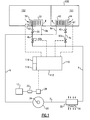
- FIG. 1 is a schematic diagram of an exemplary embodiment of a refrigerant vapor compression system associated with a two temperature controlled zones;
- FIG. 2 is a block diagram of an exemplary embodiment of a PI control process for determining the desired speed of the compression device
- FIG. 3 is a graphical illustration presenting an exemplary approach for controlling positioning of a lead liquid flow control valve
- FIG. 4 is a graphical illustration presenting another exemplary approach for controlling positioning of a lead liquid flow control valve.
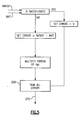
- FIG. 5 is a process flow diagram illustrating a procedure for generating an overall system temperature error for a system with two or more separate temperature controlled zones.
- FIG. 1 there are depicted an exemplary embodiment of a transport refrigeration system that includes a refrigerant vapor compression system 10 for providing the cooling capacity to chill the air within a two-compartment refrigerated cargo space 100 of a truck, a trailer, a container or the like.
- the cargo space 100 is divided into two separate and independent temperature controlled zones 101, 102 which may be chilled to different set point temperatures, whereby two different products may be shipped simultaneously.
- compartment 101 might house a perishable food product and be chilled to a box temperature above 0°C (32°F)
- compartment 102 might house a frozen product and be chilled to a box temperature below 0°C (32°F).
- the cargo space 100 is divided into two compartments, that is two separate and independent temperature-controlled zones; those skilled in the art will understand that the refrigerant vapor compression system 10 may be readily adapted for use in connection with three or more separate and independent temperature controlled zones.
- the refrigerant vapor compression system 10 includes a refrigerant vapor compression device 20, a refrigerant heat rejection heat exchanger 30, a first refrigerant evaporator 40 and a first expansion device 45 operatively associated with the first refrigerant evaporator 40, a second refrigerant evaporator 50 and a second expansion device 55 operatively associated with the second evaporator, interconnected by refrigerant lines in a closed refrigerant circuit and arranged in a conventional known refrigerant vapor compression cycle.
- Refrigerant line 2 connects the discharge outlet of the compression device 20 in refrigerant flow communication with the refrigerant inlet to the refrigerant heat rejection heat exchanger 30.
- Refrigerant line 4 connects the refrigerant outlet from the refrigerant heat rejection heat exchanger in refrigerant flow communication to refrigerant inlets to the first evaporator and the second evaporator via branch lines 4a and 4b, respectively.
- Branch lines 6a and 6b connect the refrigerant outlets of the first evaporator 40 and the second evaporator 50, respectively to refrigerant line 6 which connects in refrigerant flow communication to the suction inlet of the compression device 20.
- the refrigerant vapor compression system 20 may operate in a subcritical refrigerant cycle and be charged with a relatively high critical temperature refrigerant such as, but not limited to, hydrochlorofluorocarbons (HCFCs), such as R22, and more commonly hydrofluorocarbons (HFCs), such as R134a, R410A, R404A and R407C.
- HCFCs hydrochlorofluorocarbons
- HFCs hydrofluorocarbons
- the refrigerant heat rejection heat exchanger 30 functions as a refrigerant vapor condenser and the condenser 30, as well as both of the evaporators 40, 50, operate at refrigerant temperatures and pressures below the refrigerant's critical point.
- the refrigerant vapor compression system 20 may be charged with a relatively low critical temperature refrigerant such as carbon dioxide. Because carbon dioxide has a low critical temperature, most refrigerant vapor compression systems charged with carbon dioxide as the refrigerant are designed for operation in the transcritical pressure regime. In refrigerant vapor compression systems operating in a transcritical cycle, the refrigerant heat rejection heat exchanger 30 functions as a gas cooler rather than a condenser and operates at a refrigerant temperature and pressure in excess of the refrigerant's critical point, while the evaporators 40 and 50 operate at a refrigerant temperature and pressure in the subcritical range.
- a relatively low critical temperature refrigerant such as carbon dioxide. Because carbon dioxide has a low critical temperature, most refrigerant vapor compression systems charged with carbon dioxide as the refrigerant are designed for operation in the transcritical pressure regime.
- the refrigerant heat rejection heat exchanger 30 functions as a gas cooler rather than a condenser and operates at a refriger
- the compression device 20 comprises a variable capacity compression device such as a variable speed compression device.
- the compression device comprises a single compressor such as, for example, a single stage or multi-stage reciprocating or rotary compressor, hermetic or open, or a scroll compressor.
- the compression device 20 is not limited to a single compressor embodiment, but may comprise multiple compressors disposed in a series arrangement or a parallel arrangement or a mixed parallel and series arrangement.
- the compression device 20 is driven by a drive motor 24 operatively associated with the compression device 20 and supplied with AC electric current from a power source through a variable frequency drive 28.
- the capacity of the compression device 20 is controlled by varying the speed at which the compression device operates by varying the frequency of AC electric current supplied to the drive motor 24.
- the variable frequency drive 28, which may comprise an inverter, receives electric current at line frequency, typically 50, 55 or 60 Hertz, selectively alters that frequency, and outputs the AC current to the drive motor at the selected frequency.
- the power source comprises an electric current generator 22 driven by an internal combustion engine 12, such as the engine of the truck or trailer tractor associated with the cargo space 100 or a separate internal combustion engine dedicated to driving the electric current generator 22.
- the refrigerant vapor compression system 20 further includes a first liquid flow control valve 60a and a second liquid control valve 60b.
- the first liquid flow control valve 60a is disposed in refrigerant branch line 4a upstream with respect to refrigerant flow of the first expansion device 45.
- the second liquid flow control valve 60 b is disposed in refrigerant branch line 4b upstream with respect to refrigerant flow of the first expansion device 55.
- each of the first and second flow control valves 60a, 60b comprise two-position solenoid valves having an open position and a closed position and being selectively positionable in the open position to permit unrestricted flow therethrough, in the closed position to prevent flow therethrough, and being selectively pulse width modulated between the open and closed positions to provide restricted flow therethrough, that is flow at a percentage of the open position flow.
- the flow control valves 60a, 60b may alternatively comprise flow control valves that a selectively positionable at any desired flow opening between fully closed and fully open.
- the refrigerant vapor compression system 10 further includes a system control 110, such as a microprocessor controller having a central processing unit (CPU) 112, a memory bank 114 and an input/output interface 116.
- the system controller 110 maintains a desired temperature environment in the cargo space by selectively controlling the operation of the compressor 20, the condenser fan(s) 34 associated with the condenser heat exchanger coil 32, the evaporator fan(s) 44 associated with the first evaporator 40, the evaporator fan 54 associated with the second evaporator 50, and the opening and closing of both of the first liquid flow control valve 60a associated with the first evaporator 40 and the second liquid flow control valve 60b associated with the second evaporator 50.
- a system control 110 such as a microprocessor controller having a central processing unit (CPU) 112, a memory bank 114 and an input/output interface 116.
- the system controller 110 maintains a desired temperature environment in the cargo space by selectively controlling the operation of the compressor
- the system controller 110 controls AC electrical current from the current generator 22 (or an external AC power supply) to the compressor drive motor 24 through the variable frequency drive 28 to activate the drive motor 22 and power the compressor 20 at a desired operating speed.
- the current generator (or an external power supply) also supplies the electric current for powering the motors associated with the condenser fan(s) 34 and the evaporator fan(s) 44.
- the controller 110 also monitors operating parameters at various points in the refrigeration system through a plurality of temperature sensors and pressure transducers, not shown, as in conventional practice, such as but not limited to: an ambient air temperature sensor, a compressor suction pressure transducer, a compressor suction temperature sensor, a compressor discharge pressure transducer, and a compressor discharge temperature sensor.
- the controller 110 also monitors a return air sensor 91 that senses the temperature of the return air flow, RAT1, passing from the first compartment 101 into the first evaporator 40.
- the return air temperature, RAT1 is indicative of the temperature within the first temperature controlled zone, typically referred to as the box temperature, defined within the first compartment 101.
- the controller 110 also monitors a return air sensor 92 that senses the temperature of the return air flow, RAT2, passing from the second compartment 102 into the second evaporator 50.
- the return air temperature, RAT2 is indicative of the temperature within the second temperature controlled zone, typically referred to as the box temperature, defined within the second compartment 102.
- the system control 110 controls the refrigerant mass flow through the refrigerant circuit to provide a cooling capacity of the refrigerant vapor compression system 10 in response to a collective cooling demand for the plurality of temperature controlled zones defined within the cargo space 100, and selectively dividing the refrigerant mass flow amongst the plurality of temperature controlled zones.
- the system control 100 estimates the cooling demand of each respective zone of the two temperature controlled zones defined within the compartments 101, 102 as a function of a difference between a sensed return air temperatures RAT1, RAT2 and a related set point temperatures, RAT1SP and RAT2SP, associated respectively with the desired box temperatures for the temperature controlled zone defined within the first compartment 101 and the second temperature controlled zone defined within the second compartment 102.
- the set point temperatures RAT1SP, RAT2SP represent the estimated return air temperatures that would indicate that the desired the product storage temperatures for the particular products housed within the first compartment 101 and the second compartment 102, respectively, are being maintained under the current ambient conditions.
- the step of controlling the refrigerant mass flow may comprise: providing a variable speed compression device;_and selectively varying an operating speed of the variable speed compression device in response to a sum of the respective temperature differentials between a sensed temperature and a related set point temperature associated with each respective zone of the plurality of temperature controlled zones.
- first compartment 101 might house a perishable food product and be chilled to a box temperature above 0°C (32°F), such as about 4°C (about 40°F) or higher
- the second compartment 102 might house a frozen product and be chilled to a box temperature below 0°C (32°F), such as about -20°C (about -4°F) or lower.
- the compression device 20 is a variable speed compressor and the system controller 110 controls the cooling capacity of the refrigerant vapor compression system 10 by varying the operating speed of the compressor 20 in response to the collective cooling demand.
- the system control may process the respective sensed temperature data, RAT1 and RAT2, and the set point temperatures, RAT1SP and RAT2SP, through a PI control routine, such as shown in FIG. 2 .
- signals 201, 202 indicative of the sensed return air temperature RAT1, RAT2 is added as a negative feedback to a signal 203, 204 indicative of the associated set point temperature RAT1SP and RAT2SP at summators 205, 206, respectively to generate temperature error signals 207, 208.
- the sign of the estimate of the cooling requirement of each box is preserved by clipping the individual error signals 207 and 208 to a value of 0 whenever RAT1SP is greater than RAT1 or RAT2SP is greater than RAT2, respectively.
- the individual temperature error signals 207, 208 are then multiplied by tuning constants K p 1 K p 2, respectively, and then added at summator 209 to generate a system temperature error signal 210.
- This procedure for generating an overall system temperature error 210 for a system with two or more separate temperature controlled zones is illustrated as a process flow chart in FIG. 5 .
- the temperature error signal 210 is then processed through a PI controller 212 wherein the temperature error is multiplied by a proportional parameter, K p , which has a default valve of 1, to provide a proportional term signal 211 and multiplied by an integral time tuning parameter, K p /T i , to provide an integral term signal 214 that, after further processing as indicated in FIG. 2 , to yield a modified integral term signal 227 is added to the proportional term signal 211 at summator 220 to provide an output frequency signal, u.
- the output frequency signal u is then passed through a limit circuit 230.
- the limit circuit 230 simply outputs the received frequency signal to the inverter circuit 240 of the variable frequency drive 28 as the desired speed frequency signal, u d . However, if the output frequency signal u is less than then low limit or greater than the high limit, the limit circuit 230 adjusts the output frequency signal to the low limit or the high limit, respectively, and outputs that limited frequency signal to the inverter circuit 240 of the variable frequency drive 28 as the desired speed frequency signal, u d .
- the variable frequency drive 28 alters the frequency of the current supplied via the generator 22 to match the desired speed frequency signal, u d , and passes the electric current now at the altered frequency, u a , to the drive motor 24 for driving the compressor 20 at an operating speed commensurate with the desired speed frequency signal, u d . If the inverter circuit 240 senses that the engine driving the generator 28 is running at a low revolutions per minute, rpm, such as at idle, that the generator will be incapable of generating adequate electric current at the desired speed frequency signal, u d , the inverter circuit will limit the desired speed frequency signal according to a reduced frequency level that the engine can support at its low rpm until the engine has resumed higher rpm operation.
- the PI controller 212 may be provided with anti-windup feature.
- the anti-windup feature includes a feedback loop wherein a speed error signal 221, generated at summator 222 by subtracting the frequency signal u output from the PI controller 240 from the actual frequency, u a , output from the inverter circuit 240, is multiplied by an anti-windup tuning parameter, 1/(N i x T i ), to produce a modified error signal 223.
- the integral term signal 214 of PI controller 212 is modified at summator 224 to add the error signal 223 thereto.
- the integral term so modified is then passed through integrator 226 and the further modified integral term signal 227 is added to the proportional term signal 211 to provide the PI output frequency, u, which is passed as input to the limiter 230.
- Ni is an anti-windup tuning parameter that typically has a value of about 0.9.
- each set of tuning parameters [K p1 , T i1 ] and [K p2 , T i2 ] may be computed using conventional control tuning rules and identified plant transfer function for the particular compartment.
- the system control 110 also selectively divides the refrigerant mass flow amongst the respective temperature controlled zones defined by the compartments 101, 102.
- the system control 110 ensures that at least one of the liquid control valves 60a, 60b is in a full open position.
- the system control In an automatic mode for dividing refrigerant mass flow in a two-compartment cargo arrangement between the first evaporator 40 and the second evaporator 50, the system control identifies the compartment that has the lowest return air temperature set point is referred to as the Lag compartment and the other compartment is referred to as the Lead compartment. If only one compartment is in a cooling mode, the system control 110 will designate that compartment as the Lag compartment.
- the system control 110 will position the respective one of the flow control valves 60a, 60b associated with the Lag compartment in a full open position.
- the system control 110 will then open the other of the flow control valves 60a, 60b which is associated with the Lead compartment to the equivalent of about 17% of full open, although any other value less than 100% full open may be used, unless the sensed return air temperature for the Lead compartment is at or above a temperature value equal to the set point return air temperature for that compartment plus one-half of a designated upper set point deviation limit.
- the afore-discussed control is illustrated graphically in FIG.3 .
- the division of the refrigerant mass flow between two or more compartments by the system control 110 may also be governed by manually designating a particular compartment as the priority compartment whenever the compartment is in a cooling mode. In such case, the system controller 110 will always designate that manually selected compartment as the Lag compartment whenever that compartment is in the cooling mode, and will designate the other compartment or each of the other compartments as a Lead compartment. As in the automatic mode, in dividing the refrigerant mass flow in the manual control mode, the system control 110 will position the respective one of the flow control valves associated with the Lag compartment in a full open position.
- the control logic for the opening of the flow control valve(s) associated with the Lead compartments(s) in this manual mode where a particular compartment is manually selected as the priority compartment is illustrated graphically in FIG. 4 .
- the flow control valves 60a, 60b may comprise solenoid valves that are continuously positionable or selectively positionable at multiple openings between a fully closed position and a fully open position
- the flow control valves 60a, 60b may comprise two-position solenoid valves having a fully closed position and a fully open position, such as for example a pulse width modulated two-position solenoid valve.
- the system control 110 in order to obtain a desired flow through the flow control valve that is equivalent a desired percentage of the flow through the flow control valve it is fully open position, the system control 110 will rapidly modulate the flow control valve between the fully open position and the fully closed position to obtain the desired refrigerant mass flow through the valve.
Landscapes
- Engineering & Computer Science (AREA)
- Mechanical Engineering (AREA)
- Physics & Mathematics (AREA)
- Thermal Sciences (AREA)
- General Engineering & Computer Science (AREA)
- Chemical & Material Sciences (AREA)
- Combustion & Propulsion (AREA)
- Devices That Are Associated With Refrigeration Equipment (AREA)
- Control Of Temperature (AREA)
Claims (12)
- Procédé permettant de commander le fonctionnement d'un système de compression de vapeur de réfrigérant (10) pour le refroidissement d'un espace réfrigéré (100) comportant une pluralité de zones réfrigérées (101,102), le système de compression de vapeur de réfrigérant comprenant un circuit de réfrigérant à travers lequel on fait circuler un débit massique du réfrigérant à l'aide d'un compresseur (20), ledit procédé comprenant les étapes consistant à :commander le débit massique de réfrigérant pour créer une capacité de refroidissement du système de compression de vapeur de réfrigérant en réponse à une demande de refroidissement collective pour ladite pluralité de zones réfrigérées, l'étape de commande du débit massique de réfrigérant comprenant :l'utilisation d'un compresseur (20) à vitesse variable, etla variation sélective d'une vitesse de fonctionnement du compresseur à vitesse variable en réponse à la somme des différences respectives de température entre une température ressentie (RAT1, RAT2) et une température de consigne apparentée (RAT 1SP, RAT2SP) associée à chaque zone respective de la pluralité des zones réfrigérées : etla division sélective du débit massique de réfrigérant entre la pluralité de zones réfrigérées.
- Procédé permettant de commander le fonctionnement d'un système de compression de vapeur de réfrigérant tel que défini dans la revendication 1, comprenant également l'étape d'estimation de la demande de refroidissement provenant de chaque zone respective de la pluralité de zones réfrigérées comme une fonction de la différence entre la température ressentie et la température de consigne apparentée associée à chaque zone respective de la pluralité de zones réfrigérées.
- Procédé permettant de commander le fonctionnement d'un système de compression de vapeur de réfrigérant tel que défini dans la revendication 1 ou la revendication 2, comprenant également l'étape de détermination d'une vitesse de fonctionnement souhaité du compresseur à vitesse variable en traitant les différences respectives de température à travers un régulateur PI (212) comportant un dispositif anti-saturation.
- Procédé permettant de commander le fonctionnement d'un système de compression de vapeur de réfrigérant tel que défini dans la revendication 3, dans lequel le régulateur PI comprend un paramètre d'optimisation du temps intégré qui est une moyenne pondérée par le volume de la zone d'un ensemble de paramètres respectifs d'optimisation de temps intégrés associés à chacune de la pluralité des zones réfrigérées.
- Procédé permettant de commander le fonctionnement d'un système de compression de vapeur de réfrigérant tel que défini dans l'une quelconque des revendications précédentes, dans lequel l'étape de division sélective du débit massique de réfrigérant parmi la pluralité de zones réfrigérées comprend la division du débit massique de réfrigérant parmi la pluralité de zones réfrigérées sélectivement en réponse à une température de consigne associée à chaque zone respective de la pluralité de zones réfrigérées.
- Procédé permettant de commander le fonctionnement d'un système de compression de vapeur de réfrigérant tel que défini dans la revendication 5, dans lequel la zone réfrigérée ayant la température de consigne la moins élevée est amenée à recevoir la plus grande partie du débit massique de réfrigérant.
- Procédé permettant de commander le fonctionnement d'un système de compression de vapeur de réfrigérant tel que défini dans la revendication 5, dans lequel la zone réfrigérée ayant la température de consigne la moins élevée est manuellement identifiée pour recevoir une plus grande partie du débit massique de réfrigérant.
- Système de réfrigération (10) comprenant :un espace cargo (100) comportant une pluralité de zones réfrigérées (101,102) ;un système de compression de vapeur de réfrigérant comportant un circuit de réfrigérant comprenant un compresseur (20) à vitesse variable permettant la circulation du débit massique de réfrigérant à travers le circuit de réfrigération, une pluralité d'évaporateurs (40,50) avec au moins un évaporateur associé à chacune de la pluralité des zones réfrigérées à travers lesquelles un flux d'air circulé à partir de l'une de la pluralité des zones réfrigérées associées est passé dans une relation d'échange de chaleur avec une partie du débit massique de réfrigérant, et une pluralité de commande du flux de liquide (60a,60b) et un clapet de commande du flux de liquide étant disposé dans une association fonctionnelle avec chacun de la pluralité des évaporateurs pour réguler le flux de réfrigérant à travers celle-ci ; etun système de commande (110) permettant de commander le débit du débit massique de réfrigérant du compresseur pour créer une capacité de refroidissement du système de compression de vapeur de réfrigérant en réponse à une demande de refroidissement collectif pour la pluralité des zones réfrigérées en variant de façon sélective une vitesse de fonctionnement du compresseur à vitesse variable en réponse à une somme de différences respectives de température entre une température ressentie (RAT1, RAT2) et une température de consigne apparentée (RAT1SP, RAT2SP) associée à chaque zone respective de la pluralité des zones réfrigérées ; et pour sélectivement diviser le débit massique de réfrigérant parmi la pluralité de zones réfrigérées.
- Système frigorifique pour le transport comprenant un système de réfrigération revendiquée dans la revendication 8, dans lequel :l'espace cargo comprend un premier compartiment définissant une première zone réfrigérée (101) et un deuxième compartiment définissant une deuxième zone réfrigérée (102) ;le système de compression de vapeur de réfrigérant comprend un premier évaporateur (40) à travers lequel un flux d'air circulé à partir de la première zone réfrigérée est passé dans une relation d'échange de température avec une première partie du débit massique de réfrigérant, un deuxième évaporateur à travers lequel un flux d'air circulé à partir de la deuxième zone réfrigérée est passé dans une relation d'échange de chaleur avec une deuxième partie du débit massique de réfrigérant, un premier clapet de commande de flux de liquide (60a) disposé dans le circuit du réfrigérant pour la régulation du flux de réfrigérant à travers le premier évaporateur et un deuxième clapet de commande du flux de liquide (60b) disposé dans le circuit de réfrigérant pour la régulation du flux de réfrigérant à travers le deuxième évaporateur ; etsystème de commande permettant de commander le débit du débit massique de réfrigérant du compresseur pour créer une capacité de refroidissement du système de compression de vapeur de réfrigérant en réponse à une demande de refroidissement collectif pour la première et la deuxième zone réfrigérées, et pour commander de façon sélective le positionnement du premier clapet de commande du flux de liquide pour commander le flux massique de la première partie du débit massique de réfrigérant allant vers le premier évaporateur, et pour commander de façon sélective le positionnement du deuxième clapet de commande du flux de liquide pour commander le flux massique de la deuxième partie du débit massique de réfrigérant allant vers le deuxième évaporateur.
- Système frigorifique pour le transport tel que décrit dans la revendication 9, comprenant également :un moteur à vitesse variable (28) permettant de faire fonctionner le compresseur à vitesse variable à une vitesse de fonctionnement souhaitée ; etune transmission à fréquence variable associée de façon fonctionnelle au système commande et au moteur à vitesse variable pour alimenter en courant électrique le moteur à vitesse variable à une fréquence souhaitée en réponse à un signal de fréquence provenant du système de commande.
- Système frigorifique de transport tel que défini dans la revendication 9 ou 10, dans lequel chacun du premier et du second clapet de commande du flux de liquide contient une électrovanne ayant une position complètement ouverte et une position complètement fermée.
- Système frigorifique de transport tel que défini dans la revendication 11, dans lequel chacun du premier et du deuxième électrovannes peut être modulé par une impulsion en durée entre une position complètement ouverte et une position complètement fermée.
Applications Claiming Priority (2)
| Application Number | Priority Date | Filing Date | Title |
|---|---|---|---|
| US11013708P | 2008-10-31 | 2008-10-31 | |
| PCT/US2009/061459 WO2010051198A2 (fr) | 2008-10-31 | 2009-10-21 | Commande de systèmes de compression de vapeur de réfrigérant à zones multiples |
Publications (3)
| Publication Number | Publication Date |
|---|---|
| EP2362932A2 EP2362932A2 (fr) | 2011-09-07 |
| EP2362932A4 EP2362932A4 (fr) | 2012-10-24 |
| EP2362932B1 true EP2362932B1 (fr) | 2013-12-04 |
Family
ID=42129512
Family Applications (1)
| Application Number | Title | Priority Date | Filing Date |
|---|---|---|---|
| EP09824023.7A Active EP2362932B1 (fr) | 2008-10-31 | 2009-10-21 | Commande de systèmes de compression de vapeur de réfrigérant à zones multiples |
Country Status (4)
| Country | Link |
|---|---|
| US (1) | US9297548B2 (fr) |
| EP (1) | EP2362932B1 (fr) |
| CN (1) | CN102203515A (fr) |
| WO (1) | WO2010051198A2 (fr) |
Families Citing this family (53)
| Publication number | Priority date | Publication date | Assignee | Title |
|---|---|---|---|---|
| US20120000222A1 (en) * | 2010-06-30 | 2012-01-05 | Thermo King Corporation | Zone priority temperature control in a multiple zone transport refrigeration system |
| US10266034B2 (en) * | 2011-06-16 | 2019-04-23 | Hamilton Sundstrand Corporation | Heat pump for supplemental heat |
| WO2013019537A2 (fr) * | 2011-07-29 | 2013-02-07 | Carrier Corporation | Systèmes de chauffage, de ventilation et de climatisation |
| CN102506498B (zh) * | 2011-09-28 | 2014-02-05 | 奇瑞汽车股份有限公司 | 一种汽车双蒸发器空调系统的控制方法 |
| US9285153B2 (en) | 2011-10-19 | 2016-03-15 | Thermo Fisher Scientific (Asheville) Llc | High performance refrigerator having passive sublimation defrost of evaporator |
| US9310121B2 (en) | 2011-10-19 | 2016-04-12 | Thermo Fisher Scientific (Asheville) Llc | High performance refrigerator having sacrificial evaporator |
| US9188369B2 (en) * | 2012-04-02 | 2015-11-17 | Whirlpool Corporation | Fin-coil design for a dual suction air conditioning unit |
| US9776473B2 (en) | 2012-09-20 | 2017-10-03 | Thermo King Corporation | Electrical transport refrigeration system |
| WO2014103339A1 (fr) * | 2012-12-28 | 2014-07-03 | ダイキン工業株式会社 | Dispositif de réfrigération |
| CN103162475B (zh) * | 2013-03-22 | 2015-04-15 | 青岛海信日立空调系统有限公司 | 一种空调散热循环系统 |
| DE102013207449A1 (de) * | 2013-04-24 | 2014-10-30 | Dürr Systems GmbH | Verfahren zum Konditionieren von Luft und Konditionieranlage |
| EP3014197B1 (fr) | 2013-06-26 | 2022-01-12 | Carrier Corporation | Système de réfrigération de transport à compartiments multiples ayant une vanne d'isolement d'évaporateur |
| EP3073214A4 (fr) * | 2013-11-18 | 2016-11-16 | Chillida Vicente Ávila | Système de réfrigération industriel |
| JP2015129625A (ja) * | 2013-12-02 | 2015-07-16 | 三星電子株式会社Samsung Electronics Co.,Ltd. | 冷却装置 |
| US10337767B2 (en) * | 2014-01-08 | 2019-07-02 | Carrier Corporation | Adaptive control of multi-compartment transport refrigeration system |
| CN104833153B (zh) * | 2014-02-11 | 2018-02-09 | 珠海格力电器股份有限公司 | 船用水冷机组的控制电路及方法 |
| US9925847B2 (en) | 2014-03-10 | 2018-03-27 | Tiger Tool International Incorporated | Heating and cooling systems and methods for truck cabs |
| US10254027B2 (en) | 2014-05-02 | 2019-04-09 | Thermo King Corporation | Method and system for controlling operation of evaporator fans in a transport refrigeration system |
| US10119738B2 (en) | 2014-09-26 | 2018-11-06 | Waterfurnace International Inc. | Air conditioning system with vapor injection compressor |
| RU2599822C1 (ru) * | 2015-06-11 | 2016-10-20 | Федеральное государственное бюджетное учреждение науки Казанский физико-технический институт им. Е.К. Завойского Казанского научного центра Российской Академии наук (КФТИ КазНЦ РАН) | Блок управления устройства подачи хладагента |
| CN108351140B (zh) | 2015-11-03 | 2021-07-09 | 开利公司 | 运输制冷系统和操作方法 |
| US10625561B2 (en) | 2015-11-13 | 2020-04-21 | Thermo King Corporation | Methods and systems for coordinated zone operation of a multi-zone transport refrigeration system |
| US10543737B2 (en) | 2015-12-28 | 2020-01-28 | Thermo King Corporation | Cascade heat transfer system |
| WO2017132260A1 (fr) | 2016-01-25 | 2017-08-03 | Tiger Tool Intenational Incorporated | Systèmes et procédés de climatisation destinés à un véhicule |
| US10378816B2 (en) * | 2016-03-14 | 2019-08-13 | Hector Delgadillo | Air over air refrigeration system |
| US10175081B2 (en) * | 2016-06-24 | 2019-01-08 | Thermo King Corporation | Fluid level measurement |
| US10871314B2 (en) | 2016-07-08 | 2020-12-22 | Climate Master, Inc. | Heat pump and water heater |
| US10866002B2 (en) | 2016-11-09 | 2020-12-15 | Climate Master, Inc. | Hybrid heat pump with improved dehumidification |
| US11535425B2 (en) | 2016-11-22 | 2022-12-27 | Dometic Sweden Ab | Cooler |
| USD933449S1 (en) | 2016-11-22 | 2021-10-19 | Dometic Sweden Ab | Latch |
| EP3513128B1 (fr) * | 2016-12-13 | 2020-05-13 | Oblamatik AG | Procédé de chauffage ou de refroidissement de pièces d'un bâtiment |
| USD836993S1 (en) | 2017-05-17 | 2019-01-01 | Dometic Sweden Ab | Cooler |
| USD836994S1 (en) | 2017-05-17 | 2019-01-01 | Dometic Sweden Ab | Cooler |
| US10857851B2 (en) | 2017-09-26 | 2020-12-08 | Emerson Climate Technologies, Inc. | Compressor discharge pressure based control systems and methods |
| CN111263958B (zh) * | 2017-10-30 | 2022-05-27 | 开利公司 | 检测器装置中的补偿器 |
| US10935260B2 (en) | 2017-12-12 | 2021-03-02 | Climate Master, Inc. | Heat pump with dehumidification |
| KR102455048B1 (ko) * | 2017-12-13 | 2022-10-14 | 엘지전자 주식회사 | 냉장고 |
| US20190316828A1 (en) * | 2018-04-13 | 2019-10-17 | Carrier Corporation | Transportation refrigeration system having multiple fans |
| US11098943B2 (en) * | 2018-04-13 | 2021-08-24 | Carrier Corporation | Transportation refrigeration system with unequal sized heat exchangers |
| US10317123B1 (en) | 2018-04-16 | 2019-06-11 | Sub-Zero, Inc. | Shared evaporator system |
| US11407283B2 (en) | 2018-04-30 | 2022-08-09 | Tiger Tool International Incorporated | Cab heating systems and methods for vehicles |
| CN110579075B (zh) * | 2018-06-11 | 2021-10-01 | 惠而浦(中国)股份有限公司 | 一种冰箱变频负载转速控制方法及系统 |
| KR102530943B1 (ko) * | 2018-07-25 | 2023-05-11 | 현대자동차주식회사 | 차량의 열관리 시스템 |
| US11592215B2 (en) | 2018-08-29 | 2023-02-28 | Waterfurnace International, Inc. | Integrated demand water heating using a capacity modulated heat pump with desuperheater |
| US11993130B2 (en) | 2018-11-05 | 2024-05-28 | Tiger Tool International Incorporated | Cooling systems and methods for vehicle cabs |
| CA3081986A1 (fr) | 2019-07-15 | 2021-01-15 | Climate Master, Inc. | Systeme de conditionnement d`air a regulation de puissance et production d`eau chaude controlee |
| US11402145B1 (en) | 2020-03-24 | 2022-08-02 | Sub-Zero Group, Inc. | Split air flow system |
| US12030368B2 (en) | 2020-07-02 | 2024-07-09 | Tiger Tool International Incorporated | Compressor systems and methods for use by vehicle heating, ventilating, and air conditioning systems |
| EP4000976A1 (fr) * | 2020-11-19 | 2022-05-25 | Carrier Corporation | Unité de réfrigération de transport avec commande de réfrigération électrique à vitesse variable et source d'alimentation de générateur synchrone de moteur diesel à vitesse variable |
| US11662104B2 (en) * | 2021-03-26 | 2023-05-30 | First Co. | Independent temperature control for rooms |
| US12181189B2 (en) | 2021-11-10 | 2024-12-31 | Climate Master, Inc. | Ceiling-mountable heat pump system |
| US11761661B2 (en) | 2021-12-02 | 2023-09-19 | Johnson Controls Tyco IP Holdings LLP | Systems and methods for operating an HVAC system |
| DE102021214679A1 (de) | 2021-12-20 | 2023-06-22 | Robert Bosch Gesellschaft mit beschränkter Haftung | Verfahren zur Steuerung einer Kreisprozessanlage und Kompressionsanordnung |
Family Cites Families (14)
| Publication number | Priority date | Publication date | Assignee | Title |
|---|---|---|---|---|
| US4487028A (en) * | 1983-09-22 | 1984-12-11 | The Trane Company | Control for a variable capacity temperature conditioning system |
| JP2983269B2 (ja) * | 1990-09-14 | 1999-11-29 | 株式会社東芝 | 空気調和機 |
| JPH04270854A (ja) * | 1991-02-26 | 1992-09-28 | Hitachi Ltd | 空気調和機の制御方法 |
| US6102114A (en) * | 1997-09-30 | 2000-08-15 | Matsushita Electric Industrial Co., Ltd. | Multi-room air conditioning system |
| WO2000065288A1 (fr) * | 1999-04-28 | 2000-11-02 | Thermo King Corporation | Unite de regulation de temperature de transport |
| US6415619B1 (en) * | 2001-03-09 | 2002-07-09 | Hewlett-Packard Company | Multi-load refrigeration system with multiple parallel evaporators |
| JP4028688B2 (ja) * | 2001-03-21 | 2007-12-26 | 株式会社東芝 | 冷蔵庫 |
| US6662865B2 (en) * | 2001-04-30 | 2003-12-16 | Hewlett-Packard Development Company, L.P. | Multi-load thermal regulating system having electronic valve control |
| JP2003166764A (ja) * | 2001-09-20 | 2003-06-13 | Denso Corp | 冷凍サイクル装置 |
| JP4131630B2 (ja) | 2002-02-26 | 2008-08-13 | 松下電器産業株式会社 | 多室形空気調和装置及びその制御方法 |
| US7262536B2 (en) * | 2003-08-11 | 2007-08-28 | General Motors Corporation | Gearless wheel motor drive system |
| US6981381B1 (en) * | 2003-12-16 | 2006-01-03 | Lattice Semiconductor Corp. | Linear thermoelectric device driver |
| US7797957B2 (en) * | 2006-04-12 | 2010-09-21 | Hussmann Corporation | Methods and apparatus for linearized temperature control of commercial refrigeration systems |
| FR2912084B1 (fr) | 2007-02-01 | 2011-06-24 | Valeo Systemes Thermiques | Installation de climatisation munie d'un dispositif de controle de givrage |
-
2009
- 2009-10-21 WO PCT/US2009/061459 patent/WO2010051198A2/fr not_active Ceased
- 2009-10-21 CN CN2009801432457A patent/CN102203515A/zh active Pending
- 2009-10-21 EP EP09824023.7A patent/EP2362932B1/fr active Active
- 2009-10-21 US US13/126,296 patent/US9297548B2/en active Active
Also Published As
| Publication number | Publication date |
|---|---|
| US9297548B2 (en) | 2016-03-29 |
| EP2362932A2 (fr) | 2011-09-07 |
| WO2010051198A3 (fr) | 2010-09-02 |
| EP2362932A4 (fr) | 2012-10-24 |
| CN102203515A (zh) | 2011-09-28 |
| WO2010051198A2 (fr) | 2010-05-06 |
| US20110209490A1 (en) | 2011-09-01 |
Similar Documents
| Publication | Publication Date | Title |
|---|---|---|
| EP2362932B1 (fr) | Commande de systèmes de compression de vapeur de réfrigérant à zones multiples | |
| US10451325B2 (en) | Transcritical refrigerant vapor compression system high side pressure control | |
| EP2888543B1 (fr) | Transition d'étages dans un système de compression de vapeur de réfrigérant transcritique | |
| EP2220450B2 (fr) | Système de réfrigération de transport et procédé de commande | |
| EP2737265B1 (fr) | Logique de commande de la température pour système de réfrigération | |
| US9995515B2 (en) | Frozen evaporator coil detection and defrost initiation | |
| US9739519B2 (en) | Startup logic for refrigeration system | |
| EP3377830B1 (fr) | Procédé de détection d'une perte de charge de réfrigérant d'un système de réfrigération | |
| EP2643177B1 (fr) | Commande de limite de courant sur un système de réfrigération de transport | |
| EP2823239B1 (fr) | Gestion de démarrage noyé de compresseur intelligent | |
| EP3243032B1 (fr) | Commande de variateur de fréquence (vfd) pour système frigorifique à plusieurs circuits | |
| EP3414499B1 (fr) | Gestion de puissance pour système de réfrigération de transport de co2 | |
| HK1162652A (en) | Control of multiple zone refrigerant vapor compression systems |
Legal Events
| Date | Code | Title | Description |
|---|---|---|---|
| PUAI | Public reference made under article 153(3) epc to a published international application that has entered the european phase |
Free format text: ORIGINAL CODE: 0009012 |
|
| 17P | Request for examination filed |
Effective date: 20110415 |
|
| AK | Designated contracting states |
Kind code of ref document: A2 Designated state(s): AT BE BG CH CY CZ DE DK EE ES FI FR GB GR HR HU IE IS IT LI LT LU LV MC MK MT NL NO PL PT RO SE SI SK SM TR |
|
| DAX | Request for extension of the european patent (deleted) | ||
| A4 | Supplementary search report drawn up and despatched |
Effective date: 20120920 |
|
| RIC1 | Information provided on ipc code assigned before grant |
Ipc: B60H 1/00 20060101ALI20120914BHEP Ipc: B60H 1/32 20060101ALI20120914BHEP Ipc: F24F 11/02 20060101AFI20120914BHEP Ipc: F25B 49/02 20060101ALI20120914BHEP Ipc: F24F 11/00 20060101ALI20120914BHEP Ipc: F25B 5/02 20060101ALI20120914BHEP |
|
| GRAP | Despatch of communication of intention to grant a patent |
Free format text: ORIGINAL CODE: EPIDOSNIGR1 |
|
| RIC1 | Information provided on ipc code assigned before grant |
Ipc: F24F 11/00 20060101ALI20130510BHEP Ipc: F24F 11/02 20060101AFI20130510BHEP Ipc: B60H 1/32 20060101ALI20130510BHEP Ipc: F25D 29/00 20060101ALI20130510BHEP Ipc: F25B 49/02 20060101ALI20130510BHEP Ipc: B60H 1/00 20060101ALI20130510BHEP Ipc: F25B 5/02 20060101ALI20130510BHEP |
|
| INTG | Intention to grant announced |
Effective date: 20130611 |
|
| GRAS | Grant fee paid |
Free format text: ORIGINAL CODE: EPIDOSNIGR3 |
|
| GRAA | (expected) grant |
Free format text: ORIGINAL CODE: 0009210 |
|
| AK | Designated contracting states |
Kind code of ref document: B1 Designated state(s): AT BE BG CH CY CZ DE DK EE ES FI FR GB GR HR HU IE IS IT LI LT LU LV MC MK MT NL NO PL PT RO SE SI SK SM TR |
|
| REG | Reference to a national code |
Ref country code: GB Ref legal event code: FG4D |
|
| REG | Reference to a national code |
Ref country code: CH Ref legal event code: EP |
|
| REG | Reference to a national code |
Ref country code: AT Ref legal event code: REF Ref document number: 643690 Country of ref document: AT Kind code of ref document: T Effective date: 20140115 Ref country code: IE Ref legal event code: FG4D |
|
| REG | Reference to a national code |
Ref country code: DE Ref legal event code: R096 Ref document number: 602009020578 Country of ref document: DE Effective date: 20140130 |
|
| REG | Reference to a national code |
Ref country code: NL Ref legal event code: VDEP Effective date: 20131204 |
|
| REG | Reference to a national code |
Ref country code: AT Ref legal event code: MK05 Ref document number: 643690 Country of ref document: AT Kind code of ref document: T Effective date: 20131204 |
|
| PG25 | Lapsed in a contracting state [announced via postgrant information from national office to epo] |
Ref country code: NL Free format text: LAPSE BECAUSE OF FAILURE TO SUBMIT A TRANSLATION OF THE DESCRIPTION OR TO PAY THE FEE WITHIN THE PRESCRIBED TIME-LIMIT Effective date: 20131204 Ref country code: FI Free format text: LAPSE BECAUSE OF FAILURE TO SUBMIT A TRANSLATION OF THE DESCRIPTION OR TO PAY THE FEE WITHIN THE PRESCRIBED TIME-LIMIT Effective date: 20131204 Ref country code: LT Free format text: LAPSE BECAUSE OF FAILURE TO SUBMIT A TRANSLATION OF THE DESCRIPTION OR TO PAY THE FEE WITHIN THE PRESCRIBED TIME-LIMIT Effective date: 20131204 Ref country code: HR Free format text: LAPSE BECAUSE OF FAILURE TO SUBMIT A TRANSLATION OF THE DESCRIPTION OR TO PAY THE FEE WITHIN THE PRESCRIBED TIME-LIMIT Effective date: 20131204 Ref country code: SE Free format text: LAPSE BECAUSE OF FAILURE TO SUBMIT A TRANSLATION OF THE DESCRIPTION OR TO PAY THE FEE WITHIN THE PRESCRIBED TIME-LIMIT Effective date: 20131204 Ref country code: NO Free format text: LAPSE BECAUSE OF FAILURE TO SUBMIT A TRANSLATION OF THE DESCRIPTION OR TO PAY THE FEE WITHIN THE PRESCRIBED TIME-LIMIT Effective date: 20140304 |
|
| REG | Reference to a national code |
Ref country code: LT Ref legal event code: MG4D |
|
| PG25 | Lapsed in a contracting state [announced via postgrant information from national office to epo] |
Ref country code: LV Free format text: LAPSE BECAUSE OF FAILURE TO SUBMIT A TRANSLATION OF THE DESCRIPTION OR TO PAY THE FEE WITHIN THE PRESCRIBED TIME-LIMIT Effective date: 20131204 Ref country code: CY Free format text: LAPSE BECAUSE OF FAILURE TO SUBMIT A TRANSLATION OF THE DESCRIPTION OR TO PAY THE FEE WITHIN THE PRESCRIBED TIME-LIMIT Effective date: 20131204 Ref country code: AT Free format text: LAPSE BECAUSE OF FAILURE TO SUBMIT A TRANSLATION OF THE DESCRIPTION OR TO PAY THE FEE WITHIN THE PRESCRIBED TIME-LIMIT Effective date: 20131204 |
|
| PG25 | Lapsed in a contracting state [announced via postgrant information from national office to epo] |
Ref country code: BE Free format text: LAPSE BECAUSE OF FAILURE TO SUBMIT A TRANSLATION OF THE DESCRIPTION OR TO PAY THE FEE WITHIN THE PRESCRIBED TIME-LIMIT Effective date: 20131204 Ref country code: EE Free format text: LAPSE BECAUSE OF FAILURE TO SUBMIT A TRANSLATION OF THE DESCRIPTION OR TO PAY THE FEE WITHIN THE PRESCRIBED TIME-LIMIT Effective date: 20131204 Ref country code: IS Free format text: LAPSE BECAUSE OF FAILURE TO SUBMIT A TRANSLATION OF THE DESCRIPTION OR TO PAY THE FEE WITHIN THE PRESCRIBED TIME-LIMIT Effective date: 20140404 |
|
| PG25 | Lapsed in a contracting state [announced via postgrant information from national office to epo] |
Ref country code: PL Free format text: LAPSE BECAUSE OF FAILURE TO SUBMIT A TRANSLATION OF THE DESCRIPTION OR TO PAY THE FEE WITHIN THE PRESCRIBED TIME-LIMIT Effective date: 20131204 Ref country code: RO Free format text: LAPSE BECAUSE OF FAILURE TO SUBMIT A TRANSLATION OF THE DESCRIPTION OR TO PAY THE FEE WITHIN THE PRESCRIBED TIME-LIMIT Effective date: 20131204 Ref country code: ES Free format text: LAPSE BECAUSE OF FAILURE TO SUBMIT A TRANSLATION OF THE DESCRIPTION OR TO PAY THE FEE WITHIN THE PRESCRIBED TIME-LIMIT Effective date: 20131204 Ref country code: PT Free format text: LAPSE BECAUSE OF FAILURE TO SUBMIT A TRANSLATION OF THE DESCRIPTION OR TO PAY THE FEE WITHIN THE PRESCRIBED TIME-LIMIT Effective date: 20140404 Ref country code: SK Free format text: LAPSE BECAUSE OF FAILURE TO SUBMIT A TRANSLATION OF THE DESCRIPTION OR TO PAY THE FEE WITHIN THE PRESCRIBED TIME-LIMIT Effective date: 20131204 Ref country code: CZ Free format text: LAPSE BECAUSE OF FAILURE TO SUBMIT A TRANSLATION OF THE DESCRIPTION OR TO PAY THE FEE WITHIN THE PRESCRIBED TIME-LIMIT Effective date: 20131204 |
|
| REG | Reference to a national code |
Ref country code: DE Ref legal event code: R097 Ref document number: 602009020578 Country of ref document: DE |
|
| PLBE | No opposition filed within time limit |
Free format text: ORIGINAL CODE: 0009261 |
|
| STAA | Information on the status of an ep patent application or granted ep patent |
Free format text: STATUS: NO OPPOSITION FILED WITHIN TIME LIMIT |
|
| PG25 | Lapsed in a contracting state [announced via postgrant information from national office to epo] |
Ref country code: DK Free format text: LAPSE BECAUSE OF FAILURE TO SUBMIT A TRANSLATION OF THE DESCRIPTION OR TO PAY THE FEE WITHIN THE PRESCRIBED TIME-LIMIT Effective date: 20131204 |
|
| 26N | No opposition filed |
Effective date: 20140905 |
|
| REG | Reference to a national code |
Ref country code: DE Ref legal event code: R097 Ref document number: 602009020578 Country of ref document: DE Effective date: 20140905 |
|
| PG25 | Lapsed in a contracting state [announced via postgrant information from national office to epo] |
Ref country code: SI Free format text: LAPSE BECAUSE OF FAILURE TO SUBMIT A TRANSLATION OF THE DESCRIPTION OR TO PAY THE FEE WITHIN THE PRESCRIBED TIME-LIMIT Effective date: 20131204 |
|
| PG25 | Lapsed in a contracting state [announced via postgrant information from national office to epo] |
Ref country code: MC Free format text: LAPSE BECAUSE OF FAILURE TO SUBMIT A TRANSLATION OF THE DESCRIPTION OR TO PAY THE FEE WITHIN THE PRESCRIBED TIME-LIMIT Effective date: 20131204 Ref country code: LU Free format text: LAPSE BECAUSE OF FAILURE TO SUBMIT A TRANSLATION OF THE DESCRIPTION OR TO PAY THE FEE WITHIN THE PRESCRIBED TIME-LIMIT Effective date: 20141021 |
|
| REG | Reference to a national code |
Ref country code: CH Ref legal event code: PL |
|
| REG | Reference to a national code |
Ref country code: IE Ref legal event code: MM4A |
|
| PG25 | Lapsed in a contracting state [announced via postgrant information from national office to epo] |
Ref country code: LI Free format text: LAPSE BECAUSE OF NON-PAYMENT OF DUE FEES Effective date: 20141031 Ref country code: CH Free format text: LAPSE BECAUSE OF NON-PAYMENT OF DUE FEES Effective date: 20141031 |
|
| PG25 | Lapsed in a contracting state [announced via postgrant information from national office to epo] |
Ref country code: IT Free format text: LAPSE BECAUSE OF FAILURE TO SUBMIT A TRANSLATION OF THE DESCRIPTION OR TO PAY THE FEE WITHIN THE PRESCRIBED TIME-LIMIT Effective date: 20131204 |
|
| PG25 | Lapsed in a contracting state [announced via postgrant information from national office to epo] |
Ref country code: IE Free format text: LAPSE BECAUSE OF NON-PAYMENT OF DUE FEES Effective date: 20141021 |
|
| PG25 | Lapsed in a contracting state [announced via postgrant information from national office to epo] |
Ref country code: SM Free format text: LAPSE BECAUSE OF FAILURE TO SUBMIT A TRANSLATION OF THE DESCRIPTION OR TO PAY THE FEE WITHIN THE PRESCRIBED TIME-LIMIT Effective date: 20131204 |
|
| PG25 | Lapsed in a contracting state [announced via postgrant information from national office to epo] |
Ref country code: BG Free format text: LAPSE BECAUSE OF FAILURE TO SUBMIT A TRANSLATION OF THE DESCRIPTION OR TO PAY THE FEE WITHIN THE PRESCRIBED TIME-LIMIT Effective date: 20131204 Ref country code: GR Free format text: LAPSE BECAUSE OF FAILURE TO SUBMIT A TRANSLATION OF THE DESCRIPTION OR TO PAY THE FEE WITHIN THE PRESCRIBED TIME-LIMIT Effective date: 20140305 |
|
| PG25 | Lapsed in a contracting state [announced via postgrant information from national office to epo] |
Ref country code: HU Free format text: LAPSE BECAUSE OF FAILURE TO SUBMIT A TRANSLATION OF THE DESCRIPTION OR TO PAY THE FEE WITHIN THE PRESCRIBED TIME-LIMIT; INVALID AB INITIO Effective date: 20091021 Ref country code: TR Free format text: LAPSE BECAUSE OF FAILURE TO SUBMIT A TRANSLATION OF THE DESCRIPTION OR TO PAY THE FEE WITHIN THE PRESCRIBED TIME-LIMIT Effective date: 20131204 Ref country code: MT Free format text: LAPSE BECAUSE OF FAILURE TO SUBMIT A TRANSLATION OF THE DESCRIPTION OR TO PAY THE FEE WITHIN THE PRESCRIBED TIME-LIMIT Effective date: 20131204 |
|
| REG | Reference to a national code |
Ref country code: FR Ref legal event code: PLFP Year of fee payment: 8 |
|
| REG | Reference to a national code |
Ref country code: DE Ref legal event code: R082 Ref document number: 602009020578 Country of ref document: DE Representative=s name: SCHMITT-NILSON SCHRAUD WAIBEL WOHLFROM PATENTA, DE |
|
| REG | Reference to a national code |
Ref country code: FR Ref legal event code: PLFP Year of fee payment: 9 |
|
| REG | Reference to a national code |
Ref country code: DE Ref legal event code: R079 Ref document number: 602009020578 Country of ref document: DE Free format text: PREVIOUS MAIN CLASS: F24F0011020000 Ipc: F24F0011890000 |
|
| PG25 | Lapsed in a contracting state [announced via postgrant information from national office to epo] |
Ref country code: MK Free format text: LAPSE BECAUSE OF FAILURE TO SUBMIT A TRANSLATION OF THE DESCRIPTION OR TO PAY THE FEE WITHIN THE PRESCRIBED TIME-LIMIT Effective date: 20131204 |
|
| REG | Reference to a national code |
Ref country code: FR Ref legal event code: PLFP Year of fee payment: 10 |
|
| PGFP | Annual fee paid to national office [announced via postgrant information from national office to epo] |
Ref country code: GB Payment date: 20250923 Year of fee payment: 17 |
|
| PGFP | Annual fee paid to national office [announced via postgrant information from national office to epo] |
Ref country code: FR Payment date: 20250924 Year of fee payment: 17 |
|
| PGFP | Annual fee paid to national office [announced via postgrant information from national office to epo] |
Ref country code: DE Payment date: 20250923 Year of fee payment: 17 |