EP2363077A1 - Instrument chirurgical doté d'une caméra sans fil intégrée - Google Patents
Instrument chirurgical doté d'une caméra sans fil intégrée Download PDFInfo
- Publication number
- EP2363077A1 EP2363077A1 EP11250253A EP11250253A EP2363077A1 EP 2363077 A1 EP2363077 A1 EP 2363077A1 EP 11250253 A EP11250253 A EP 11250253A EP 11250253 A EP11250253 A EP 11250253A EP 2363077 A1 EP2363077 A1 EP 2363077A1
- Authority
- EP
- European Patent Office
- Prior art keywords
- surgical instrument
- signal
- image sensor
- control circuitry
- wireless receiver
- Prior art date
- Legal status (The legal status is an assumption and is not a legal conclusion. Google has not performed a legal analysis and makes no representation as to the accuracy of the status listed.)
- Withdrawn
Links
- 238000000034 method Methods 0.000 claims abstract description 13
- 239000012636 effector Substances 0.000 claims abstract description 7
- 230000003287 optical effect Effects 0.000 claims abstract description 7
- 230000005540 biological transmission Effects 0.000 claims description 4
- 238000012545 processing Methods 0.000 description 10
- 238000002355 open surgical procedure Methods 0.000 description 3
- 238000001356 surgical procedure Methods 0.000 description 3
- 238000002324 minimally invasive surgery Methods 0.000 description 2
- 238000012978 minimally invasive surgical procedure Methods 0.000 description 2
- 238000012986 modification Methods 0.000 description 2
- 230000004048 modification Effects 0.000 description 2
- 238000011084 recovery Methods 0.000 description 2
- 241001631457 Cannula Species 0.000 description 1
- 238000004891 communication Methods 0.000 description 1
- 230000008878 coupling Effects 0.000 description 1
- 238000010168 coupling process Methods 0.000 description 1
- 238000005859 coupling reaction Methods 0.000 description 1
- 238000005516 engineering process Methods 0.000 description 1
- 238000002357 laparoscopic surgery Methods 0.000 description 1
- 238000012830 laparoscopic surgical procedure Methods 0.000 description 1
- 210000000056 organ Anatomy 0.000 description 1
- 230000037390 scarring Effects 0.000 description 1
- 238000012546 transfer Methods 0.000 description 1
Images

Classifications
-
- A—HUMAN NECESSITIES
- A61—MEDICAL OR VETERINARY SCIENCE; HYGIENE
- A61B—DIAGNOSIS; SURGERY; IDENTIFICATION
- A61B17/00—Surgical instruments, devices or methods
- A61B17/28—Surgical forceps
- A61B17/29—Forceps for use in minimally invasive surgery
-
- A—HUMAN NECESSITIES
- A61—MEDICAL OR VETERINARY SCIENCE; HYGIENE
- A61B—DIAGNOSIS; SURGERY; IDENTIFICATION
- A61B17/00—Surgical instruments, devices or methods
- A61B2017/00017—Electrical control of surgical instruments
- A61B2017/00221—Electrical control of surgical instruments with wireless transmission of data, e.g. by infrared radiation or radiowaves
-
- A—HUMAN NECESSITIES
- A61—MEDICAL OR VETERINARY SCIENCE; HYGIENE
- A61B—DIAGNOSIS; SURGERY; IDENTIFICATION
- A61B90/00—Instruments, implements or accessories specially adapted for surgery or diagnosis and not covered by any of the groups A61B1/00 - A61B50/00, e.g. for luxation treatment or for protecting wound edges
- A61B90/36—Image-producing devices or illumination devices not otherwise provided for
- A61B90/37—Surgical systems with images on a monitor during operation
- A61B2090/373—Surgical systems with images on a monitor during operation using light, e.g. by using optical scanners
-
- A—HUMAN NECESSITIES
- A61—MEDICAL OR VETERINARY SCIENCE; HYGIENE
- A61B—DIAGNOSIS; SURGERY; IDENTIFICATION
- A61B90/00—Instruments, implements or accessories specially adapted for surgery or diagnosis and not covered by any of the groups A61B1/00 - A61B50/00, e.g. for luxation treatment or for protecting wound edges
- A61B90/36—Image-producing devices or illumination devices not otherwise provided for
- A61B90/361—Image-producing devices, e.g. surgical cameras
Definitions
- the present disclosure relates to a wireless camera, and more particularly, to a surgical instrument including an integrated wireless video camera for use in laparoscopic surgeries.
- Laparoscopic surgical procedures are minimally invasive procedures in which operations are carried out within the body by means of elongated instruments inserted through small incisions in the body. The incisions are typically created by a tissue piercing instrument such as a trocar. Laparoscopic instruments are inserted into the patient through a cannula or port which maintains the incision opening in the body during the procedure.
- Laparoscopic procedures are desirable in that they allow for quicker recovery time and shorter hospital stays as compared to open surgical procedures. Laparoscopic procedures also leave minimal scarring (both internally and externally) and reduce patient discomfort during the recovery period.
- a surgical instrument for use in laparoscopic procedures which includes an integrated wireless camera capable of providing the surgeon with a real-time video image of the surgical site. Further, a surgical instrument including an integrated wireless camera would free up and/or reduce the number of access ports required for a particular procedure since a separate port for an endoscope would no longer be required.
- a surgical instrument having an integrated wireless camera includes a handle assembly housing control circuitry, e.g., a processing component and a wireless transmitter.
- An elongated shaft extends from the handle assembly and includes an end effector disposed at a distal end thereof.
- An image sensor assembly e.g., a lens and an image sensor, is disposed toward the distal end of the elongated shaft.
- the image sensor assembly is electrically coupled to the control circuitry disposed within the handle. In operation, the image sensor assembly converts an optical image to an electrical signal.
- the electrical signal is communicated to the control circuitry where it is processed, e.g., converted from analog to digital or from digital to analog.
- the processed signal is wirelessly transmitted to a wireless receiver positioned remote of the surgical instrument.
- the surgical instrument further includes an antenna mounted on the handle assembly.
- the antenna may be disposed within the handle. The antenna is configured to facilitate the transmission of the processed signal from the wireless transmitter to the wireless receiver.
- the wireless receiver is coupled to a video display for displaying the transmitted signal as a video image.
- the image sensor is a CCD image sensor.
- the image sensor may be a CMOS image sensor.
- the surgical instrument further includes a battery disposed within the handle assembly.
- the battery is configured to power the control circuitry and the image sensor.
- the electrical signal produced by the image sensor is an analog signal.
- the electrical signal may be a digital signal.
- the control circuitry may be configured to convert the electrical signal from an analog to a digital signal or, from a digital to an analog signal. More specifically, where the electrical signal is an analog signal, the control circuitry may convert the signal into a digital signal. Where the electrical signal is a digital signal, the control circuitry may convert the signal into an analog signal.
- control circuitry is configured to broadcast the analog signal (or converted analog signal) to the wireless receiver.
- the analog signal may be synthesized with a carrier frequency of, for example, 2.4GHz to be broadcasted wirelessly to the wireless receiver.
- the wireless receiver can then decouple the signal and feed the signal to a video display for displaying the signal as a video image.
- control circuitry is configured to wirelessly transmit the digital signal (or digitized signal) according to a Bluetooth, Wi-Fi, Zigbee, or other standard protocol.
- a standard wireless receiver e.g. a Bluetooth, Wi-Fi, or Zigbee receiver, may be used to decouple and feed the signal to a video display for displaying the signal as a video image.
- Fig. 1 is a perspective view of a surgical instrument having an integrated wireless camera, and a wireless receiver coupled to a video display in accordance with the present disclosure
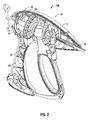
- Fig. 2 is a cut-away view of a handle assembly of the surgical instrument of Fig. 1 showing the internal components of the handle assembly.
- Surgical instrument 100 generally includes a handle assembly 10, an elongated shaft 20 extending from the handle assembly 10 and an end effector 30 disposed at a distal end 22 of the elongated shaft 20.
- surgical instrument 100 includes an integrated wireless camera configured to wirelessly transmit a signal to a wireless receiver 200.
- Wireless receiver 200 is configured to decouple the signal and feed the signal to a video display 300 to display the signal as a video image.
- a surgical instrument, e.g., surgical instrument 100, including an integrated wireless camera is particularly advantageous for use in minimally invasive as well as open surgical procedures.
- a surgical instrument 100 including an integrated wireless camera allows a surgeon as well as the surgical team to view a real-time image of the surgical site on a video display, without the need for additional incisions or larger incisions to allow camera to be inserted into the body.
- the wireless feature eliminates may of the difficulties associated with wired surgical cameras, e.g., limited maneuverability and the potential for tangling and/or disconnection.
- the fully integrated wireless camera is also advantageous in that it is disposed within the surgical instrument 100 without requiring the shaft 20 to be expanded to accommodate the components of the camera. As can be appreciated, this feature is particularly desirable for minimally invasive procedures, where access ports into the body are relatively small in diameter.
- surgical instrument 100 is shown as a surgical forceps 100, it is envisioned that the present disclosure be adaptable to numerous surgical instruments, thus providing a wireless integrated camera for use in various minimally invasive or open surgical procedures.
- surgical instrument 100 includes an elongated shaft 20 extending from handle assembly 10.
- elongated shaft 20 may be inserted through an access port (not shown), or opening in tissue, to position the end effector 30 within an internal body cavity.
- an image sensor assembly 40 is positioned toward a distal end 22 of elongated shaft 20.
- image sensor assembly 40 may be disposed at various positions toward the distal end 22 of elongated shaft 20, or may be disposed on the end effector 30, depending on the dimensions of the surgical instrument, the particular procedure to be performed and/or the desired field of view.
- the image sensor assembly 40 includes a lens 42 and an image sensor 44.
- the lens 42 is configured to project an optical image onto the image sensor 44.
- the lens 42 (or group of lenses) may be configured to focus, magnify, or otherwise modify the optical image projected onto the image sensor 44.
- the image sensor 44 is configured to convert the optical image into an electrical signal.
- the image sensor 44 may be a CCD image sensor, a CMOS image sensor, or any other suitable image sensor as is known in the art. Further, the image sensor 44 may be either a digital or an analog image sensor and, thus, may be configured to produce either a digital or an analog signal.
- the image sensor 44 is electrically coupled to an insulated wire, or bundle of wires 46 extending from the image sensor assembly 40 proximally through the shaft 20 and into the handle assembly 10 of surgical instrument 100.
- Bundle of wires 46 is configured to transmit the electrical signal produced by the image sensor 44 through the shaft 20 and to the control circuitry 50 ( Fig. 2 ) disposed within the handle assembly 10, as will be described in greater detail hereinbelow.
- Bundle of wires 46 is also configured to transfer power to the image sensor 44 from a battery 60 ( Fig. 2 ) disposed within the handle assembly 10.
- handle assembly 10 is shown with a portion of handle housing 12 removed to show the internal components of handle assembly 10.
- bundle of wires 46 extends proximally through the shaft 20 into the handle assembly 10, as mentioned above, coupling image sensor 44 to the control circuitry 50.
- Wire 56 provides power to the control circuitry 50 and ultimately connects to wire bundle 46 to power the image sensor 44 from the battery 60.
- Control circuitry 50 includes a processing component 52 and a wireless transmitter 54. More specifically, the signal produced by the image sensor 44 is communicated to the processing component 52, which processes the signal, e.g., converts the signal from analog to digital or digital to analog, or modulates the signal. In one embodiment, for example, the image sensor 44 communicates an analog signal to the processing component 52 which, in turn, synthesizes the signal with a carrier frequency, e.g., 2.4 GHz, and communicates the modulated signal to the wireless transmitter 54. Where the signal is a digital signal, the processing component 52 may be configured to first convert the signal to analog before modulating the signal and transmitting the signal to the wireless transmitter 54. In another embodiment, for example, the image sensor 44 communicates a digital signal to the processing component 52. The processing component 52 digitally modulates the signal and communicates the signal to the wireless transmitter 54. If the signal from the image sensor 44 is analog, the processing component may be configured to digitize the signal before communicating the signal to the wireless transmitter 54.
- the signal from the image sensor 44 is
- the wireless transmitter 54 is configured to wirelessly transmit, or broadcast the processed signal to the wireless receiver 200.
- the signal is analog, or converted to analog, and modulated with a carrier frequency, e.g. 2.4 GHz, by the processing component 52.
- the wireless transmitter 54 may be configured to broadcast the modulated analog signal to the wireless receiver 200.
- the wireless transmitter 54 may be configured according to a standard protocol, e.g., Bluetooth, Wi-Fi, or Zigbee.
- the wireless transmitter 54 may be a standard, off-the-shelf product.
- any other suitable wireless transmitter 54, standard or proprietary, may be used. As shown in Fig.
- an antenna 70 coupled to the wireless transmitter 54 via cable 72 may extend from the handle assembly 10 to facilitate transmission of the signal to the wireless receiver 200.
- antenna 70 is shown extending from handle assembly 10, it is also envisioned that antenna 70 be configured as a low profile antenna protruding minimally from handle assembly 10. Further, antenna 70 may be internally disposed within handle assembly 10.
- the wireless transmitter 54 and antenna 70 are configured to transmit the signal wirelessly to the wireless receiver 200.
- the wireless receiver 200 also include an antenna 210 to facilitate reception of the signal from the wireless transmitter 54.
- the wireless transmitter 54 and wireless receiver 200 have a working range suitable for use in an operating room or other surgical setting.
- the wireless transmitter 54 disposed within the surgical instrument 100 be capable of communication with the remote wireless receiver 200 throughout the entire surgical procedure, as the instrument 100 is maneuvered during the course of the procedure.
- the wireless receiver 200 may be a standard wireless receiver, e.g., a Bluetooth, Wi-Fi, Zigbee, or other off-the-shelf product according to the wireless transmitter 54, or alternatively, may be specifically configured according to the specifications of the non-standard, or proprietary wireless transmitter 54 disposed within the surgical instrument 100. In either embodiment, the wireless receiver 200 is configured to decouple, or demodulate, the signal and communicate the signal to the video monitor 300.
- the wireless receiver 200 may include standard electrical connections 215 such that the wireless receiver 200 may be coupled, e.g., via cables 230, to any standard video monitor 300.
- the video monitor 300 displays the signal as a video image.
- the battery, or battery pack 60 may be any standard battery as known in the art for powering the control circuitry 50 and the image sensor 44 of the integrated wireless camera. It is also envisioned, where the surgical instrument 100 is a battery powered instrument, that both the surgical instrument 100 and the integrated wireless camera be powered from the battery pack 60 such that the surgical instrument 100 may be fully wireless, allowing for uninhibited movement of the surgical instrument 100 during the surgical procedure. Further, the battery 60 may be replaceable and/or rechargeable.
Landscapes
- Health & Medical Sciences (AREA)
- Surgery (AREA)
- Life Sciences & Earth Sciences (AREA)
- Biomedical Technology (AREA)
- Nuclear Medicine, Radiotherapy & Molecular Imaging (AREA)
- Engineering & Computer Science (AREA)
- Ophthalmology & Optometry (AREA)
- Heart & Thoracic Surgery (AREA)
- Medical Informatics (AREA)
- Molecular Biology (AREA)
- Animal Behavior & Ethology (AREA)
- General Health & Medical Sciences (AREA)
- Public Health (AREA)
- Veterinary Medicine (AREA)
- Endoscopes (AREA)
Applications Claiming Priority (2)
| Application Number | Priority Date | Filing Date | Title |
|---|---|---|---|
| US31080310P | 2010-03-05 | 2010-03-05 | |
| US2518611A | 2011-02-11 | 2011-02-11 |
Publications (1)
| Publication Number | Publication Date |
|---|---|
| EP2363077A1 true EP2363077A1 (fr) | 2011-09-07 |
Family
ID=44082241
Family Applications (1)
| Application Number | Title | Priority Date | Filing Date |
|---|---|---|---|
| EP11250253A Withdrawn EP2363077A1 (fr) | 2010-03-05 | 2011-03-04 | Instrument chirurgical doté d'une caméra sans fil intégrée |
Country Status (1)
| Country | Link |
|---|---|
| EP (1) | EP2363077A1 (fr) |
Cited By (1)
| Publication number | Priority date | Publication date | Assignee | Title |
|---|---|---|---|---|
| CN111317529A (zh) * | 2014-04-17 | 2020-06-23 | 柯惠Lp公司 | 非接触式手术转接器的电接口 |
Citations (3)
| Publication number | Priority date | Publication date | Assignee | Title |
|---|---|---|---|---|
| US20080249370A1 (en) * | 2007-04-04 | 2008-10-09 | Dashiell Birnkrant | Video blade laryngoscope |
| US20090054803A1 (en) * | 2005-02-02 | 2009-02-26 | Vahid Saadat | Electrophysiology mapping and visualization system |
| US20090318758A1 (en) * | 2004-09-24 | 2009-12-24 | Vivid Medical, Inc. | Pluggable vision module and portable display for endoscopy |
-
2011
- 2011-03-04 EP EP11250253A patent/EP2363077A1/fr not_active Withdrawn
Patent Citations (3)
| Publication number | Priority date | Publication date | Assignee | Title |
|---|---|---|---|---|
| US20090318758A1 (en) * | 2004-09-24 | 2009-12-24 | Vivid Medical, Inc. | Pluggable vision module and portable display for endoscopy |
| US20090054803A1 (en) * | 2005-02-02 | 2009-02-26 | Vahid Saadat | Electrophysiology mapping and visualization system |
| US20080249370A1 (en) * | 2007-04-04 | 2008-10-09 | Dashiell Birnkrant | Video blade laryngoscope |
Cited By (2)
| Publication number | Priority date | Publication date | Assignee | Title |
|---|---|---|---|---|
| CN111317529A (zh) * | 2014-04-17 | 2020-06-23 | 柯惠Lp公司 | 非接触式手术转接器的电接口 |
| CN111317529B (zh) * | 2014-04-17 | 2024-03-08 | 柯惠Lp公司 | 非接触式手术转接器的电接口 |
Similar Documents
| Publication | Publication Date | Title |
|---|---|---|
| US20110218400A1 (en) | Surgical instrument with integrated wireless camera | |
| US9610133B2 (en) | Wireless laparoscopic camera | |
| US10912447B2 (en) | Laparoscope system | |
| US8182414B2 (en) | Endoscope system having retaining instrument | |
| US20120197078A1 (en) | Insufflation needle with integrated image sensor | |
| EP2522271B1 (fr) | Endoscope de caméra jumelé | |
| EP2449953B1 (fr) | Arthroscope à miroir | |
| EP2522270B1 (fr) | Endoscope vidéo tridimensionnel pivotant | |
| EP2363077A1 (fr) | Instrument chirurgical doté d'une caméra sans fil intégrée | |
| US20200281685A1 (en) | Functional imaging of surgical site with a tracked auxiliary camera | |
| EP2682043B1 (fr) | Ensemble de caméra chirurgicale | |
| AU2012230331B2 (en) | Laparoscope system | |
| HK1189788B (en) | Laparoscope system |
Legal Events
| Date | Code | Title | Description |
|---|---|---|---|
| PUAI | Public reference made under article 153(3) epc to a published international application that has entered the european phase |
Free format text: ORIGINAL CODE: 0009012 |
|
| AK | Designated contracting states |
Kind code of ref document: A1 Designated state(s): AL AT BE BG CH CY CZ DE DK EE ES FI FR GB GR HR HU IE IS IT LI LT LU LV MC MK MT NL NO PL PT RO RS SE SI SK SM TR |
|
| AX | Request for extension of the european patent |
Extension state: BA ME |
|
| 17P | Request for examination filed |
Effective date: 20120227 |
|
| RAP1 | Party data changed (applicant data changed or rights of an application transferred) |
Owner name: COVIDIEN LP |
|
| STAA | Information on the status of an ep patent application or granted ep patent |
Free format text: STATUS: THE APPLICATION HAS BEEN WITHDRAWN |
|
| 18W | Application withdrawn |
Effective date: 20130702 |