EP2363194B1 - Système d'élimination d'oxydes d'azote de gaz d'échappement - Google Patents
Système d'élimination d'oxydes d'azote de gaz d'échappement Download PDFInfo
- Publication number
- EP2363194B1 EP2363194B1 EP11154200A EP11154200A EP2363194B1 EP 2363194 B1 EP2363194 B1 EP 2363194B1 EP 11154200 A EP11154200 A EP 11154200A EP 11154200 A EP11154200 A EP 11154200A EP 2363194 B1 EP2363194 B1 EP 2363194B1
- Authority
- EP
- European Patent Office
- Prior art keywords
- ammonia
- catalyst layer
- exhaust gas
- catalyst
- nitrogen oxides
- Prior art date
- Legal status (The legal status is an assumption and is not a legal conclusion. Google has not performed a legal analysis and makes no representation as to the accuracy of the status listed.)
- Active
Links
Images

Classifications
-
- F—MECHANICAL ENGINEERING; LIGHTING; HEATING; WEAPONS; BLASTING
- F01—MACHINES OR ENGINES IN GENERAL; ENGINE PLANTS IN GENERAL; STEAM ENGINES
- F01N—GAS-FLOW SILENCERS OR EXHAUST APPARATUS FOR MACHINES OR ENGINES IN GENERAL; GAS-FLOW SILENCERS OR EXHAUST APPARATUS FOR INTERNAL-COMBUSTION ENGINES
- F01N3/00—Exhaust or silencing apparatus having means for purifying, rendering innocuous, or otherwise treating exhaust
- F01N3/08—Exhaust or silencing apparatus having means for purifying, rendering innocuous, or otherwise treating exhaust for rendering innocuous
- F01N3/10—Exhaust or silencing apparatus having means for purifying, rendering innocuous, or otherwise treating exhaust for rendering innocuous by thermal or catalytic conversion of noxious components of exhaust
- F01N3/18—Exhaust or silencing apparatus having means for purifying, rendering innocuous, or otherwise treating exhaust for rendering innocuous by thermal or catalytic conversion of noxious components of exhaust characterised by methods of operation; Control
- F01N3/20—Exhaust or silencing apparatus having means for purifying, rendering innocuous, or otherwise treating exhaust for rendering innocuous by thermal or catalytic conversion of noxious components of exhaust characterised by methods of operation; Control specially adapted for catalytic conversion
- F01N3/206—Adding periodically or continuously substances to exhaust gases for promoting purification, e.g. catalytic material in liquid form, NOx reducing agents
- F01N3/2066—Selective catalytic reduction [SCR]
-
- B—PERFORMING OPERATIONS; TRANSPORTING
- B01—PHYSICAL OR CHEMICAL PROCESSES OR APPARATUS IN GENERAL
- B01D—SEPARATION
- B01D53/00—Separation of gases or vapours; Recovering vapours of volatile solvents from gases; Chemical or biological purification of waste gases, e.g. engine exhaust gases, smoke, fumes, flue gases, aerosols
- B01D53/34—Chemical or biological purification of waste gases
- B01D53/74—General processes for purification of waste gases; Apparatus or devices specially adapted therefor
- B01D53/86—Catalytic processes
- B01D53/8621—Removing nitrogen compounds
- B01D53/8625—Nitrogen oxides
- B01D53/8628—Processes characterised by a specific catalyst
-
- B—PERFORMING OPERATIONS; TRANSPORTING
- B01—PHYSICAL OR CHEMICAL PROCESSES OR APPARATUS IN GENERAL
- B01J—CHEMICAL OR PHYSICAL PROCESSES, e.g. CATALYSIS OR COLLOID CHEMISTRY; THEIR RELEVANT APPARATUS
- B01J23/00—Catalysts comprising metals or metal oxides or hydroxides, not provided for in group B01J21/00
- B01J23/38—Catalysts comprising metals or metal oxides or hydroxides, not provided for in group B01J21/00 of noble metals
- B01J23/54—Catalysts comprising metals or metal oxides or hydroxides, not provided for in group B01J21/00 of noble metals combined with metals, oxides or hydroxides provided for in groups B01J23/02 - B01J23/36
- B01J23/56—Platinum group metals
- B01J23/64—Platinum group metals with arsenic, antimony, bismuth, vanadium, niobium, tantalum, polonium, chromium, molybdenum, tungsten, manganese, technetium or rhenium
- B01J23/652—Chromium, molybdenum or tungsten
- B01J23/6527—Tungsten
-
- F—MECHANICAL ENGINEERING; LIGHTING; HEATING; WEAPONS; BLASTING
- F01—MACHINES OR ENGINES IN GENERAL; ENGINE PLANTS IN GENERAL; STEAM ENGINES
- F01N—GAS-FLOW SILENCERS OR EXHAUST APPARATUS FOR MACHINES OR ENGINES IN GENERAL; GAS-FLOW SILENCERS OR EXHAUST APPARATUS FOR INTERNAL-COMBUSTION ENGINES
- F01N13/00—Exhaust or silencing apparatus characterised by constructional features
- F01N13/009—Exhaust or silencing apparatus characterised by constructional features having two or more separate purifying devices arranged in series
-
- B—PERFORMING OPERATIONS; TRANSPORTING
- B01—PHYSICAL OR CHEMICAL PROCESSES OR APPARATUS IN GENERAL
- B01D—SEPARATION
- B01D2251/00—Reactants
- B01D2251/20—Reductants
- B01D2251/206—Ammonium compounds
- B01D2251/2062—Ammonia
-
- B—PERFORMING OPERATIONS; TRANSPORTING
- B01—PHYSICAL OR CHEMICAL PROCESSES OR APPARATUS IN GENERAL
- B01D—SEPARATION
- B01D2255/00—Catalysts
- B01D2255/10—Noble metals or compounds thereof
- B01D2255/102—Platinum group metals
- B01D2255/1026—Ruthenium
-
- B—PERFORMING OPERATIONS; TRANSPORTING
- B01—PHYSICAL OR CHEMICAL PROCESSES OR APPARATUS IN GENERAL
- B01D—SEPARATION
- B01D2255/00—Catalysts
- B01D2255/20—Metals or compounds thereof
- B01D2255/207—Transition metals
- B01D2255/20776—Tungsten
-
- B—PERFORMING OPERATIONS; TRANSPORTING
- B01—PHYSICAL OR CHEMICAL PROCESSES OR APPARATUS IN GENERAL
- B01D—SEPARATION
- B01D2255/00—Catalysts
- B01D2255/90—Physical characteristics of catalysts
- B01D2255/902—Multilayered catalyst
- B01D2255/9022—Two layers
-
- B—PERFORMING OPERATIONS; TRANSPORTING
- B01—PHYSICAL OR CHEMICAL PROCESSES OR APPARATUS IN GENERAL
- B01D—SEPARATION
- B01D53/00—Separation of gases or vapours; Recovering vapours of volatile solvents from gases; Chemical or biological purification of waste gases, e.g. engine exhaust gases, smoke, fumes, flue gases, aerosols
- B01D53/34—Chemical or biological purification of waste gases
- B01D53/92—Chemical or biological purification of waste gases of engine exhaust gases
- B01D53/94—Chemical or biological purification of waste gases of engine exhaust gases by catalytic processes
- B01D53/9459—Removing one or more of nitrogen oxides, carbon monoxide, or hydrocarbons by multiple successive catalytic functions; systems with more than one different function, e.g. zone coated catalysts
- B01D53/9477—Removing one or more of nitrogen oxides, carbon monoxide, or hydrocarbons by multiple successive catalytic functions; systems with more than one different function, e.g. zone coated catalysts with catalysts positioned on separate bricks, e.g. exhaust systems
-
- B—PERFORMING OPERATIONS; TRANSPORTING
- B01—PHYSICAL OR CHEMICAL PROCESSES OR APPARATUS IN GENERAL
- B01J—CHEMICAL OR PHYSICAL PROCESSES, e.g. CATALYSIS OR COLLOID CHEMISTRY; THEIR RELEVANT APPARATUS
- B01J23/00—Catalysts comprising metals or metal oxides or hydroxides, not provided for in group B01J21/00
- B01J23/70—Catalysts comprising metals or metal oxides or hydroxides, not provided for in group B01J21/00 of the iron group metals or copper
- B01J23/89—Catalysts comprising metals or metal oxides or hydroxides, not provided for in group B01J21/00 of the iron group metals or copper combined with noble metals
- B01J23/8933—Catalysts comprising metals or metal oxides or hydroxides, not provided for in group B01J21/00 of the iron group metals or copper combined with noble metals also combined with metals, or metal oxides or hydroxides provided for in groups B01J23/02 - B01J23/36
- B01J23/8993—Catalysts comprising metals or metal oxides or hydroxides, not provided for in group B01J21/00 of the iron group metals or copper combined with noble metals also combined with metals, or metal oxides or hydroxides provided for in groups B01J23/02 - B01J23/36 with chromium, molybdenum or tungsten
-
- B—PERFORMING OPERATIONS; TRANSPORTING
- B01—PHYSICAL OR CHEMICAL PROCESSES OR APPARATUS IN GENERAL
- B01J—CHEMICAL OR PHYSICAL PROCESSES, e.g. CATALYSIS OR COLLOID CHEMISTRY; THEIR RELEVANT APPARATUS
- B01J27/00—Catalysts comprising the elements or compounds of halogens, sulfur, selenium, tellurium, phosphorus or nitrogen; Catalysts comprising carbon compounds
- B01J27/02—Sulfur, selenium or tellurium; Compounds thereof
- B01J27/053—Sulfates
-
- B—PERFORMING OPERATIONS; TRANSPORTING
- B01—PHYSICAL OR CHEMICAL PROCESSES OR APPARATUS IN GENERAL
- B01J—CHEMICAL OR PHYSICAL PROCESSES, e.g. CATALYSIS OR COLLOID CHEMISTRY; THEIR RELEVANT APPARATUS
- B01J35/00—Catalysts, in general, characterised by their form or physical properties
- B01J35/19—Catalysts containing parts with different compositions
-
- F—MECHANICAL ENGINEERING; LIGHTING; HEATING; WEAPONS; BLASTING
- F01—MACHINES OR ENGINES IN GENERAL; ENGINE PLANTS IN GENERAL; STEAM ENGINES
- F01N—GAS-FLOW SILENCERS OR EXHAUST APPARATUS FOR MACHINES OR ENGINES IN GENERAL; GAS-FLOW SILENCERS OR EXHAUST APPARATUS FOR INTERNAL-COMBUSTION ENGINES
- F01N2610/00—Adding substances to exhaust gases
- F01N2610/02—Adding substances to exhaust gases the substance being ammonia or urea
-
- Y—GENERAL TAGGING OF NEW TECHNOLOGICAL DEVELOPMENTS; GENERAL TAGGING OF CROSS-SECTIONAL TECHNOLOGIES SPANNING OVER SEVERAL SECTIONS OF THE IPC; TECHNICAL SUBJECTS COVERED BY FORMER USPC CROSS-REFERENCE ART COLLECTIONS [XRACs] AND DIGESTS
- Y02—TECHNOLOGIES OR APPLICATIONS FOR MITIGATION OR ADAPTATION AGAINST CLIMATE CHANGE
- Y02T—CLIMATE CHANGE MITIGATION TECHNOLOGIES RELATED TO TRANSPORTATION
- Y02T10/00—Road transport of goods or passengers
- Y02T10/10—Internal combustion engine [ICE] based vehicles
- Y02T10/12—Improving ICE efficiencies
Definitions
- the present invention relates to compositions and methods for treating exhaust gases and, in particular, to the removal of nitrogen oxides from exhaust gases.
- Denitrification or selective catalytic reduction (SCR) technology is commonly applied to combustion-derived flue gases for removal of nitrogen oxides.
- the denitrification reaction comprises the reaction of nitrogen oxide species in the gases, such as nitrogen oxide (NO) or nitrogen dioxide (NO 2 ), with a nitrogen containing reductant, such as ammonia or urea, resulting in the production of benign diatomic nitrogen (N 2 ) and water.
- nitrogen oxide species such as nitrogen oxide (NO) or nitrogen dioxide (NO 2 )
- a nitrogen containing reductant such as ammonia or urea
- catalyst responsible for conducting the reduction of nitrogen oxides is installed in the path of the flue gas flow and ammonia is injected upstream of the catalyst.
- the SCR system including the housing, catalyst bed, ammonia injection system controls, and mixing and/or flow control devices, is designed to remove a certain amount of NOx, while staying within a specified maximum level of NH 3 slip downstream of the catalyst, a maximum level of oxidation of SO 2 (sulfur dioxide) to SO 3 (sulfur trioxide), and a maximum pressure loss across the catalyst.
- Ammonia slip refers to the amount of ammonia present in the exhaust gas stream at the outlet of a catalyst.
- Sulfur dioxide oxidation is an undesirable side reaction promoted by SCR catalysts.
- the maximum limit for sulfur dioxide oxidation is specified to minimize the increase in sulfur trioxide downstream of the catalyst. Increased levels of sulfur trioxide can contribute to fouling of downstream equipment, can result in a visible plume at the exhaust stack of the combustion facility and increase particulate matter emissions.
- a maximum level of ammonia slip is specified to limit emissions of ammonia from the exhaust, and also to prevent the formation of ammonia salts, such as ammonium bisulfate that result from reaction between ammonia and other flue gas components such as sulfur trioxide. Ammonia salts can foul downstream equipment.
- the reaction is not thermodynamically limited at typical SCR temperatures, so if the molar ratio of NH 3 to NOx (or NH 3 /NOx) at the catalyst inlet is 1.0 and a sufficient amount of catalyst is present, the reduction of NOx and consumption of ammonia both approach 100%, and there is essentially no NOx and no ammonia slip at the outlet of the catalyst. If the molar ratio is less than 1.0 and a sufficient amount of catalyst is present, then the NOx reduction efficiency approaches the molar ratio and the ammonia slip approaches zero. If the molar ratio is greater than 1.0 and a sufficient amount of catalyst is present, then NOx reduction efficiency approaches 100% and all excess ammonia slips past the catalyst.
- compositions and methods for removing nitrogen oxides from exhaust gases operable to achieve high efficiencies while minimizing ammonia slip It would additionally be desirable to provide compositions and methods for removing nitrogen oxides from exhaust gases operable to achieve high efficiencies while minimizing ammonia slip and sulfur dioxide oxidation.
- the present invention provides compositions, systems, and methods for achieving high efficiencies of NOx removal from exhaust gases while minimizing ammonia slip and sulfur dioxide oxidation.
- the present invention provides a composition comprising a monolithic structural catalyst body comprising a uniform composition, the uniform composition comprising 50-99.9% by weight an inorganic oxide composition and a catalytically active metal functional group comprising ruthenium.
- the uniform chemical composition comprises at least 0.01 % by weight a catalytically active metal group comprising ruthenium.
- the uniform composition comprises from about 0.01% to about 5% by weight a catalytically active metal functional group comprising ruthenium.
- the uniform composition comprises greater than 1% to about 5% by weight a catalytically active metal functional group comprising ruthenium.
- the uniform composition comprises from about 0.01 % to 0.2% or from 0.6% to 0.9% by weight a catalytically active metal functional group comprising ruthenium. In one embodiment, the uniform composition comprises greater than about 5% by weight or less than about 0.01% by weight a catalytically active metal functional group comprising ruthenium.
- the catalytically active metal functional group of a structural catalyst body of the present invention further comprises metals in addition to ruthenium, including, but not limited to, vanadium pentoxide (V 2 O 5 ), tungsten oxide (WO 3 ), molybdenum oxide (MoO 3 ), promoted titanium (Ti) species, platinum group metals, gold, silver, iridium, cerium, other transition and noble metals, and/or mixtures thereof.
- the additional metals are part of the uniform composition used to form the structural catalyst body.
- catalytic material comprising the additional metals can be incorporated into the structural catalyst body as part of one or more coatings applied to a surface of the catalyst body.
- catalytic material comprising the additional metals can be incorporated into the structural catalyst body by impregnation.
- a monolithic structural catalyst body comprises an inert carrier on which a catalytically active metal functional group comprising ruthenium is disposed.
- the inert carrier in some embodiments, can be coated or impregnated with the catalytically active metal functional group comprising ruthenium.
- catalytic material comprising additional metals as provided herein can be disposed over the catalytic ruthenium composition by additional coatings or impregnations.
- a system for removing nitrogen oxides from an exhaust gas comprises an ammonia decomposition catalyst layer and a nitrogen oxide reduction catalyst layer downstream of the ammonia decomposition catalyst layer.
- Ammonia decomposition refers to the reaction of ammonia with oxygen to produce nitrogen, water, and/or nitrogen oxides.
- the ammonia decomposition catalyst layer is the first catalyst layer with which an exhaust gas comes into contact for removal of nitrogen oxides.
- an additional nitrogen oxide reduction catalyst layer is provided upstream of the ammonia decomposition layer.
- At least one addition point of an ammonia-containing compound upstream of the ammonia decomposition and/or nitrogen oxide reduction catalyst layers is also provided.
- An ammonia-containing compound comprises ammonia (NH 3 ) or any other chemical compound containing nitrogen that can decompose or react to form ammonia prior to contact with the catalyst or upon contact with the catalyst, including, but not limited to, urea [CO(NH 2 ) 2 ], cyanuric acid [2,4,6-trihydroxy-1,3,5-triazine], or isocyanic acid [HNCO].
- the ammonia-containing compound in some embodiments, comprises combinations of ammonia and other ammonia-containing compounds, and may be added in any form including aqueous mixtures.
- an ammonia-containing compound comprises excess ammonia from upstream selective non-catalytic reduction (SNCR) or selective auto-catalytic reduction (SACR) techniques and can be optionally mixed with one or more additional ammonia-containing compounds.
- a system for removing nitrogen oxides from an exhaust gas comprises a catalyst layer operable to effectuate both ammonia decomposition and nitrogen oxide reduction thereby rendering additional upstream or downstream catalyst layers optional or unnecessary.
- the catalyst layer comprises at least one monolithic structural catalyst body of the present invention.
- the present invention provides methods of removing nitrogen oxides from an exhaust gas.
- a method of removing nitrogen oxides from an exhaust gas comprises providing an ammonia decomposition catalyst layer, providing a nitrogen oxide reduction catalyst layer downstream of the ammonia decomposition catalyst layer, adding an ammonia-containing compound upstream of the catalyst layers in an amount not less than the stoichiometric equivalent of nitrogen oxides in the exhaust gas, and passing the exhaust gas through the ammonia decomposition catalyst layer and passing the exhaust gas through the nitrogen oxide reduction catalyst layer.
- the ammonia decomposition catalyst layer is the first catalyst layer with which an exhaust gas comes into contact for removal of nitrogen oxides.
- a method of removing nitrogen oxides from an exhaust gas comprises providing a first catalyst layer, catalytically decomposing ammonia in the exhaust gas and catalytically reducing nitrogen oxides in the exhaust gas by passing the exhaust gas through the first catalyst layer, wherein an ammonia-containing compound is added upstream of the first catalyst layer in an amount not less than the stoichiometric reaction equivalent of nitrogen oxides in the exhaust gas.
- the amount of ammonia exiting the first catalyst layer is less than about 5 ppmvd. In other embodiments, the amount of ammonia exiting the first catalyst layer is less than about 3 ppmvd. In a further embodiment, the amount of ammonia exiting the first catalyst layer is less than about 2 ppmvd.
- the method further comprises providing at least one additional nitrogen oxide reduction catalyst layer downstream of the first catalyst layer and flowing the exhaust gas through the at least one additional nitrogen oxide reduction catalyst layer.
- a method of removing nitrogen oxides from an exhaust gas comprises providing a first catalyst layer, adding an ammonia-containing compound to the exhaust gas upstream of the first catalyst layer in excess of the stoichiometric reaction equivalent of nitrogen oxides in the exhaust gas, flowing the exhaust gas through the first catalyst layer, selectively catalytically decomposing ammonia in excess of the stoichiometric reaction equivalent of the nitrogen oxides in the exhaust gas, and catalytically reducing the nitrogen oxides by reaction with ammonia not selectively catalytically decomposed.
- the amount of ammonia exiting the first catalyst layer is less than about 5 ppmvd.
- the amount of ammonia exiting the first catalyst layer is less than about 3 ppmvd. In one embodiment, the amount of ammonia exiting the first catalyst layer is less than about 2 ppmvd. In some embodiments, the method further comprises providing at least one additional nitrogen oxide reduction catalyst layer downstream of the first catalyst layer and flowing the exhaust gas through the at least one additional nitrogen oxide reduction catalyst layer.
- a method of removing nitrogen oxides from an exhaust gas comprises providing a first catalyst layer, adding an amount of ammonia-containing compound to the exhaust gas, flowing the exhaust gas through the first catalyst layer wherein the amount of ammonia-containing compound added produces a NH 3 /NOx molar ratio in excess of equivalence at one or more points in the first catalyst layer, selectively catalytically decomposing ammonia in excess of equivalence at the one or more points in the first catalyst layer, and catalytically reducing nitrogen oxides by reaction with ammonia not selectively catalytically decomposed.
- the amount of ammonia exiting the first catalyst layer is less than about 5 ppmvd.
- the amount of ammonia exiting the first catalyst layer is less than about 3 ppmvd. In one embodiment, the amount of ammonia exiting the first catalyst layer is less than about 2 ppmvd. In some embodiments, the method further comprises providing at least one additional nitrogen oxide reduction catalyst layer downstream of the first catalyst layer and flowing the exhaust gas through the at least one additional nitrogen oxide reduction catalyst layer.
- the amount of ammonia in the exhaust gas exiting the at least one additional catalyst layer is less than about 5 ppmvd, less than about 3 ppmvd, or less than about 2 ppmvd.
- Systems and methods for removing nitrogen oxides from exhaust gases can demonstrate nitrogen oxide removal efficiencies of at least 95%.
- systems and methods of the present invention can display a nitrogen oxide removal efficiency of at least 97%.
- systems and methods of the present invention can display a nitrogen oxide removal efficiency of at least 99%.
- an ammonia-containing compound is added in systems and methods of the present invention in an amount sufficient to produce a NH 3 /NOx molar ratio at the inlet of a catalyst layer having a value not less than equivalence (1.0).
- an ammonia-containing compound is added upstream of one or more catalyst layers to produce a NH 3 /NOx molar ratio in excess of equivalence at the inlet of the catalyst. In some embodiments, an ammonia-containing compound is added upstream of a catalyst layer to produce a NH 3 /NOx molar ratio at the inlet of the catalyst ranging from greater than 1.0 to about 2.0 or greater than 1.0 to about 1.5. In one embodiment, an ammonia-containing compound is added in an amount sufficient to produce a NH 3 /NOx molar ratio at the inlet of the catalyst ranging from about 0.95 to about 1.5 or from about 1.5 to about 2.0.
- an ammonia-containing compound is added in an amount sufficient to produce a NH 3 /NOx molar ratio ranging from about 1.0 to about 1.4. In a further embodiment, ammonia-containing compound is added in an amount sufficient to produce a NH 3 /NOx molar ratio at the inlet of the catalyst ranging from about 1.0 to about 1.2.
- an ammonia-containing compound is added to an exhaust gas in systems and methods of the present invention in an amount sufficient to produce a NH 3 /NOx molar ratio in excess of equivalence at one or more points within a catalyst layer.
- an ammonia-containing compound is added in an amount sufficient to produce a NH 3 /NOx molar ratio at one or more points within a catalyst layer ranging from greater than 1.0 to about 2.0 or from greater than 1.0 to about 1.5.
- an ammonia-containing compound is added in an amount sufficient to produce a NH 3 /NOx molar ratio at one or more points in a catalyst layer ranging from greater than 1.0 to about 1.3 or ranging from about 1.5 to about 2.0.
- a NH 3 /NOx molar ratio in excess of equivalence at one or more points within a catalyst layer can be achieved by the addition of an ammonia-containing compound to an exhaust gas in an amount less than or equal to the stoichiometric reaction equivalent of nitrogen oxides in the exhaust gas.
- a NH 3 /NOx molar ratio in excess of equivalence at one or more points within a catalyst layer can be achieved by the addition of an ammonia containing compound to an exhaust gas in an amount greater than the stoichiometric reaction equivalent of nitrogen oxides in the exhaust gas.
- exhaust gases treated with systems and methods described herein further comprise a sulfur trioxide content.
- Systems and methods of the present invention for removing nitrogen oxides from an exhaust gas result in no increase or substantially no increase of the sulfur trioxide content of the exhaust gas through the oxidation of sulfur dioxide.
- compositions, systems, and methods with increased efficiencies for the removal of nitrogen oxides in exhaust gases while maintaining minimal ammonia slip.
- the present invention provides compositions, systems, and methods for achieving high efficiencies of nitrogen oxide removal from exhaust gases while minimizing ammonia slip and sulfur dioxide oxidation.
- the present invention provides a composition comprising a monolithic structural catalyst body comprising a uniform composition, the uniform composition comprising 50-99.9% by weight an inorganic oxide composition and a catalytically active metal functional group comprising ruthenium.
- the uniform chemical composition comprises at least 0.01 % by weight a catalytically active metal group comprising ruthenium.
- the uniform composition comprises from about 0.01% to about 5% by weight a catalytically active metal functional group comprising ruthenium.
- the uniform composition comprises greater than 1% to about 5% by weight a catalytically active metal functional group comprising ruthenium.
- the uniform composition comprises from about 0.01% to 0.2% or from 0.6% to 0.9% by weight a catalytically active metal functional group comprising ruthenium. In one embodiment, the uniform composition comprises greater than about 5% by weight or less than about 0.01% by weight a catalytically active metal functional group comprising ruthenium.
- Monolithic structural catalyst bodies comprise an outer peripheral wall and a plurality of inner partition walls arranged within the outer peripheral wall.
- the inner partition walls define a cell opening size and delineate a plurality of flow channels, which extend longitudinally through the catalyst body.
- the outer peripheral and inner partition walls are formed from a uniform composition comprising 50-99.9% by weight an inorganic oxide composition and at least 0.01% by weight a catalytically active metal functional group comprising ruthenium.
- the uniform composition comprises from about 0.01% to about 5% by weight a catalytically active metal functional group comprising ruthenium.
- the uniform chemical composition comprises 70-95% by weight an inorganic oxide.
- Inorganic oxides suitable for use in monolithic structural catalyst bodies of the present invention include, but are not limited to, titania (TiO 2 ), alumina (Al 2 O 3 ), zirconia (ZrO 2 ), and/or mixtures thereof.
- the catalytically active metal functional group further comprises metals in addition to ruthenium, including, but not limited to, vanadium pentoxide (V 2 O 5 ), tungsten oxide (WO 3 ), molybdenum oxide (MoO 3 ), promoted titanium (Ti) species, platinum group metals, gold, silver, iridium, cerium, other transition and noble metals, and/or mixtures thereof.
- the additional metals are part of the uniform composition used to form the outer peripheral and inner partition walls.
- catalytic material comprising the additional metals can be coated or deposited onto at least one surface of the outer peripheral wall and/or inner partition walls.
- the depositing of catalytic material comprising additional metals in or on the inner partition walls can be accomplished by aqueous impregnation, dip coating, washcoating, chemical vapor deposition, spraying of droplets, or other suitable techniques including any surface pretreatment or post-treatments needed such as treatment with acid solution or thermal posttreatment.
- the catalytically active metal functional group when comprising additional metals, comprises 1-30% by weight of the structural catalyst body. In other embodiments, when comprising additional metals, the catalytically active metal functional group comprises 5-15% by weight or 10% to 20% by weight of the structural catalyst body.
- monolithic structural catalyst bodies of the present invention have a cell opening size of at least 5.5 mm. In another embodiment, structural catalyst bodies have a cell opening size of at least 6.0 mm.
- Structural catalyst bodies additionally comprise hydraulic diameter of at least 145 mm and a transverse compressive strength of at least 1.5 kg/cm 2 . In a further embodiment, the hydraulic diameter can range from 145 mm to 160 mm. In a still further embodiment the hydraulic diameter can range from 152 mm to 154 mm.
- monolithic structural catalyst bodies comprise an open frontal area greater than 80%.
- the structural catalyst body comprises a cell density of at least 2.05 cells/cm 2 .
- monolithic structural catalyst bodies of the present invention comprise a macroporosity greater than 0.05 cc/g in pores of diameter ranging from 600 to 5,000 Angstroms.
- the cell opening size can be at least 6.3 mm.
- a monolithic structural catalyst bodies comprises an open frontal area greater than or equal to 82%.
- a monolithic structural catalyst body of the present invention may be produced by mixing up to 50-99.9% by weight an inorganic oxide composition, or a precursor which yields an inorganic oxide composition and at least 0.01 % by weight a catalytically active metal functional group comprising ruthenium, or a precursor which yields a catalytically active metal functional group comprising ruthenium.
- the catalytically active metal functional group comprising ruthenium can be added directly to the inorganic oxide composition.
- the catalytically active metal functional group comprising ruthenium can be associated with support particles, such as titanium oxide and/or silicon oxide support particles, prior to mixing with the inorganic composition of the structural catalyst body.
- the support particles in some embodiments, are coated with the catalytically active metal functional group comprising ruthenium. In other embodiments, the support particles are impregnated with the catalytically active metal functional group comprising ruthenium. Once associated, the support particles and catalytically active metal functional group comprising ruthenium are mixed with the inorganic oxide composition of the structural catalyst body. As a result of the mixing, the support particles and associated catalytic material become imbedded and uniformly dispersed in the inorganic oxide composition.
- the catalytically active metal functional group may further comprise metals in addition to ruthenium including vanadium pentoxide (V 2 O 5 ), tungsten oxide (WO 3 ), molybdenum oxide (MoO 3 ), promoted (Ti) titanium species, platinum group metals, gold, silver, iridium, cerium, other transition and noble metals, and/or mixtures thereof.
- the inorganic oxide composition includes, but is not limited to, titania (TiO 2 ), alumina (Al 2 O 3 ), zirconia (ZrO 2 ), and/or mixtures thereof.
- the additional metals are part of the uniform composition which forms the structural catalyst body.
- the additional metals can be added directly to the inorganic oxide composition or can be associated with support particles in a manner consistent with that described for ruthenium above.
- the additional metals can be incorporated into the structural catalyst body as part of a coating applied to a surface of the catalyst body or impregnated throughout the catalyst body.
- the resulting catalytic mixture can be kneaded into a clay-like substance and subsequently extruded from an extrusion molding machine to form a honeycomb-like monolithic catalyst structure comprising the outer partition wall, inner partition walls and longitudinal flow channels.
- the extrusion formulation can comprise any number of peptizing agents, binding agents, extrusion aids, lubricants, plasticizers, reinforcement agents, and the like to assist in the extrusion process and/or generate the desired structural and pore properties for an intended application.
- materials that may be included in an extrusion formula include, but are not limited to, glass fibers or strands, silicon carbide fibers, inorganic acids (e.g. phosphoric acid, nitric acid, etc.) organic acids (e.g. acetic acid, citric acid, formic acid, etc.), salts of organic acids (e.g.
- ammonium formate, ammonium acetate, ammonium citrate, etc. cellulose compounds, starches, polyethylene oxide, stearic alcohols, alcohols, graphite, stearic acid, amines, oils, fats, and polymers.
- the extruded product may subsequently be dried or thermally treated.
- the extruded product may be subsequently deposited as described herein with additional catalyst material including metals such as a platinum group metal or other noble metal.
- the extrusion system may include extruder machines, a filter or screen, and an extrusion die.
- the filter or screen may be utilized to facilitate passage of the mixture through the die, for example to reduce clogging of the die, without removing filler, binders, and reinforcement aids that provide advantageous product properties.
- the extruded product may subsequently be dried or thermally treated.
- Additional energy is utilized in the mixing equipment to increase form-stability, and in the extrusion system to move the extrusion mixture through the extruder machines, filter or screen and die.
- lubricants and extrusion aids may be utilized in the starting composition for the catalyst body to minimize this additional energy.
- Other means of reducing additional energy known in the art, include maximizing mixer and extruder efficiency and minimizing wall friction in the screen and die.
- Figure 1 illustrates a monolithic structural catalyst body according to one embodiment of the present invention.
- the monolithic structural catalyst of Figure 1 displays a catalytically active outer peripheral wall 10 and a plurality of catalytically active inner partition walls 11.
- the inner partition walls 11 define a plurality of flow channels or cells 12 which extend longitudinally through the monolithic structural catalyst body for receiving exhaust gases.
- Monolithic structural catalyst bodies of the present invention are operable to perform catalytic decomposition of ammonia and/or catalytic reduction of nitrogen oxides in exhaust gases.
- monolithic structural catalyst bodies of the present invention selectively decompose ammonia in an exhaust gas.
- one method of increasing NOx reduction efficiency is to provide a NH 3 /NOx molar ratio in excess of equivalence.
- Providing a NH 3 /NOx molar ratio in excess of equivalence at the inlet of a conventional SCR catalyst leads to unacceptable ammonia slip at the outlet of the catalyst.
- providing a NH 3 /NOx molar ratio in excess of equivalence with structural catalyst of the present invention does not result in unacceptable slip at the outlet of the catalyst.
- a structural catalyst body of the present invention catalytically decomposes ammonia in excess of equivalence while performing catalytic reduction of nitrogen oxides in the exhaust gas.
- nitrogen oxide removal efficiencies are increased by using a NH 3 /NOx molar ratio in excess of equivalence without significant increases or no increase in ammonia slip at the outlet of the catalyst layer.
- monolithic structural catalyst bodies of the present invention substantially decrease and, in some cases, do not perform catalytic ammonia decomposition thereby allowing ammonia to be consumed in the catalytic reduction of nitrogen oxides. Such behavior permits monolithic structural catalyst bodies of the present invention to selectively decompose ammonia in an exhaust gas as a function of N H 3/NOx molar ratio.
- a system for removing nitrogen oxides from an exhaust gas comprises an ammonia decomposition catalyst layer and a nitrogen oxide reduction catalyst layer downstream of the ammonia decomposition layer.
- Ammonia decomposition layers of systems of the present invention comprise at least one monolithic structural catalyst body of the present invention as provided hereinabove. In some embodiments, ammonia decomposition layers comprise a plurality of monolithic structural catalyst bodies.
- an addition point of an ammonia-containing compound upstream of the ammonia decomposition and nitrogen oxide catalyst layers there is also provided at least one addition point of an ammonia-containing compound upstream of the ammonia decomposition and nitrogen oxide catalyst layers.
- the addition of an ammonia-containing compound upstream of one or more catalyst layers of the present invention provides a source of ammonia (NH 3 ) reductant for catalytic reduction of nitrogen oxides.
- the ammonia-containing compound is ammonia (NH 3 ).
- the ammonia-containing compound comprises any other chemical compound containing nitrogen that can decompose or react to form ammonia prior to contact with the catalyst or upon contact with the catalyst, including but not limited to urea [CO(NH 2 ) 2 ], cyanuric acid [2,4,6-trihydroxy-1,3,5-triazine], or isocyanic acid [HNCO].
- the ammonia-containing compound in some embodiments, comprises combinations of ammonia and other ammonia-containing compounds, and may be added in any form including aqueous mixtures.
- the ammonia-containing compound may comprise excess ammonia from upstream selective non-catalytic reduction (SNCR) or selective auto-catalytic reduction (SACR) techniques, optionally with additional ammonia-containing compound.
- an ammonia-containing compound is added upstream at one or more points, such as addition to the fuel prior to combustion, injection into a fuel combustion process, or injection downstream of the combustion process.
- Addition of the ammonia-containing compound downstream of the combustion process may be within a heat recovery section downstream of the combustion process, or may be injected downstream of a heat recovery section.
- the ammonia-containing compound may be added as a single stream or as multiple streams at any process location, such as an ammonia injection grid or injection lances.
- the rate of addition of any stream of ammonia-containing compound at any process location may be set to achieve low levels of heterogeneity in concentration of ammonia, nitrogen oxides, or molar ratio of ammonia to nitrogen oxides at the catalyst location.
- an ammonia-containing compound is added upstream of one or more catalyst layers to produce a NH 3 /NOx molar ratio in excess of reaction equivalence at the inlet of the catalyst. In some embodiments, an ammonia-containing compound is added upstream of a catalyst layer to produce a NH 3 /NOx molar ratio at the inlet of the catalyst ranging from greater than 1.0 to about 2.0 or greater than 1.0 to about 1.5. In one embodiment, an ammonia-containing compound is added in an amount sufficient to produce a NH 3 /NOx molar ratio at the inlet of the catalyst ranging from about 0.95 to about 1.5 or from about 1.5 to about 2.0.
- an ammonia-containing compound is added in an amount sufficient to produce a NH 3 /NOx molar ratio ranging from about 1.0 to about 1.4. In a further embodiment, ammonia-containing compound is added in an amount sufficient to produce a NH 3 /NOx molar ratio at the inlet of the catalyst ranging from about 1.0 to about 1.2.
- an ammonia-containing compound is added to an exhaust gas in systems and methods of the present invention in an amount sufficient to produce a NH 3 /NOx molar ratio in excess of equivalence at one or more points within a catalyst layer.
- an ammonia-containing compound is added in an amount sufficient to produce a NH 3 /NOx molar ratio at one or more points within a catalyst layer ranging from greater than 1.0 to about 2.0 or from greater than 1.0 to about 1.5.
- an ammonia-containing compound is added in an amount sufficient to produce a NH 3 /NOx molar ratio at one or more points in a catalyst layer ranging from greater than 1.0 to about 1.3 or ranging from about 1.5 to about 2.0.
- a system for removing nitrogen oxides from an exhaust gas further comprises an additional nitrogen oxide reduction catalyst layer upstream of the ammonia decomposition catalyst layer.
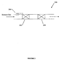
- Figure 2 illustrates a system for removing nitrogen oxides from an exhaust gas according to one embodiment of the present invention.
- the system (200) illustrated in Figure 2 comprises an ammonia decomposition catalyst layer (202) furthermost upstream of the exhaust gas flow and a nitrogen oxide reduction catalyst layer (204) downstream of the ammonia decomposition catalyst layer (202).
- Addition points (206) of an ammonia-containing compound are provided upstream of the ammonia decomposition catalyst layer (202) and the nitrogen oxide reduction catalyst layer (204).
- a system for removing nitrogen oxides from an exhaust gas comprises a catalyst layer operable to effectuate both catalytic ammonia decomposition and catalytic nitrogen oxide reduction, thereby rendering additional downstream and/or upstream catalytic layers optional.
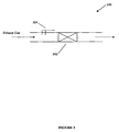
- Figure 3 illustrates such a system for removing nitrogen oxides from an exhaust gas.
- the system (300) illustrated in Figure 3 comprises a catalyst layer (302) operable to perform both catalytic ammonia decomposition and catalytic nitrogen oxide reduction. Addition points (304) for an ammonia-containing compound are located upstream of the catalyst layer (302).
- Systems for removing nitrogen oxides from an exhaust gas can display a nitrogen oxide removal efficiency of greater than 95%.
- systems for removing nitrogen oxides from an exhaust gas can demonstrate a nitrogen oxide removal efficiency of greater than 97%.
- systems for removing nitrogen oxides from an exhaust gas can demonstrate a nitrogen oxide removal efficiency greater than 99%.
- systems for removing nitrogen oxides from an exhaust gas in some embodiments, have an ammonia slip of less than 5 ppmvd. In other embodiments, systems for removing nitrogen oxides from an exhaust gas display an ammonia slip of less than 3 ppmvd. In a further embodiment, systems for removing nitrogen oxides from an exhaust gas demonstrate an ammonia slip of less than 2 ppmvd. In some embodiments, systems for removing nitrogen oxides from an exhaust gas provide minimal to no sulfur dioxide oxidation. In some embodiments, systems for removing nitrogen oxides from an exhaust gas can comprise mercury oxidation functionality.
- a method of removing nitrogen oxides from an exhaust gas comprises providing an ammonia decomposition catalyst layer, providing a nitrogen oxide reduction catalyst layer downstream of the ammonia decomposition catalyst layer, adding an ammonia-containing compound upstream of the ammonia decomposition catalyst layer and nitrogen oxide reduction catalyst layer in an amount not less than the stoichiometric reaction equivalent of nitrogen oxides in the exhaust gas, and passing the exhaust gas through the ammonia decomposition catalyst layer and through the nitrogen oxide reduction catalyst layer.
- at least one additional nitrogen oxide reduction catalyst layer can be placed upstream of the ammonia decomposition catalyst layer.
- An ammonia decomposition catalyst layer in embodiments of methods the present invention, comprises at least one monolithic structural catalyst body as described hereinabove. In some embodiments, the ammonia decomposition catalyst layer comprises a plurality of monolithic structural catalyst bodies of the present invention.
- a method of removing nitrogen oxides from an exhaust gas comprises providing a first catalyst layer, catalytically decomposing ammonia in the exhaust gas and catalytically reducing nitrogen oxides in the exhaust gas by passing the exhaust gas through the first catalyst layer, wherein an ammonia containing compound is added upstream of the first catalyst layer in an amount not less than the stoichiometric reaction equivalent of nitrogen oxides in the exhaust gas.
- the first catalyst layer comprises at least one monolithic structural catalyst body of the present invention.
- the first catalyst layer comprises a plurality of monolithic structural catalyst bodies of the present invention.
- a method further comprises providing at least one additional nitrogen oxide reduction catalyst layer downstream of the first catalyst layer and flowing the exhaust gas through the at least one additional nitrogen oxide reduction catalyst layer.
- a method of removing nitrogen oxides from an exhaust gas comprises providing a first catalyst layer, adding an ammonia-containing compound to the exhaust gas upstream of the first catalyst layer in excess of the stoichiometric reaction equivalent of nitrogen oxides in the exhaust gas, flowing the exhaust gas through the first catalyst layer, selectively catalytically decomposing ammonia in excess of the stoichiometric reaction equivalent of nitrogen oxides in the exhaust gas, and catalytically reducing the nitrogen oxides by reaction with ammonia not selectively catalytically decomposed.
- the amount of ammonia exiting the first catalyst layer is less than about 5 ppmvd. In other embodiments, the amount of ammonia exiting the first catalyst layer is less than about 3 ppmvd. In a further embodiment, the amount of ammonia exiting the first catalyst layer is less than about 2 ppmvd. Moreover, in some embodiments, a method further comprises providing at least one additional nitrogen oxide reduction catalyst layer downstream of the first catalyst layer and flowing the exhaust gas through the at least one additional nitrogen oxide reduction catalyst layer.
- a method of removing nitrogen oxides from an exhaust gas comprises providing a first catalyst layer, adding an amount of ammonia-containing compound to the exhaust gas, flowing the exhaust gas through the first catalyst layer wherein the amount of ammonia-containing compound added produces a NH 3 /NOx molar ratio in excess of equivalence at one or more points in the first catalyst layer, selectively catalytically decomposing ammonia in excess of equivalence at the one or more points in the first catalyst layer, and catalytically reducing nitrogen oxides by reaction with ammonia not selectively catalytically decomposed.
- the amount of ammonia exiting the first catalyst layer is less than about 5 ppmvd.
- the amount of ammonia exiting the first catalyst layer is less than about 3 ppmvd. In one embodiment, the amount of ammonia exiting the first catalyst layer is less than about 2 ppmvd. In a further embodiment, a method further comprises providing at least one additional nitrogen oxide reduction catalyst layer downstream of the first catalyst layer and flowing the exhaust gas through the at least one additional nitrogen oxide reduction catalyst layer.
- the amount of ammonia in the exhaust gas exiting the at least one additional catalyst layer is less than about 5 ppmvd, less than about 3 ppmvd, or less than about 2 ppmvd.
- an ammonia-containing compound is added upstream of the catalyst layer at one or more points, such as addition to the fuel prior to combustion, injection into a fuel combustion process, or injection downstream of the combustion process.
- the addition of the ammonia-containing compound downstream of the combustion process may be within a heat recovery section downstream of the combustion process or may be injected downstream of a heat recovery section.
- the ammonia-containing compound may be added as a single stream or as multiple streams at any process location, such as an ammonia injection grid or injection lances.
- the rate of addition of any stream of ammonia-containing compound at any process location may be set to achieve low levels of heterogeneity in concentration of ammonia, nitrogen oxides, or molar ratio of ammonia to nitrogen oxides at the catalyst location.
- the amount of ammonia added to an exhaust gas to achieve a desired NH 3 /NOx molar ratio can be determined by monitoring the nitrogen oxide concentration in the exhaust gas at one or a plurality of points in the flow path of the exhaust gas.
- the nitrogen oxide content of an exhaust gas is measured upstream of a catalyst layer and ammonia is added to achieve a desired NH 3 /NOx molar ratio based on the result of the measurement.
- the nitrogen oxide content of an exhaust gas is measured downstream of a catalyst layer, and ammonia is added to achieve a desired NH 3 /NOx molar ratio based on the result of the measurement.
- an ammonia-containing compound is added in systems and methods of the present invention in an amount sufficient to produce a NH 3 /NOx molar ratio at the inlet of a catalyst layer having a value not less than equivalence (1.0).
- an ammonia-containing compound is added upstream of one or more catalyst layers to produce a NH 3 /NOx molar ratio in excess of reaction equivalence at the inlet of the catalyst. In some embodiments, an ammonia-containing compound is added upstream of a catalyst layer to produce a NH 3 /NOx molar ratio at the inlet of the catalyst ranging from greater than 1.0 to about 2.0 or greater than 1.0 to about 1.5. In one embodiment, an ammonia-containing compound is added in an amount sufficient to produce a NH 3 /NOx molar ratio at the inlet of the catalyst ranging from about 0.95 to about 1.5 or from about 1.5 to about 2.0.
- an ammonia-containing compound is added in an amount sufficient to produce a NH 3 /NOx molar ratio ranging from about 1.0 to about 1.4. In a further embodiment, ammonia-containing compound is added in an amount sufficient to produce a NH 3 /NOx molar ratio at the inlet of the catalyst ranging from about 1.0 to about 1.2.
- an ammonia-containing compound is added to an exhaust gas in systems and methods of the present invention in an amount sufficient to produce a NH 3 /NOx molar ratio in excess of equivalence at one or more points within a catalyst layer.
- an ammonia-containing compound is added in an amount sufficient to produce a NH 3 /NOx molar ratio at one or more points within a catalyst layer ranging from greater than 1.0 to about 2.0 or from greater than 1.0 to about 1.5.
- an ammonia-containing compound is added in an amount sufficient to produce a NH 3 /NOx molar ratio at one or more points in a catalyst layer ranging from greater than 1.0 to about 1.3 or ranging from about 1.5 to about 2.0.
- a NH 3 /NOx molar ratio in excess of equivalence at one or more points within a catalyst layer can be achieved by the addition of an ammonia-containing compound to an exhaust gas in an amount less than or equal to the stoichiometric reaction equivalent of nitrogen oxides in the exhaust gas.
- a NH 3 /NOx molar ratio in excess of equivalence at one or more points within a catalyst layer can be achieved by the addition of an ammonia containing compound to an exhaust gas in an amount greater than the stoichiometric reaction equivalent of nitrogen oxides in the exhaust gas.
- Selective catalytic decomposition of ammonia in excess of the stoichiometric equivalence of the nitrogen oxides in the exhaust gas reduces ammonia slip at the exit of the catalyst layer.
- the selective catalytic decomposition of ammonia in excess of the stoichiometric equivalence in some embodiments of methods of the present invention, permits the use of excess ammonia to increase the efficiency of nitrogen oxide reduction without the concomitant increase in ammonia slip at the exit of a catalyst layer.
- Catalyst layers of systems and methods of the present invention comprise at least one monolithic structural catalyst body as described herein.
- catalyst layers of systems and methods of the present invention comprise a plurality of monolithic structural catalyst bodies operable to effectuate ammonia decomposition and/or selective catalytic reduction of nitrogen oxides.
- Systems and methods for removing nitrogen oxides from exhaust gases can demonstrate nitrogen oxide removal efficiencies of at least 95%.
- systems and methods of the present invention can display a nitrogen oxide removal efficiency of at least 97%.
- systems and methods of the present invention can display a nitrogen oxide removal efficiency of at least 99%.
- exhaust gases treated with systems and methods described herein further comprise a sulfur trioxide content.
- Systems and methods of the present invention for removing nitrogen oxides from an exhaust gas result in no increase or substantially no increase of the sulfur trioxide content of the exhaust gas through the oxidation of sulfur dioxide.
- methods for removing nitrogen oxides from an exhaust gas can comprise mercury oxidation functionality.
- a honeycomb-like monolithic structural catalyst body of the present invention was produced in lab-scale manufacturing facilities according to methods provided hereinabove, including the mixing of ingredients, extrusion to a honeycomb shape, drying, and calcination.
- the catalytic body displayed a catalyst composition comprising an inorganic oxide content of 85% titania (TiO 2 ), 9% catalytically active metals composition comprising tungsten trioxide (WO 3 ), 0.3% ruthenium, and 5.7% other components comprising SiO 2 , CaO, Al 2 O 3 , Fe 2 O 3 , SO 4 , and minor species.
- the flow channels enclosed by the inner partition walls and outer peripheral wall were nominally square in cross-sectional profile with a cell size of 6.3 mm.
- the pitch of monolithic catalyst body was 7.1 mm.
- the monolithic structural catalyst was subsequently tested for the selective catalytic reduction of nitrogen oxides in a gas.
- Performance testing of the structural catalyst for the selective reduction of nitrogen oxides was conducted in accordance with accepted industry standards.
- the catalytic performance was measured in a micro-reactor at a temperature of 380°C in a simulated gas stream consisting of approximately 3.5% oxygen on a dry basis, 10% water vapor, 350 ppmvd nitrogen monoxide, 300-475 ppmvd ammonia, and balance N 2 .
- Concentrations of ammonia, nitrogen oxides, and sulfur trioxide were measured at points along the structural catalyst including at the inlet and the outlet.
- the catalytic performance was thereby measured as a function of residence time of gas along the length of the catalyst layer, such residence time being expressed as the reciprocal of area velocity which ranged from zero at the catalyst inlet to approximately 0.06 hrs-m 2 /Nm 3 at the catalyst outlet where m 2 is the geometric surface area of the exposed surfaces of the catalyst in contact with the gas flow, and where Nm 3 is normal cubic meters of gas flow per hour.
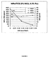
- Figure 4 illustrates the results of the testing.
- the monolithic structural catalyst body demonstrated selective catalytic ammonia decomposition and catalytic nitrogen oxide reduction.
- the slope of ammonia concentration from 0 to about 0.03 hrs-m 2 /Nm 3 exceeded the slope ofNOx concentration for the same residence time period indicating that ammonia in excess of the stoichiometric reaction equivalent of the nitrogen oxides was being selectively catalytically decomposed.
- the NH 3 /NOx molar ratio at the inlet of the monolithic structural catalyst body was about 1.2.
- the slope of the ammonia concentration flattened to match the slope of the NOx concentration.
- the selective catalytic decomposition of the ammonia in excess of the stoichiometric reaction equivalent of the nitrogen oxides in the exhaust gas coupled with the 1:1 reaction with the nitrogen oxides in the exhaust gas allowed excess ammonia to be supplied in the catalytic reduction of nitrogen oxides without the concomitant release of unacceptable ammonia levels at the outlet of the monolithic structural catalyst body.
- the monolithic structural catalyst body demonstrated substantially no sulfur dioxide oxidation when catalytically removing nitrogen oxides from the exhaust gas. As shown in Figure 4 , sulfur trioxide concentration remained steady indicating minimal to no oxidation of sulfur dioxide in the exhaust gas by the monolithic structural catalyst body.
Landscapes
- Engineering & Computer Science (AREA)
- Chemical & Material Sciences (AREA)
- Chemical Kinetics & Catalysis (AREA)
- Environmental & Geological Engineering (AREA)
- Health & Medical Sciences (AREA)
- General Engineering & Computer Science (AREA)
- Mechanical Engineering (AREA)
- Combustion & Propulsion (AREA)
- Analytical Chemistry (AREA)
- Oil, Petroleum & Natural Gas (AREA)
- General Chemical & Material Sciences (AREA)
- Biomedical Technology (AREA)
- Materials Engineering (AREA)
- Organic Chemistry (AREA)
- Toxicology (AREA)
- Catalysts (AREA)
- Exhaust Gas Treatment By Means Of Catalyst (AREA)
- Treating Waste Gases (AREA)
- Materials For Photolithography (AREA)
- Respiratory Apparatuses And Protective Means (AREA)
- Exhaust Gas After Treatment (AREA)
- Glass Compositions (AREA)
Claims (14)
- Système d'élimination d'oxydes d'azote d'un gaz d'échappement, comprenant :une première couche catalytique (302) comprenant au moins un corps catalytique structurel monolithique formé à partir d'une composition uniforme comprenant 50 à 99,9 % en poids d'une composition d'oxyde inorganique et d'un groupement fonctionnel métallique catalytiquement actif comprenant du ruthénium dispersé dans la composition d'oxyde inorganique ;un ou plusieurs points d'addition (304) pour un composé contenant de l'ammoniac, situés en amont de la couche catalytique ;ledit système étant à même d'effectuer un procédé dans lequel :• du gaz d'échappement s'écoule à travers la première couche catalytique (302), la quantité ajoutée de composé contenant de l'ammoniac produisant un rapport molaire NH3/NOx en excès d'équivalence en un ou plusieurs points de la première couche catalytique (302) ;et, dans la première couche catalytique (302), le procédé consistant à :• décomposer sélectivement par voie catalytique l'ammoniac en excès d'équivalence au niveau des un ou plusieurs points de la première couche catalytique (302) ; et• réduire par voie catalytique les oxydes d'azote par réaction avec de l'ammonïac non sélectivement décomposée par voie catalytique.
- Système selon la revendication 1, dans lequel le corps catalytique structurel monolithique comprend le ruthénium en quantité :• d'au moins 0,01 % en poids ;• variant de 0,01 % en poids à 0,2 % en poids ;• variant de 0,6 % en poids à 0,9 % en poids ;• supérieure à 1 % en poids à 5 % en poids ; ou• supérieure à 5 % en poids.
- Système selon la revendication 2, dans lequel le groupement fonctionnel métallique catalytiquement actif comprend par ailleurs du pentoxyde de vanadium (V2O5), de l'oxyde de tungstène (WO3), de l'oxyde de molybdène (MoO3), des espèces de titane (Ti) promues, des métaux du groupe du platine, de l'or, de l'argent, de l'iridium, du cérium, d'autres métaux de transition et métaux nobles et/ou leurs mélanges.
- Système selon la revendication 1, dans lequel le composé contenant de l'ammoniac comprend l'ammoniac ou un composé qui se décompose pour former de l'ammoniac avant ou au cours d'un contact avec le corps catalytique structurel monolithique.
- Système selon la revendication 1, dans lequel les corps catalytiques structurels monolithiques comprennent une paroi périphérique externe et une pluralité de cloisons internes.
- Système selon la revendication 1, dans lequel les corps catalytiques structurel monolithiques ont une surface frontale ouverte supérieure à 80 %.
- Système selon la revendication 1, dans lequel les corps catalytiques structurel monolithiques ont une surface frontale ouverte supérieure à 82 %.
- Système selon la revendication 1, dans lequel les corps catalytiques structurel monolithiques ont une densité cellulaire d'au moins 2,5 cellules/cm2.
- Système selon la revendication 1, dans lequel les corps catalytiques structurels monolithiques ont un diamètre hydraulique supérieur ou égal à 100 mm.
- Système selon la revendication 1, dans lequel le corps catalytique structurel monolithique est imprégné d'un matériau catalytique supplémentaire.
- Système selon la revendication 1, dans lequel le corps catalytique structurel monolithique est revêtu par lavage d'un matériau catalytique supplémentaire.
- Système selon la revendication 1, dans lequel le corps catalytique structurel monolithique est revêtu par immersion d'un matériau catalytique supplémentaire.
- Système selon l'une quelconque des revendications 10 à 12, dans lequel le groupement fonctionnel métallique catalytiquement actif comprend du pentoxyde de vanadium (V2O5), de l'oxyde de tungstène (WO3), de l' oxyde de molybdène (MoO3), des espèces de titane (Ti) promues, des métaux du groupe du platine, de l'or, de l'argent, de l'iridium, du cérium, d'autres métaux de transition et métaux nobles et/ou leurs mélanges.
- Corps catalytique structurel monolithique formé à partir d'une composition uniforme comprenant 50 à 99,9 % en poids d'une composition d'oxyde inorganique et d'un groupement fonctionnel métallique catalytiquement actif comprenant du ruthénium dispersé dans la composition d'oxyde inorganique, pour un usage dans le système et ayant les caractéristiques de l'une quelconque des revendications 2 à 13.
Applications Claiming Priority (2)
| Application Number | Priority Date | Filing Date | Title |
|---|---|---|---|
| US83461406P | 2006-08-01 | 2006-08-01 | |
| EP07810965A EP2054139B1 (fr) | 2006-08-01 | 2007-08-01 | Méthode de traitement des gaz d'échappement |
Related Parent Applications (1)
| Application Number | Title | Priority Date | Filing Date |
|---|---|---|---|
| EP07810965.9 Division | 2007-08-01 |
Publications (2)
| Publication Number | Publication Date |
|---|---|
| EP2363194A1 EP2363194A1 (fr) | 2011-09-07 |
| EP2363194B1 true EP2363194B1 (fr) | 2012-10-31 |
Family
ID=38769965
Family Applications (2)
| Application Number | Title | Priority Date | Filing Date |
|---|---|---|---|
| EP07810965A Active EP2054139B1 (fr) | 2006-08-01 | 2007-08-01 | Méthode de traitement des gaz d'échappement |
| EP11154200A Active EP2363194B1 (fr) | 2006-08-01 | 2007-08-01 | Système d'élimination d'oxydes d'azote de gaz d'échappement |
Family Applications Before (1)
| Application Number | Title | Priority Date | Filing Date |
|---|---|---|---|
| EP07810965A Active EP2054139B1 (fr) | 2006-08-01 | 2007-08-01 | Méthode de traitement des gaz d'échappement |
Country Status (8)
| Country | Link |
|---|---|
| US (3) | US7658898B2 (fr) |
| EP (2) | EP2054139B1 (fr) |
| JP (1) | JP2009545437A (fr) |
| AT (1) | ATE498452T1 (fr) |
| CA (1) | CA2659740C (fr) |
| DE (1) | DE602007012553D1 (fr) |
| DK (2) | DK2054139T3 (fr) |
| WO (1) | WO2008016627A1 (fr) |
Families Citing this family (24)
| Publication number | Priority date | Publication date | Assignee | Title |
|---|---|---|---|---|
| US7658898B2 (en) * | 2006-08-01 | 2010-02-09 | Cormetech, Inc. | Compositions and methods for treating exhaust gases |
| US7901647B2 (en) * | 2008-04-07 | 2011-03-08 | Babcock & Wilcox Power Generation Group, Inc. | Enhancement of conventional SCR and SNCR processes with ammonia destruction catalyst |
| US8505278B2 (en) * | 2009-04-30 | 2013-08-13 | Cummins Ip, Inc. | Engine system properties controller |
| DE102008046994B4 (de) * | 2008-09-12 | 2015-02-12 | Süd-Chemie Ip Gmbh & Co. Kg | Harnstoff-Hydrolyse-Katalysator |
| US8524185B2 (en) * | 2008-11-03 | 2013-09-03 | Basf Corporation | Integrated SCR and AMOx catalyst systems |
| JP5244550B2 (ja) * | 2008-11-14 | 2013-07-24 | バブコック日立株式会社 | 排ガス処理装置 |
| US8356471B2 (en) * | 2008-12-05 | 2013-01-22 | Cummins Ip, Inc. | Apparatus, system, and method for controlling reductant dosing in an SCR catalyst system |
| US8491845B2 (en) * | 2009-09-10 | 2013-07-23 | Cummins Ip, Inc. | Low temperature selective catalytic reduction catalyst and associated systems and methods |
| JP4920752B2 (ja) * | 2010-01-05 | 2012-04-18 | 日本碍子株式会社 | ハニカム構造体 |
| US8733083B2 (en) * | 2010-04-26 | 2014-05-27 | Cummins Filtration Ip, Inc. | SCR catalyst ammonia surface coverage estimation and control |
| EP2579963A1 (fr) | 2010-06-09 | 2013-04-17 | Cormetech, Inc. | Dispositif et procédés de traitement des gaz d'échappement |
| EP2603320B1 (fr) | 2010-08-09 | 2016-02-10 | Cormetech, Inc. | Structure catalytique |
| US20120282564A1 (en) * | 2011-05-03 | 2012-11-08 | Electric Power Research Institute, Inc. | METHODS FOR REDUCING NOx IN SCR FOSSIL-FUEL FIRED BOILERS |
| WO2013016674A2 (fr) | 2011-07-27 | 2013-01-31 | Cormetech, Inc. | Appareil de combustion et ses applications |
| US9101877B2 (en) * | 2012-02-13 | 2015-08-11 | Siemens Energy, Inc. | Selective catalytic reduction system and process for control of NOx emissions in a sulfur-containing gas stream |
| JP2015524743A (ja) * | 2012-07-26 | 2015-08-27 | コーメテック, インコーポレイテッド | ハニカム触媒アッセンブリーおよびその応用 |
| US8815193B1 (en) | 2013-04-29 | 2014-08-26 | Southwest Research Institute | Selective non-catalytic reduction for NOx removal |
| JP2016538161A (ja) | 2013-11-27 | 2016-12-08 | コーニング インコーポレイテッド | 基板の改善された製造のための組成 |
| CN105879614A (zh) * | 2014-12-24 | 2016-08-24 | 苏州超等环保科技有限公司 | 一种超声波加等离子加高压电场喷涂废气净化工艺 |
| US20180058698A1 (en) * | 2016-08-23 | 2018-03-01 | General Electric Technology Gmbh | Tempered Ammonia Injection For Gas Turbine Selective Catalyst Reduction System |
| GB2555695A (en) * | 2016-08-25 | 2018-05-09 | Johnson Matthey Plc | Reduced sulfation impact on CU-SCRS |
| DE102018113502A1 (de) * | 2018-06-06 | 2019-12-12 | Clariant International Ltd | Wabenkatalysator, Verfahren zur Oxidation von Kohlenmonoxid und organischen Luftschadstoffen mit dem Wabenkatalysator sowie Verwendung des Wabenkatalysators |
| CN117345381B (zh) | 2019-05-09 | 2026-03-17 | 康明斯排放处理公司 | 用于分流式紧密联接催化剂的阀门装置 |
| JP2023161201A (ja) | 2022-04-25 | 2023-11-07 | 三菱重工業株式会社 | 排ガス処理装置、燃焼設備及び排ガス処理方法 |
Family Cites Families (56)
| Publication number | Priority date | Publication date | Assignee | Title |
|---|---|---|---|---|
| US3441381A (en) | 1965-06-22 | 1969-04-29 | Engelhard Ind Inc | Apparatus for purifying exhaust gases of an internal combustion engine |
| US3784675A (en) * | 1971-08-02 | 1974-01-08 | Gulf Research Development Co | Process for reducing the content of nitrogen oxides in the exhaust gases from internal combustion engines |
| US3809743A (en) * | 1972-01-07 | 1974-05-07 | Monsanto Co | Process for treating automotive exhaust |
| US4071324A (en) * | 1976-06-01 | 1978-01-31 | Luther James Reid | Chemical reactor |
| JPS5824174B2 (ja) * | 1977-08-31 | 1983-05-19 | 三菱重工業株式会社 | 排ガス処理法 |
| US4335023A (en) * | 1980-01-24 | 1982-06-15 | Engelhard Corporation | Monolithic catalyst member and support therefor |
| JPS56113349A (en) | 1980-02-08 | 1981-09-07 | Hakko Denki Seisakusho:Kk | Sheathed heater with catalytic body |
| US4472358A (en) * | 1982-05-27 | 1984-09-18 | Georgia Tech Research Institute | Packing for fluidized bed reactors |
| JPS6124168A (ja) | 1984-07-13 | 1986-02-01 | Mitsubishi Electric Corp | 溶融炭酸塩形燃料電池装置 |
| DE3532577A1 (de) * | 1985-09-12 | 1987-03-12 | Didier Werke Ag | Kassette fuer katalysatorplatten |
| DE3632322A1 (de) * | 1986-09-19 | 1988-03-24 | Otto Feuerfest Gmbh | Katalysatorformkoerper sowie verfahren und vorrichtung zu seiner herstellung |
| US4904633A (en) * | 1986-12-18 | 1990-02-27 | Nippon Shokubai Kagaku Kogyo Co., Ltd. | Catalyst for purifying exhaust gas and method for production thereof |
| JPH01119341A (ja) * | 1987-10-30 | 1989-05-11 | Nkk Corp | アンモニア分解用触媒 |
| JPH01306710A (ja) | 1988-06-06 | 1989-12-11 | Toyota Central Res & Dev Lab Inc | 触媒燃焼装置 |
| US4929586A (en) | 1988-06-09 | 1990-05-29 | W. R. Grace & Co.-Conn. | Catalysts for selective catalytic reduction DeNOx technology |
| US5076908A (en) * | 1989-07-19 | 1991-12-31 | Chevron Research & Technology Company | Method and apparatus for an on-stream particle replacement system for countercurrent contact of a gas and liquid feed stream with a packed bed |
| US5916529A (en) * | 1989-07-19 | 1999-06-29 | Chevron U.S.A. Inc | Multistage moving-bed hydroprocessing reactor with separate catalyst addition and withdrawal systems for each stage, and method for hydroprocessing a hydrocarbon feed stream |
| US5102634A (en) * | 1990-01-17 | 1992-04-07 | Nippon Shokubai Kagaky Kogyo Co., Ltd. | Method for purifying exhaust gas and apparatus |
| JP3076421B2 (ja) * | 1991-10-08 | 2000-08-14 | バブコック日立株式会社 | 二酸化硫黄の酸化を抑制した脱硝触媒およびその製造方法 |
| JP3321190B2 (ja) * | 1991-11-27 | 2002-09-03 | バブコック日立株式会社 | 脱硝機能を備えたアンモニア分解触媒および排ガス浄化方法 |
| JP2659504B2 (ja) * | 1991-12-26 | 1997-09-30 | 大阪瓦斯株式会社 | 触媒燃焼装置 |
| US5629067A (en) * | 1992-01-30 | 1997-05-13 | Ngk Insulators, Ltd. | Ceramic honeycomb structure with grooves and outer coating, process of producing the same, and coating material used in the honeycomb structure |
| DE4215481A1 (de) | 1992-05-11 | 1993-11-18 | Siemens Ag | Geformter keramischer Katalysator und Verfahren zu seiner Herstellung |
| JPH0618018A (ja) | 1992-07-06 | 1994-01-25 | Matsushita Seiko Co Ltd | 廃棄物処理装置 |
| JP2836055B2 (ja) | 1993-05-19 | 1998-12-14 | 触媒化成工業株式会社 | 窒素酸化物を除去する方法 |
| CA2119604C (fr) | 1993-07-29 | 1997-02-18 | Minoru Machida | Corps structural ceramique en nid d'abeilles et catalyseur en contenant |
| DE4325690A1 (de) | 1993-07-30 | 1995-02-02 | Siemens Ag | Verfahren und Einrichtung zur Rückgewinnung von Bestandteilen eines Katalysators |
| US5601798A (en) * | 1993-09-07 | 1997-02-11 | Pq Corporation | Process for preparing zeolite Y with increased mesopore volume |
| US5449501A (en) * | 1994-03-29 | 1995-09-12 | Uop | Apparatus and process for catalytic distillation |
| US5679313A (en) * | 1994-06-08 | 1997-10-21 | Mitsubishi Jukogyo Kabushiki Kaisha | Ammonia decomposition catalysts |
| CA2154500C (fr) * | 1994-07-28 | 2001-10-02 | Kouzo Iida | Methodes de denitration de gaz d'echappement |
| JP3462580B2 (ja) * | 1994-07-28 | 2003-11-05 | 三菱重工業株式会社 | 排ガスの脱硝方法 |
| JP3241216B2 (ja) * | 1994-10-03 | 2001-12-25 | 三菱重工業株式会社 | 排ガスの脱硝処理方法 |
| US5783160A (en) * | 1995-01-27 | 1998-07-21 | Toyota Jidosha Kabushiki Kaisha | Method for purifying combustion exhaust gas |
| JP3745407B2 (ja) * | 1995-04-20 | 2006-02-15 | バブコック日立株式会社 | 排ガス浄化触媒とその製造方法および排ガス浄化方法 |
| JPH08309188A (ja) * | 1995-05-19 | 1996-11-26 | Mitsubishi Heavy Ind Ltd | アンモニア分解触媒及びアンモニアの分解方法 |
| CH692181A5 (de) * | 1995-09-08 | 2002-03-15 | Elex Ag | Rauchgasreinigungsanlage. |
| JP3491184B2 (ja) * | 1995-09-11 | 2004-01-26 | 関西電力株式会社 | 排ガス浄化装置 |
| JPH0975665A (ja) * | 1995-09-11 | 1997-03-25 | Kansai Electric Power Co Inc:The | 脱硝装置のアンモニア注入制御方法 |
| JPH1122924A (ja) | 1997-07-02 | 1999-01-26 | Matsushita Electric Ind Co Ltd | 触媒燃焼装置 |
| US6299845B1 (en) * | 1997-08-08 | 2001-10-09 | Uop Llc | Catalytic distillation with in situ catalyst replacement |
| JPH11207172A (ja) | 1998-01-29 | 1999-08-03 | Hitachi Chem Co Ltd | 触媒保持具及び炭化処理装置 |
| JP3544471B2 (ja) * | 1998-05-12 | 2004-07-21 | 日本碍子株式会社 | 六角セルハニカム構造体とその把持方法 |
| JP2000093749A (ja) * | 1998-09-25 | 2000-04-04 | Mitsubishi Heavy Ind Ltd | 排ガスの脱硝方法 |
| JP3648125B2 (ja) | 1999-06-25 | 2005-05-18 | 株式会社日本触媒 | 有機ハロゲン化合物の除去用触媒および有機ハロゲン化合物の除去方法 |
| JP2001146407A (ja) * | 1999-11-18 | 2001-05-29 | Matsushita Electric Ind Co Ltd | 一酸化炭素浄化装置、その運転方法およびその停止方法 |
| US6863868B1 (en) * | 2000-09-29 | 2005-03-08 | Siemens Westinghouse Power Corporation | Catalytically enhanced filtration apparatus |
| JP4535416B2 (ja) | 2001-02-20 | 2010-09-01 | 三菱重工環境・化学エンジニアリング株式会社 | ハニカム触媒充填パレットを有する排ガス処理装置 |
| US20030086846A1 (en) * | 2001-11-05 | 2003-05-08 | Adusei George Y. | Monolith stacking configuration for improved flooding |
| US7575931B2 (en) * | 2002-06-19 | 2009-08-18 | E.I. Du Pont De Nemours And Company | Method and apparatus for reducing a nitrogen oxide, and control thereof |
| EP1403217A1 (fr) * | 2002-09-26 | 2004-03-31 | Haldor Topsoe A/S | Procédé et appareil pour la préparation de gaz de synthèse |
| JP4184042B2 (ja) | 2002-11-14 | 2008-11-19 | アイシン高丘株式会社 | 触媒コンバータの製造方法及び軸合せ治具 |
| US7807110B2 (en) * | 2004-03-12 | 2010-10-05 | Cormetech Inc. | Catalyst systems |
| US7776786B2 (en) * | 2004-05-04 | 2010-08-17 | Cormetech, Inc. | Catalyst systems advantageous for high particulate matter environments |
| JP4813830B2 (ja) * | 2004-10-14 | 2011-11-09 | 三菱重工業株式会社 | 排ガス処理触媒、排ガス処理方法および排ガス処理装置 |
| US7658898B2 (en) * | 2006-08-01 | 2010-02-09 | Cormetech, Inc. | Compositions and methods for treating exhaust gases |
-
2007
- 2007-08-01 US US11/888,640 patent/US7658898B2/en active Active
- 2007-08-01 EP EP07810965A patent/EP2054139B1/fr active Active
- 2007-08-01 WO PCT/US2007/017154 patent/WO2008016627A1/fr not_active Ceased
- 2007-08-01 DK DK07810965.9T patent/DK2054139T3/da active
- 2007-08-01 CA CA2659740A patent/CA2659740C/fr active Active
- 2007-08-01 DE DE602007012553T patent/DE602007012553D1/de active Active
- 2007-08-01 AT AT07810965T patent/ATE498452T1/de not_active IP Right Cessation
- 2007-08-01 EP EP11154200A patent/EP2363194B1/fr active Active
- 2007-08-01 DK DK11154200.7T patent/DK2363194T3/da active
- 2007-08-01 JP JP2009522857A patent/JP2009545437A/ja active Pending
-
2010
- 2010-02-08 US US12/702,010 patent/US7833932B1/en active Active
- 2010-11-11 US US12/944,154 patent/US8137633B2/en active Active
Also Published As
| Publication number | Publication date |
|---|---|
| US8137633B2 (en) | 2012-03-20 |
| DK2054139T3 (da) | 2011-06-06 |
| WO2008016627A9 (fr) | 2008-04-10 |
| CA2659740C (fr) | 2016-05-03 |
| DE602007012553D1 (de) | 2011-03-31 |
| JP2009545437A (ja) | 2009-12-24 |
| EP2054139A1 (fr) | 2009-05-06 |
| US20110172090A1 (en) | 2011-07-14 |
| WO2008016627A1 (fr) | 2008-02-07 |
| EP2054139B1 (fr) | 2011-02-16 |
| DK2363194T3 (da) | 2013-02-11 |
| US20080031793A1 (en) | 2008-02-07 |
| CA2659740A1 (fr) | 2008-02-07 |
| ATE498452T1 (de) | 2011-03-15 |
| US7833932B1 (en) | 2010-11-16 |
| WO2008016627A8 (fr) | 2008-05-08 |
| EP2363194A1 (fr) | 2011-09-07 |
| US7658898B2 (en) | 2010-02-09 |
Similar Documents
| Publication | Publication Date | Title |
|---|---|---|
| EP2363194B1 (fr) | Système d'élimination d'oxydes d'azote de gaz d'échappement | |
| US9227176B2 (en) | Ammonia oxidation catalyst | |
| JP4755395B2 (ja) | 選択的接触還元のためのレドックス触媒および該触媒の製造方法 | |
| US8591820B2 (en) | Honeycomb filters for reducing NOx and particulate matter in diesel engine exhaust | |
| US10322403B2 (en) | Coating for reducing nitrogen oxides | |
| US20140212350A1 (en) | Ammonia oxidation catalyst | |
| EP3004578B1 (fr) | Filtre catalysé pour traiter les gaz d'échappement | |
| KR101201563B1 (ko) | NOx 및 미반응 암모니아를 동시에 감소시키는 대역코팅된 촉매 | |
| CN101528326B (zh) | 用于选择性催化还原的无钒的催化剂及其制备方法 | |
| US9687786B2 (en) | Catalyzed filter for treating exhaust gas | |
| EP3778009A1 (fr) | Catalyseurs bifonctionnels pour oxydation d'ammoniac sélective | |
| US11229901B2 (en) | SCR catalyst device containing vanadium oxide and molecular sieve containing iron | |
| BR112017002298B1 (pt) | Sistema e método para tratamento de um gás de escape. | |
| KR102370137B1 (ko) | 배기가스 처리 방법 및 시스템 | |
| JPH0716462A (ja) | 排ガス浄化触媒およびその製造方法 | |
| JP2020514018A (ja) | 酸化バナジウムを含有するscr触媒装置、及び鉄を含有するモレキュラーシーブ | |
| JP4508584B2 (ja) | 高温排ガス用脱硝触媒 | |
| DE202006020151U1 (de) | Katalysator | |
| JPH105591A (ja) | 排ガス浄化用触媒およびそれを用いた排ガス浄化装置 | |
| CN113874100A (zh) | 用于超低NOx和冷启动的废气处理系统 | |
| EP4056266A1 (fr) | Catalyseurs pour la réduction selective des nox par l'ammoniac comprenant du brookite tio2 comme matériel du support |
Legal Events
| Date | Code | Title | Description |
|---|---|---|---|
| PUAI | Public reference made under article 153(3) epc to a published international application that has entered the european phase |
Free format text: ORIGINAL CODE: 0009012 |
|
| AC | Divisional application: reference to earlier application |
Ref document number: 2054139 Country of ref document: EP Kind code of ref document: P |
|
| AK | Designated contracting states |
Kind code of ref document: A1 Designated state(s): AT BE BG CH CY CZ DE DK EE ES FI FR GB GR HU IE IS IT LI LT LU LV MC MT NL PL PT RO SE SI SK TR |
|
| 17P | Request for examination filed |
Effective date: 20120302 |
|
| RIC1 | Information provided on ipc code assigned before grant |
Ipc: B01D 53/86 20060101ALI20120328BHEP Ipc: F01N 3/20 20060101ALI20120328BHEP Ipc: B01J 23/46 20060101ALI20120328BHEP Ipc: B01D 53/94 20060101AFI20120328BHEP |
|
| GRAC | Information related to communication of intention to grant a patent modified |
Free format text: ORIGINAL CODE: EPIDOSCIGR1 |
|
| GRAP | Despatch of communication of intention to grant a patent |
Free format text: ORIGINAL CODE: EPIDOSNIGR1 |
|
| GRAS | Grant fee paid |
Free format text: ORIGINAL CODE: EPIDOSNIGR3 |
|
| GRAA | (expected) grant |
Free format text: ORIGINAL CODE: 0009210 |
|
| AC | Divisional application: reference to earlier application |
Ref document number: 2054139 Country of ref document: EP Kind code of ref document: P |
|
| AK | Designated contracting states |
Kind code of ref document: B1 Designated state(s): AT BE BG CH CY CZ DE DK EE ES FI FR GB GR HU IE IS IT LI LT LU LV MC MT NL PL PT RO SE SI SK TR |
|
| REG | Reference to a national code |
Ref country code: GB Ref legal event code: FG4D Ref country code: CH Ref legal event code: EP |
|
| REG | Reference to a national code |
Ref country code: AT Ref legal event code: REF Ref document number: 581667 Country of ref document: AT Kind code of ref document: T Effective date: 20121115 |
|
| REG | Reference to a national code |
Ref country code: IE Ref legal event code: FG4D |
|
| REG | Reference to a national code |
Ref country code: DE Ref legal event code: R096 Ref document number: 602007026480 Country of ref document: DE Effective date: 20121227 |
|
| REG | Reference to a national code |
Ref country code: DK Ref legal event code: T3 |
|
| REG | Reference to a national code |
Ref country code: NL Ref legal event code: T3 |
|
| REG | Reference to a national code |
Ref country code: AT Ref legal event code: MK05 Ref document number: 581667 Country of ref document: AT Kind code of ref document: T Effective date: 20121031 |
|
| REG | Reference to a national code |
Ref country code: LT Ref legal event code: MG4D |
|
| PG25 | Lapsed in a contracting state [announced via postgrant information from national office to epo] |
Ref country code: IS Free format text: LAPSE BECAUSE OF FAILURE TO SUBMIT A TRANSLATION OF THE DESCRIPTION OR TO PAY THE FEE WITHIN THE PRESCRIBED TIME-LIMIT Effective date: 20130228 Ref country code: LT Free format text: LAPSE BECAUSE OF FAILURE TO SUBMIT A TRANSLATION OF THE DESCRIPTION OR TO PAY THE FEE WITHIN THE PRESCRIBED TIME-LIMIT Effective date: 20121031 Ref country code: SE Free format text: LAPSE BECAUSE OF FAILURE TO SUBMIT A TRANSLATION OF THE DESCRIPTION OR TO PAY THE FEE WITHIN THE PRESCRIBED TIME-LIMIT Effective date: 20121031 Ref country code: FI Free format text: LAPSE BECAUSE OF FAILURE TO SUBMIT A TRANSLATION OF THE DESCRIPTION OR TO PAY THE FEE WITHIN THE PRESCRIBED TIME-LIMIT Effective date: 20121031 |
|
| PG25 | Lapsed in a contracting state [announced via postgrant information from national office to epo] |
Ref country code: SI Free format text: LAPSE BECAUSE OF FAILURE TO SUBMIT A TRANSLATION OF THE DESCRIPTION OR TO PAY THE FEE WITHIN THE PRESCRIBED TIME-LIMIT Effective date: 20121031 Ref country code: LV Free format text: LAPSE BECAUSE OF FAILURE TO SUBMIT A TRANSLATION OF THE DESCRIPTION OR TO PAY THE FEE WITHIN THE PRESCRIBED TIME-LIMIT Effective date: 20121031 Ref country code: GR Free format text: LAPSE BECAUSE OF FAILURE TO SUBMIT A TRANSLATION OF THE DESCRIPTION OR TO PAY THE FEE WITHIN THE PRESCRIBED TIME-LIMIT Effective date: 20130201 Ref country code: PL Free format text: LAPSE BECAUSE OF FAILURE TO SUBMIT A TRANSLATION OF THE DESCRIPTION OR TO PAY THE FEE WITHIN THE PRESCRIBED TIME-LIMIT Effective date: 20121031 Ref country code: BE Free format text: LAPSE BECAUSE OF FAILURE TO SUBMIT A TRANSLATION OF THE DESCRIPTION OR TO PAY THE FEE WITHIN THE PRESCRIBED TIME-LIMIT Effective date: 20121031 Ref country code: PT Free format text: LAPSE BECAUSE OF FAILURE TO SUBMIT A TRANSLATION OF THE DESCRIPTION OR TO PAY THE FEE WITHIN THE PRESCRIBED TIME-LIMIT Effective date: 20130228 |
|
| PG25 | Lapsed in a contracting state [announced via postgrant information from national office to epo] |
Ref country code: AT Free format text: LAPSE BECAUSE OF FAILURE TO SUBMIT A TRANSLATION OF THE DESCRIPTION OR TO PAY THE FEE WITHIN THE PRESCRIBED TIME-LIMIT Effective date: 20121031 |
|
| PG25 | Lapsed in a contracting state [announced via postgrant information from national office to epo] |
Ref country code: BG Free format text: LAPSE BECAUSE OF FAILURE TO SUBMIT A TRANSLATION OF THE DESCRIPTION OR TO PAY THE FEE WITHIN THE PRESCRIBED TIME-LIMIT Effective date: 20130131 Ref country code: SK Free format text: LAPSE BECAUSE OF FAILURE TO SUBMIT A TRANSLATION OF THE DESCRIPTION OR TO PAY THE FEE WITHIN THE PRESCRIBED TIME-LIMIT Effective date: 20121031 Ref country code: CZ Free format text: LAPSE BECAUSE OF FAILURE TO SUBMIT A TRANSLATION OF THE DESCRIPTION OR TO PAY THE FEE WITHIN THE PRESCRIBED TIME-LIMIT Effective date: 20121031 Ref country code: EE Free format text: LAPSE BECAUSE OF FAILURE TO SUBMIT A TRANSLATION OF THE DESCRIPTION OR TO PAY THE FEE WITHIN THE PRESCRIBED TIME-LIMIT Effective date: 20121031 |
|
| PG25 | Lapsed in a contracting state [announced via postgrant information from national office to epo] |
Ref country code: RO Free format text: LAPSE BECAUSE OF FAILURE TO SUBMIT A TRANSLATION OF THE DESCRIPTION OR TO PAY THE FEE WITHIN THE PRESCRIBED TIME-LIMIT Effective date: 20121031 Ref country code: IT Free format text: LAPSE BECAUSE OF FAILURE TO SUBMIT A TRANSLATION OF THE DESCRIPTION OR TO PAY THE FEE WITHIN THE PRESCRIBED TIME-LIMIT Effective date: 20121031 |
|
| PLBE | No opposition filed within time limit |
Free format text: ORIGINAL CODE: 0009261 |
|
| STAA | Information on the status of an ep patent application or granted ep patent |
Free format text: STATUS: NO OPPOSITION FILED WITHIN TIME LIMIT |
|
| 26N | No opposition filed |
Effective date: 20130801 |
|
| PG25 | Lapsed in a contracting state [announced via postgrant information from national office to epo] |
Ref country code: ES Free format text: LAPSE BECAUSE OF FAILURE TO SUBMIT A TRANSLATION OF THE DESCRIPTION OR TO PAY THE FEE WITHIN THE PRESCRIBED TIME-LIMIT Effective date: 20130211 |
|
| REG | Reference to a national code |
Ref country code: DE Ref legal event code: R097 Ref document number: 602007026480 Country of ref document: DE Effective date: 20130801 |
|
| PG25 | Lapsed in a contracting state [announced via postgrant information from national office to epo] |
Ref country code: CY Free format text: LAPSE BECAUSE OF FAILURE TO SUBMIT A TRANSLATION OF THE DESCRIPTION OR TO PAY THE FEE WITHIN THE PRESCRIBED TIME-LIMIT Effective date: 20121031 |
|
| REG | Reference to a national code |
Ref country code: DE Ref legal event code: R082 Ref document number: 602007026480 Country of ref document: DE Representative=s name: GODEMEYER BLUM LENZE PATENTANWAELTE, PARTNERSC, DE Ref country code: DE Ref legal event code: R082 Ref document number: 602007026480 Country of ref document: DE Representative=s name: GODEMEYER BLUM LENZE PARTNERSCHAFT, PATENTANWA, DE |
|
| REG | Reference to a national code |
Ref country code: CH Ref legal event code: PL |
|
| PG25 | Lapsed in a contracting state [announced via postgrant information from national office to epo] |
Ref country code: LI Free format text: LAPSE BECAUSE OF NON-PAYMENT OF DUE FEES Effective date: 20130831 Ref country code: MC Free format text: LAPSE BECAUSE OF FAILURE TO SUBMIT A TRANSLATION OF THE DESCRIPTION OR TO PAY THE FEE WITHIN THE PRESCRIBED TIME-LIMIT Effective date: 20121031 Ref country code: CH Free format text: LAPSE BECAUSE OF NON-PAYMENT OF DUE FEES Effective date: 20130831 |
|
| PG25 | Lapsed in a contracting state [announced via postgrant information from national office to epo] |
Ref country code: TR Free format text: LAPSE BECAUSE OF FAILURE TO SUBMIT A TRANSLATION OF THE DESCRIPTION OR TO PAY THE FEE WITHIN THE PRESCRIBED TIME-LIMIT Effective date: 20121031 Ref country code: MT Free format text: LAPSE BECAUSE OF FAILURE TO SUBMIT A TRANSLATION OF THE DESCRIPTION OR TO PAY THE FEE WITHIN THE PRESCRIBED TIME-LIMIT Effective date: 20121031 |
|
| PG25 | Lapsed in a contracting state [announced via postgrant information from national office to epo] |
Ref country code: HU Free format text: LAPSE BECAUSE OF FAILURE TO SUBMIT A TRANSLATION OF THE DESCRIPTION OR TO PAY THE FEE WITHIN THE PRESCRIBED TIME-LIMIT; INVALID AB INITIO Effective date: 20070801 Ref country code: LU Free format text: LAPSE BECAUSE OF NON-PAYMENT OF DUE FEES Effective date: 20130801 |
|
| REG | Reference to a national code |
Ref country code: FR Ref legal event code: PLFP Year of fee payment: 9 |
|
| REG | Reference to a national code |
Ref country code: FR Ref legal event code: PLFP Year of fee payment: 10 |
|
| REG | Reference to a national code |
Ref country code: FR Ref legal event code: PLFP Year of fee payment: 11 |
|
| REG | Reference to a national code |
Ref country code: FR Ref legal event code: PLFP Year of fee payment: 12 |
|
| PGFP | Annual fee paid to national office [announced via postgrant information from national office to epo] |
Ref country code: NL Payment date: 20230826 Year of fee payment: 17 |
|
| PGFP | Annual fee paid to national office [announced via postgrant information from national office to epo] |
Ref country code: IE Payment date: 20230828 Year of fee payment: 17 Ref country code: GB Payment date: 20230828 Year of fee payment: 17 |
|
| PGFP | Annual fee paid to national office [announced via postgrant information from national office to epo] |
Ref country code: FR Payment date: 20230825 Year of fee payment: 17 |
|
| REG | Reference to a national code |
Ref country code: NL Ref legal event code: MM Effective date: 20240901 |
|
| GBPC | Gb: european patent ceased through non-payment of renewal fee |
Effective date: 20240801 |
|
| PG25 | Lapsed in a contracting state [announced via postgrant information from national office to epo] |
Ref country code: NL Free format text: LAPSE BECAUSE OF NON-PAYMENT OF DUE FEES Effective date: 20240901 |
|
| PG25 | Lapsed in a contracting state [announced via postgrant information from national office to epo] |
Ref country code: GB Free format text: LAPSE BECAUSE OF NON-PAYMENT OF DUE FEES Effective date: 20240801 |
|
| PG25 | Lapsed in a contracting state [announced via postgrant information from national office to epo] |
Ref country code: FR Free format text: LAPSE BECAUSE OF NON-PAYMENT OF DUE FEES Effective date: 20240831 |
|
| PG25 | Lapsed in a contracting state [announced via postgrant information from national office to epo] |
Ref country code: IE Free format text: LAPSE BECAUSE OF NON-PAYMENT OF DUE FEES Effective date: 20240801 |
|
| PGFP | Annual fee paid to national office [announced via postgrant information from national office to epo] |
Ref country code: DK Payment date: 20250825 Year of fee payment: 19 Ref country code: DE Payment date: 20250827 Year of fee payment: 19 |