EP2363224A2 - Dispositif de serrage pour machines-outils - Google Patents
Dispositif de serrage pour machines-outils Download PDFInfo
- Publication number
- EP2363224A2 EP2363224A2 EP10193992A EP10193992A EP2363224A2 EP 2363224 A2 EP2363224 A2 EP 2363224A2 EP 10193992 A EP10193992 A EP 10193992A EP 10193992 A EP10193992 A EP 10193992A EP 2363224 A2 EP2363224 A2 EP 2363224A2
- Authority
- EP
- European Patent Office
- Prior art keywords
- clamping device
- gear
- housing
- planetary gear
- stage
- Prior art date
- Legal status (The legal status is an assumption and is not a legal conclusion. Google has not performed a legal analysis and makes no representation as to the accuracy of the status listed.)
- Withdrawn
Links
- 230000033001 locomotion Effects 0.000 claims abstract description 40
- 238000011144 upstream manufacturing Methods 0.000 claims description 2
- 230000005540 biological transmission Effects 0.000 abstract description 6
- 238000013459 approach Methods 0.000 description 6
- 238000003754 machining Methods 0.000 description 4
- 238000005265 energy consumption Methods 0.000 description 3
- 238000013461 design Methods 0.000 description 2
- 230000002441 reversible effect Effects 0.000 description 2
- 238000005096 rolling process Methods 0.000 description 2
- 239000002131 composite material Substances 0.000 description 1
- 238000011161 development Methods 0.000 description 1
- 238000006073 displacement reaction Methods 0.000 description 1
- 238000004519 manufacturing process Methods 0.000 description 1
- 238000000034 method Methods 0.000 description 1
- 238000012545 processing Methods 0.000 description 1
- 230000002040 relaxant effect Effects 0.000 description 1
- 238000004804 winding Methods 0.000 description 1
Images

Classifications
-
- B—PERFORMING OPERATIONS; TRANSPORTING
- B23—MACHINE TOOLS; METAL-WORKING NOT OTHERWISE PROVIDED FOR
- B23B—TURNING; BORING
- B23B31/00—Chucks; Expansion mandrels; Adaptations thereof for remote control
- B23B31/02—Chucks
- B23B31/10—Chucks characterised by the retaining or gripping devices or their immediate operating means
- B23B31/12—Chucks with simultaneously-acting jaws, whether or not also individually adjustable
- B23B31/16—Chucks with simultaneously-acting jaws, whether or not also individually adjustable moving radially
- B23B31/16195—Jaws movement actuated by levers moved by a coaxial control rod
- B23B31/16229—Jaws movement actuated by levers moved by a coaxial control rod using mechanical transmission through the spindle
-
- B—PERFORMING OPERATIONS; TRANSPORTING
- B23—MACHINE TOOLS; METAL-WORKING NOT OTHERWISE PROVIDED FOR
- B23B—TURNING; BORING
- B23B31/00—Chucks; Expansion mandrels; Adaptations thereof for remote control
- B23B31/02—Chucks
- B23B31/24—Chucks characterised by features relating primarily to remote control of the gripping means
- B23B31/28—Chucks characterised by features relating primarily to remote control of the gripping means using electric or magnetic means in the chuck
-
- B—PERFORMING OPERATIONS; TRANSPORTING
- B23—MACHINE TOOLS; METAL-WORKING NOT OTHERWISE PROVIDED FOR
- B23B—TURNING; BORING
- B23B2250/00—Compensating adverse effects during turning, boring or drilling
- B23B2250/12—Cooling and lubrication
-
- B—PERFORMING OPERATIONS; TRANSPORTING
- B23—MACHINE TOOLS; METAL-WORKING NOT OTHERWISE PROVIDED FOR
- B23B—TURNING; BORING
- B23B2260/00—Details of constructional elements
- B23B2260/062—Electric motors
-
- B—PERFORMING OPERATIONS; TRANSPORTING
- B23—MACHINE TOOLS; METAL-WORKING NOT OTHERWISE PROVIDED FOR
- B23B—TURNING; BORING
- B23B2260/00—Details of constructional elements
- B23B2260/11—Planetary drives
Definitions
- the invention relates to a clamping device for machine tools, which are provided with a power chuck for holding a workpiece and the clamping jaws are actuated by means of the clamping device via an axially adjustable tie rod, wherein the clamping device comprises a reversible electric servomotor and a motion converter, by means of which the adjusting movements of Rotor shaft of the servo motor in the required adjustment of the jaws axial adjustment movements of the pull rod can be implemented.
- a clamping device of this kind is by the EP 0234230 B1 (Fig. 3).
- this clamping device in which the rotational movements of the rotor are converted by means of a screw drive as a motion converter in axial adjustment movements, the rotor and the stator of the servo motor are constantly driven during a machining operation of the machine spindle of the machine tool with their speed and run synchronously with this.
- the winding of the servo motor is thereby burdened to a large extent.
- this has the disadvantage that in a clamping operation, the considerable masses of the components involved in the transmission must be respectively accelerated and decelerated, thus high centrifugal forces occur and in particular provided for transmitting power belt drives are very heavily loaded.
- a long life of this known clamping device is therefore not guaranteed, also cause the constantly rotating components, in particular the belt drives, very high operating noise.
- the object of the invention is therefore to provide a clamping device for machine tools of the aforementioned type, which is not only to make compact, but which requires a low energy consumption, especially during operations and thus is economical to use.
- the rotor of the servomotor should be driven by the stator only during clamping and when releasing a workpiece.
- the rotor should be stopped, and by this only the clamping force should be maintained, so that the current consumption of the servomotor when machining a workpiece is low.
- the operating noise since in work processes only a few components of the clamping device with circulating, the operating noise to be kept low. A long trouble-free life with always high reliability should therefore be given.
- a clamping device for machine tools of the aforementioned type characterized in that the motion converter of the clamping device is inserted in a closed housing which is connected to the chuck, that the housing is arranged in a surrounding bell, the vzw. attached to the machine tool, that between the servo motor and theorientswartdler a two-stage planetary gear is provided, the input member is connected to the servo motor and its output member directly or via at least one reduction gear to the motion converter and that the planetary gears of the second stage of the planetary gear on the bell rotatably supported.
- the planetary gear on the side facing away from the motion converter in the bell and the bell should be closed on the side facing away from the motion converter by a cover, in which the input member of the first stage of the planetary gear is rotatably mounted. It is also appropriate to directly attach the bell to a component of the machine tool or screw it firmly to this.
- the movement converter receiving housing should be formed in cross-section Z-shaped and have a projecting in the direction of the end cap of the bell approach.
- the approach of the housing should be rotatably mounted in the input member of the first stage of the planetary gear and / or a drive member.
- the input member of the first stage of the planetary gear should also be formed as a ring gear which is rotatably mounted on the neck of the housing and connected to the servomotor drive.
- the congruent gears forming the two stages of the planetary gear should each have the same number of teeth.
- the motion converter upstream reduction gear in this receiving housing vzw. to arrange in the intermediate wall, wherein the reduction gear from a on the one hand, the sun gear of the second stage of the planetary gear forming double gear, an intermeshing with this other intermediate gear and a rotatably mounted in the housing gear may consist, which is in driving connection with the motion converter and fixed to the intermediate connected is.
- a clamping device for machine tools according to the invention is formed, then it is always ensured that a workpiece to be machined is clamped in a power chuck in a short time and that the predetermined clamping force can be kept during a work or adapted to the conditions without difficulty. It is of particular advantage that for clamping and relaxing of the workpiece, only the rotor of the servo motor and the associated components of the clamping device are to be driven for a short time. In order to maintain the force acting on the workpiece via the clamping jaws, only a standstill torque, which can be selected and adjusted depending on the respective workpiece and / or machining, must be present in the servomotor.
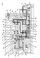
- clamping device is used to actuate a power tool chuck 3 arranged on a machine tool 2, by means of the radially adjustable clamping jaws 4, a workpiece 10 to be machined in the power chuck 3 can be clamped.
- the clamping jaws 4 of the power chuck 2 are in this case actuated via deflection lever 7 by an axially adjustable tie rod 6, which passes through the machine spindle 5 and is in driving connection with a reversible electric servomotor 11 as a drive motor via a motion converter 21.
- a motion converter 21 By means of the motion converter 21, rotoric adjustment movements of the servomotor 11 are converted into axial displacement movements of the pull rod 6.
- the servo motor 11 consists of a stator 12 and a rotor 13, the rotor shaft 14 is drivingly connected via a consisting of an output disk 15, a belt 16 and a drive pulley 17 belt drive 18 with a planetary gear 41, via one or more reduction gear 61 with the Motion converter 21 is in drive connection.
- the belt drive 18 one or more gears may be provided between the servo motor 11 and the planetary gear 41.
- the motion converter is installed in a housing 22 which is Z-shaped in cross-section.
- the motion converter 21 is used, in a subsequent to this intermediate wall 24, the reduction gear 61 is housed.
- the planetary gear 41 is arranged on an approach to the intermediate wall 24 approach 25.
- the motion converter 21 with the reduction gear 61 and the planetary gear 41 are inserted in a likewise formed as a hollow body 32 Bell 31, which is molded in the embodiment shown directly on a component 9 of the machine tool 2.
- the bell 31 is closed by a cover cover 34 which is fastened by means of screws 35 to the hollow body 32 of the bell 31.
- the servo motor 11 is held on the end cover 34 by means of screws 20.
- the composite of two stages I and II planetary gear 41 is supported on the neck 25.
- the formed as a ring gear 42 input member of the first stage I of the planetary gear 41 is in this case fixedly connected to the drive pulley 17, the sun gear 43 of the stage I, however, is fixedly mounted on the projection 25.
- the ring gear 45 of the stage II is formed by a ring gear 33 which is fixedly attached to the bell 31, the sun gear 46 is part of a double gear 52, which is also rotatably mounted on the lug 25 by means of bearing 53.
- planet carrier 48 Via a trained as a disk 49 planet carrier 48, are rotatably inserted into the bolt 50 on which the planetary gears 43 of the first stage I and the planetary gears 47 of the second stage II are arranged by means of rolling bearings 50 ', the two stages I and II are interconnected ,
- the planet carrier 48 is also rotatably mounted on roller bearings 51 on the neck 25.
- the double gear 52 which engages with the teeth 54 in the planetary gears 47 of the second stage II, thus forming the output member of the planetary gear 51 and the connecting member with the reduction gear 61.
- the second gear 55 engaged on the double gear 52 meshes with an intermediate gear 62 a which is fastened by means of screws 67 to a shaft 65 to which a toothing 63 is mounted, which in turn engages in a toothing 29 provided on the motion converter 21.
- the shaft 65 is rotatably supported in the embodiment shown by means of rolling bearings 66 in a recess 64 incorporated in the intermediate wall 24.
- the motion converter 21 is in this way via the reduction gear 61, the planetary gear 41 and the belt drive 18 with the servo motor 11, as shown in FIG. 2 characterized by the increasingly drawn line, in drive connection.
- the housing 22 of the motion converter 21 is screwed by means of screws 27 to a flange 26 which forms part of the machine spindle 5 and rotates during operation and is rotatably supported by bearings 28 in the machine tool 2.
- the machine spindle 5 is driven together with the power chuck 3.
- the movement converter 31 receiving housing 22 is thus driven at the speed with which the power chuck 3 rotates.
- the drive speed of the machine spindle 5 does not act on the servomotor 11. In these operating conditions, rather, the rotational speed of the machine spindle 5, since the congruent gears of stages I and II of the planetary gear 41 have the same number of teeth, ineffective and effectively eliminated.
- the ring gear 42 of the first stage I is thus not driven, so that act on the rotor shaft 14 of the servo motor 11 and thus on the rotor 13 no rotational movements.
- the servo motor 11 is supplied via a power line and a control unit controlled electrical energy.
- the rotor 13 and the ring gear 43 coupled to the rotor shaft 14 of the ring gear 18 of the first drive stage I of the planetary gear 41 are driven.
- the sun gear 46 is stationarily supported on the projection 25 of the housing 22, the planetary gears 43 and with these via the planet carrier 48 and the planetary gears 47 of the second stage II are driven.
- these are based in the fixed to the bell 31 ring gear 33 as ring gear 45, so that the double gear 52 rotates with and the introduced energy via the selectable austde reduction gear 61 is the motion converter 21 is supplied.
- the servo motor 11 is arranged axially parallel to the longitudinal axis thereof. Of course, it is also possible to grow this coaxially or angularly to the longitudinal axis. Also, the clamping device 1 can be formed as a full or hollow clamp.
Landscapes
- Engineering & Computer Science (AREA)
- Mechanical Engineering (AREA)
- Turning (AREA)
- Gripping On Spindles (AREA)
Priority Applications (1)
| Application Number | Priority Date | Filing Date | Title |
|---|---|---|---|
| EP10193992.4A EP2363224A3 (fr) | 2010-03-02 | 2010-12-07 | Dispositif de serrage pour machines-outils |
Applications Claiming Priority (2)
| Application Number | Priority Date | Filing Date | Title |
|---|---|---|---|
| EP20100155188 EP2363223B1 (fr) | 2010-03-02 | 2010-03-02 | Dispositif de serrage pour machines-outils |
| EP10193992.4A EP2363224A3 (fr) | 2010-03-02 | 2010-12-07 | Dispositif de serrage pour machines-outils |
Publications (2)
| Publication Number | Publication Date |
|---|---|
| EP2363224A2 true EP2363224A2 (fr) | 2011-09-07 |
| EP2363224A3 EP2363224A3 (fr) | 2016-05-25 |
Family
ID=55644764
Family Applications (1)
| Application Number | Title | Priority Date | Filing Date |
|---|---|---|---|
| EP10193992.4A Withdrawn EP2363224A3 (fr) | 2010-03-02 | 2010-12-07 | Dispositif de serrage pour machines-outils |
Country Status (1)
| Country | Link |
|---|---|
| EP (1) | EP2363224A3 (fr) |
Cited By (1)
| Publication number | Priority date | Publication date | Assignee | Title |
|---|---|---|---|---|
| EP2769788A1 (fr) | 2013-02-22 | 2014-08-27 | Karl Hiestand | Dispositif de tension pour machines-outils |
Citations (1)
| Publication number | Priority date | Publication date | Assignee | Title |
|---|---|---|---|---|
| EP0234230B1 (fr) | 1986-02-25 | 1993-05-19 | SMW Schneider & Weisshaupt GmbH | Dispositif de contrôle des mors de mandrin |
Family Cites Families (3)
| Publication number | Priority date | Publication date | Assignee | Title |
|---|---|---|---|---|
| FR1457653A (fr) * | 1965-09-13 | 1966-01-24 | Mandrin pour machine-outil | |
| DE3218084C3 (de) * | 1982-05-13 | 1990-07-12 | Bald Hubert | Vorrichtung zum erzeugen einer stelldrehbewegung |
| EP2103368A1 (fr) * | 2008-03-20 | 2009-09-23 | Karl Hiestand | Dispositif de tension pour machines-outils |
-
2010
- 2010-12-07 EP EP10193992.4A patent/EP2363224A3/fr not_active Withdrawn
Patent Citations (1)
| Publication number | Priority date | Publication date | Assignee | Title |
|---|---|---|---|---|
| EP0234230B1 (fr) | 1986-02-25 | 1993-05-19 | SMW Schneider & Weisshaupt GmbH | Dispositif de contrôle des mors de mandrin |
Cited By (1)
| Publication number | Priority date | Publication date | Assignee | Title |
|---|---|---|---|---|
| EP2769788A1 (fr) | 2013-02-22 | 2014-08-27 | Karl Hiestand | Dispositif de tension pour machines-outils |
Also Published As
| Publication number | Publication date |
|---|---|
| EP2363224A3 (fr) | 2016-05-25 |
Similar Documents
| Publication | Publication Date | Title |
|---|---|---|
| EP2384839B1 (fr) | Dispositif de tension | |
| EP2295176B1 (fr) | Agrégat de serrage | |
| EP0234230B1 (fr) | Dispositif de contrôle des mors de mandrin | |
| EP2868410B1 (fr) | Dispositif de serrage pour machines-outils | |
| EP0641621B1 (fr) | Dispositif d'entraînement rotatif | |
| DE3218084A1 (de) | Vorrichtung zum erzeugen einer stelldrehbewegung | |
| EP2103368A1 (fr) | Dispositif de tension pour machines-outils | |
| EP2796233A1 (fr) | Dispositif de couplage | |
| EP1637260B1 (fr) | Dispositif de verrouillage pour machine outil | |
| EP1313965A1 (fr) | Dispositif permettant de transformer un mouvement de rotation en mouvement axial | |
| DE1552302A1 (de) | Spannfutter fuer Werkzeugmaschinen | |
| EP2218531B1 (fr) | Dispositif de tension pour machines-outils | |
| EP2363223B1 (fr) | Dispositif de serrage pour machines-outils | |
| EP2283955A1 (fr) | Dispositif de serrage pour machines-outils | |
| EP0314945B1 (fr) | Dispositif d'actionnement de machoires d'un mandrin de serrage | |
| DE102010007399B4 (de) | Werkstück- oder Werkzeughaltevorrichtung einer Werkzeugmaschine | |
| EP2769788B1 (fr) | Dispositif de tension pour machines-outils | |
| EP2363224A2 (fr) | Dispositif de serrage pour machines-outils | |
| EP0403693B1 (fr) | Dispositif pour obtenir un couple pour un système de conversion de mouvement, spécialement pour l'ajustement des mors d'un mandrin ou de la force de serrage | |
| EP1728574B1 (fr) | Dispositif de serrage pour machine outil | |
| EP2724801A1 (fr) | Agrégat de serrage | |
| DE102019105643A1 (de) | Spanneinrichtung | |
| EP3127640B1 (fr) | Dispositif de serrage | |
| EP1163976A1 (fr) | Entrainement avec une transmission variable pour un dispositif porte outil | |
| DE102010007398B4 (de) | Arbeitsspindel für eine Werkzeugmaschine |
Legal Events
| Date | Code | Title | Description |
|---|---|---|---|
| PUAI | Public reference made under article 153(3) epc to a published international application that has entered the european phase |
Free format text: ORIGINAL CODE: 0009012 |
|
| AK | Designated contracting states |
Kind code of ref document: A2 Designated state(s): AL AT BE BG CH CY CZ DE DK EE ES FI FR GB GR HR HU IE IS IT LI LT LU LV MC MK MT NL NO PL PT RO RS SE SI SK SM TR |
|
| AX | Request for extension of the european patent |
Extension state: BA ME |
|
| PUAL | Search report despatched |
Free format text: ORIGINAL CODE: 0009013 |
|
| AK | Designated contracting states |
Kind code of ref document: A3 Designated state(s): AL AT BE BG CH CY CZ DE DK EE ES FI FR GB GR HR HU IE IS IT LI LT LU LV MC MK MT NL NO PL PT RO RS SE SI SK SM TR |
|
| AX | Request for extension of the european patent |
Extension state: BA ME |
|
| RIC1 | Information provided on ipc code assigned before grant |
Ipc: B23B 31/16 20060101AFI20160419BHEP Ipc: B23B 31/28 20060101ALI20160419BHEP Ipc: B23Q 17/00 20060101ALI20160419BHEP |
|
| STAA | Information on the status of an ep patent application or granted ep patent |
Free format text: STATUS: THE APPLICATION HAS BEEN PUBLISHED |
|
| STAA | Information on the status of an ep patent application or granted ep patent |
Free format text: STATUS: THE APPLICATION IS DEEMED TO BE WITHDRAWN |
|
| 18D | Application deemed to be withdrawn |
Effective date: 20161126 |