EP2363320B1 - Phare frontal doté d'un système de réflexion DEL doté d'une fonction de feux de brouillard et de feux de jour - Google Patents
Phare frontal doté d'un système de réflexion DEL doté d'une fonction de feux de brouillard et de feux de jour Download PDFInfo
- Publication number
- EP2363320B1 EP2363320B1 EP11000706.9A EP11000706A EP2363320B1 EP 2363320 B1 EP2363320 B1 EP 2363320B1 EP 11000706 A EP11000706 A EP 11000706A EP 2363320 B1 EP2363320 B1 EP 2363320B1
- Authority
- EP
- European Patent Office
- Prior art keywords
- light
- semiconductor light
- light source
- front headlamp
- distribution
- Prior art date
- Legal status (The legal status is an assumption and is not a legal conclusion. Google has not performed a legal analysis and makes no representation as to the accuracy of the status listed.)
- Not-in-force
Links
Images
Classifications
-
- B—PERFORMING OPERATIONS; TRANSPORTING
- B60—VEHICLES IN GENERAL
- B60Q—ARRANGEMENT OF SIGNALLING OR LIGHTING DEVICES, THE MOUNTING OR SUPPORTING THEREOF OR CIRCUITS THEREFOR, FOR VEHICLES IN GENERAL
- B60Q1/00—Arrangement of optical signalling or lighting devices, the mounting or supporting thereof or circuits therefor
- B60Q1/02—Arrangement of optical signalling or lighting devices, the mounting or supporting thereof or circuits therefor the devices being primarily intended to illuminate the way ahead or to illuminate other areas of way or environments
- B60Q1/04—Arrangement of optical signalling or lighting devices, the mounting or supporting thereof or circuits therefor the devices being primarily intended to illuminate the way ahead or to illuminate other areas of way or environments the devices being headlights
- B60Q1/18—Arrangement of optical signalling or lighting devices, the mounting or supporting thereof or circuits therefor the devices being primarily intended to illuminate the way ahead or to illuminate other areas of way or environments the devices being headlights being additional front lights
- B60Q1/20—Fog lights
-
- B—PERFORMING OPERATIONS; TRANSPORTING
- B60—VEHICLES IN GENERAL
- B60Q—ARRANGEMENT OF SIGNALLING OR LIGHTING DEVICES, THE MOUNTING OR SUPPORTING THEREOF OR CIRCUITS THEREFOR, FOR VEHICLES IN GENERAL
- B60Q1/00—Arrangement of optical signalling or lighting devices, the mounting or supporting thereof or circuits therefor
- B60Q1/26—Arrangement of optical signalling or lighting devices, the mounting or supporting thereof or circuits therefor the devices being primarily intended to indicate the vehicle, or parts thereof, or to give signals, to other traffic
- B60Q1/28—Arrangement of optical signalling or lighting devices, the mounting or supporting thereof or circuits therefor the devices being primarily intended to indicate the vehicle, or parts thereof, or to give signals, to other traffic for indicating front of vehicle
-
- F—MECHANICAL ENGINEERING; LIGHTING; HEATING; WEAPONS; BLASTING
- F21—LIGHTING
- F21S—NON-PORTABLE LIGHTING DEVICES; SYSTEMS THEREOF; VEHICLE LIGHTING DEVICES SPECIALLY ADAPTED FOR VEHICLE EXTERIORS
- F21S41/00—Illuminating devices specially adapted for vehicle exteriors, e.g. headlamps
- F21S41/10—Illuminating devices specially adapted for vehicle exteriors, e.g. headlamps characterised by the light source
- F21S41/14—Illuminating devices specially adapted for vehicle exteriors, e.g. headlamps characterised by the light source characterised by the type of light source
- F21S41/141—Light emitting diodes [LED]
- F21S41/147—Light emitting diodes [LED] the main emission direction of the LED being angled to the optical axis of the illuminating device
- F21S41/148—Light emitting diodes [LED] the main emission direction of the LED being angled to the optical axis of the illuminating device the main emission direction of the LED being perpendicular to the optical axis
-
- F—MECHANICAL ENGINEERING; LIGHTING; HEATING; WEAPONS; BLASTING
- F21—LIGHTING
- F21S—NON-PORTABLE LIGHTING DEVICES; SYSTEMS THEREOF; VEHICLE LIGHTING DEVICES SPECIALLY ADAPTED FOR VEHICLE EXTERIORS
- F21S41/00—Illuminating devices specially adapted for vehicle exteriors, e.g. headlamps
- F21S41/10—Illuminating devices specially adapted for vehicle exteriors, e.g. headlamps characterised by the light source
- F21S41/14—Illuminating devices specially adapted for vehicle exteriors, e.g. headlamps characterised by the light source characterised by the type of light source
- F21S41/141—Light emitting diodes [LED]
- F21S41/151—Light emitting diodes [LED] arranged in one or more lines
-
- F—MECHANICAL ENGINEERING; LIGHTING; HEATING; WEAPONS; BLASTING
- F21—LIGHTING
- F21S—NON-PORTABLE LIGHTING DEVICES; SYSTEMS THEREOF; VEHICLE LIGHTING DEVICES SPECIALLY ADAPTED FOR VEHICLE EXTERIORS
- F21S41/00—Illuminating devices specially adapted for vehicle exteriors, e.g. headlamps
- F21S41/60—Illuminating devices specially adapted for vehicle exteriors, e.g. headlamps characterised by a variable light distribution
- F21S41/65—Illuminating devices specially adapted for vehicle exteriors, e.g. headlamps characterised by a variable light distribution by acting on light sources
- F21S41/663—Illuminating devices specially adapted for vehicle exteriors, e.g. headlamps characterised by a variable light distribution by acting on light sources by switching light sources
-
- B—PERFORMING OPERATIONS; TRANSPORTING
- B60—VEHICLES IN GENERAL
- B60Q—ARRANGEMENT OF SIGNALLING OR LIGHTING DEVICES, THE MOUNTING OR SUPPORTING THEREOF OR CIRCUITS THEREFOR, FOR VEHICLES IN GENERAL
- B60Q2300/00—Indexing codes for automatically adjustable headlamps or automatically dimmable headlamps
- B60Q2300/05—Special features for controlling or switching of the light beam
- B60Q2300/054—Variable non-standard intensity, i.e. emission of various beam intensities different from standard intensities, e.g. continuous or stepped transitions of intensity
-
- B—PERFORMING OPERATIONS; TRANSPORTING
- B60—VEHICLES IN GENERAL
- B60Q—ARRANGEMENT OF SIGNALLING OR LIGHTING DEVICES, THE MOUNTING OR SUPPORTING THEREOF OR CIRCUITS THEREFOR, FOR VEHICLES IN GENERAL
- B60Q2400/00—Special features or arrangements of exterior signal lamps for vehicles
- B60Q2400/30—Daytime running lights [DRL], e.g. circuits or arrangements therefor
Definitions
- the present invention relates to a headlamp for a motor vehicle according to the preamble of claim 1.
- Such a headlight is from the US 2009/0129083 A known.
- two semiconductor light sources illuminate one and the same reflector. They are spatially adjacent to each other. Their main radiation directions are parallel. Due to the spatially separated arrangement different light distributions, namely a fog light distribution and a daytime running light distribution are generated with two light sources.
- a multi - purpose vehicle lighting device that has two parallel rows of light emitting diodes.
- One row serves to realize a daylight lamp, while the other serves to realize a position lamp, a fog light or a turn signal.
- the individual LEDs all have the same orientation with respect to their mounting position, so that their main radiation directions are the same orientation and thus directed in parallel.
- a motor vehicle lighting device which has a first light source and a second light source whose Hauptabstrahlraumen are mutually aligned vertically.
- the one light source illuminates a reflector and produces a fog light distribution.
- the other light source is located outside the reflector. It radiates through an opening in a panel and produces a daytime running light distribution.
- From the DE 10 2005 020 304 A1 is a motor vehicle light with at least one light source known.
- a reflector of Motor vehicle light is slidable along the main emission of the light source.
- the US 2008/018968 A1 shows a motor vehicle lamp having a filament lamp with two filaments.
- One filament serves to realize a fog lamp, while the other filament is to produce a daytime running light distribution.
- As equal-oriented filaments also the main emission directions of both filaments have the same orientation and are therefore aligned in parallel.
- WO 2007133006 A1 is known as a fog lamp for motor vehicles. Its light source has a cylindrical basic shape whose axis is directed to a transparent cover.
- the cylindrical basic shape carries a plurality of individual LEDs, of which a first group on the lateral surface, and a second group on the cover plate facing the top surface of the cylindrical basic shape is arranged. This is to provide a lamp which is compatible with an H4 bulb from its connectors and in which the approximately isotropic light emission of an incandescent lamp is simulated by the arrangement of the LEDs.
- the functions to be performed by lighting devices of a motor vehicle can be subdivided into lighting functions and signal light functions.
- Illumination light functions are used to illuminate the road and are met by floodlights.
- Examples of associated light distributions are low beam distributions, high beam distributions and fog light distributions, this list is not meant to be exhaustive.
- Signal light functions serve the purpose of making other road users aware of the motor vehicle and / or the intentions of the driver and are met by lights.
- Examples of associated light distributions are daytime running light distributions, limiting light distributions and flashing light distributions, although this list is not to be understood as conclusive.
- motor vehicles in the front area have lighting devices in the form of headlights or lights.
- each light function can be fulfilled by its own illumination device or by its own light module within a lighting device which has a plurality of light modules.
- a light module can not readily satisfy any combination of light functions, since the requirements for the spatial distribution and the illumination intensities with respect to the different light functions have great differences. For this reason, today's motor vehicles in the bow area both on the right and on the left either each have separate lighting devices in the form of low beam headlamps, high beam headlamps, fog lights, indicators, marker lights, etc. or lighting devices in which different light modules in a common housing are arranged. In particular, the light functions of the fog light and the daytime running light have hitherto been realized with separate light modules or lighting devices.
- the known solutions require both comparatively much space, which narrows the freedom of design, as well as comparatively high costs.
- the object of the invention in the specification of a headlight, which requires less space and costs less than the known solutions.
- This object is achieved with a headlight of the type mentioned, which additionally has the characterizing features of claim 1.
- a preferred embodiment is characterized in that the headlight is set up to produce a daytime running light distribution as a second light distribution.
- the inventors have recognized that these two light distributions can be fulfilled by the subject matter of the invention with a single reflector, which consists only of two differently arranged semiconductor light sources is illuminated. Often, just for these two light distributions separate lighting devices are used. In particular, the fog light function is often realized separately, as it is favored by a comparatively low arrangement below the level of the conventional headlights. It is a particular advantage that in such a constellation two lighting devices can be omitted on each side of the vehicle front.
- the headlight is adapted to generate the daytime running light distribution by a common operation of both semiconductor light sources.
- a powerful daytime running light is provided, wherein the multiple use of the fog light mounted semiconductor light source saves additional costs and facilitates the installation of the required light output in the comparatively small area of the headlamp, which is limited by geometric conditions that are necessary for the generation of the predetermined light distributions are to be kept.
- the headlight to do so is arranged to generate the daytime running light distribution with a dimmed operation of the first semiconductor light source. In this way, disturbingly large differences in intensity within the resulting from the simultaneous operation of both semiconductor light sources total light distribution can be avoided.
- headlight is set up to generate a limiting light distribution as a second light distribution.
- headlight is set up to generate a limiting light distribution as a second light distribution.
- similar advantages arise here as with a daytime running light function as a second light function. This results in particular in the advantage that a separate limiting light module or a separate limiting light can be dispensed with.
- a further preferred embodiment is characterized in that the front headlamp is adapted to generate the limiting light distribution with a dimmed operation of the second semiconductor light source or by a dimmed operation of both semiconductor light sources.
- This refinement has the additional advantage that the limiting light function can be implemented in addition to the daytime running light function without a change in the lighting technology hardware.
- the first semiconductor light source has one or more light-emitting diodes.
- LEDs are particularly advantageous because they allow an array in a row, which is favorable for the desired in the fog light wide light distribution.
- the second semiconductor light source may also have one or more light-emitting diodes.
- the two semiconductor light sources are arranged such that a main emission direction of the first semiconductor light source does not run parallel to a main emission direction of the second semiconductor light source provides a further degree of freedom for generating the light distributions.
- the main emission directions of both semiconductor light sources can be aimed at different areas of the reflector, which are each designed optimized for generating the associated light distribution. This is possible with so-called free-form reflectors.
- a transparent, a light exit surface of the headlamp covering disc optical elements which increase a horizontal divergence of the light emerging from the light exit surface in comparison to a disc having no optical elements.
- a further preferred embodiment is characterized by at least one optical element in the form of a primary optic and / or an intermediate reflector, wherein the optical element is associated with the first and / or the second semiconductor light source and is adapted to light the first semiconductor light source and / or the second To focus semiconductor light source on the reflector.
- the front headlight additionally has one or more light modules which are set up to generate further light distributions.
- This configuration reduces the space requirement required for the arrangement of all the light modules, which permits a reduction in the front headlamp or a simplified arrangement of pivotable and thus space-demanding cornering light modules.
- the headlight on no additional light modules, which are set up to produce a low-beam distribution and / or a high beam distribution.
- the invention allows the elimination of separate light modules for the generation of the second light distribution and opens up the already described retrofit option for a modern daytime running light provided by semiconductor light sources.
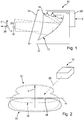
- the arrangement of the reflector 12 and the two semiconductor light sources 14 and 18 is housed within a housing 22 which is closed by a transparent disk 24.
- the transparent pane 24 thus covers in particular a light exit surface of the headlight 10.
- the two semiconductor light sources 14, 18 are controlled by a control unit 26 and supplied with electrical energy.
- the control unit 26 input signals E are supplied, which are generated via an actuation of switches by the driver of the motor vehicle or by one or more other control devices of the motor vehicle, for example, from a central lighting control unit.
- the control unit 26 is a component of the headlight 10.
- the semiconductor light sources 14, 18 are driven by a separate control unit, which is arranged spatially separated from the rest of the headlight 10.
- the front headlamp 10 is set up for intended use in a motor vehicle to emit light preferably in a direction of travel 28 and thereby, depending on the control of the two semiconductor light sources 14, 18, different light distributions in the vertical direction V and horizontal direction H to produce.
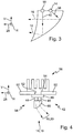
- the Fig. 2 shows a perspective view of a Headlamp 10 together with configurations of possible light distributions.
- a first light distribution 30 is shown by a solid line, while a further light distribution 32 is delimited by a dashed line.
- the first light distribution 30 is a fog light distribution with a light-dark boundary 34 and is generated when the second semiconductor light source 18 is switched off solely by the first semiconductor light source 14.
- the light-dark boundary 34 lies below a horizontal H, which represents a vertical position of the horizon. Above the cut-off line 34 results in the first light distribution 30 is a comparatively dark area.
- the fog distribution 30 is characterized among other things by a comparatively large width in the direction of the horizontal H.
- the transparent pane 24 covering the light emission surface of the headlight 10 has optical elements which increase a horizontal divergence of the light emerging from the light exit surface compared to a pane 24 which does not comprise optical elements .
- optical elements may be fine elevations and / or depressions in the form of lines, polygons, pillows, rollers, wedges and / or other light-breaking elements, which are arranged on the outside in the direction of travel 28 or the inside of the disk 24.
- the further light distribution 32 is generated when the first semiconductor light source 14 and the second semiconductor light source 18 are operated simultaneously.
- the further light distribution 32 results in one embodiment a superimposition of a weakened first light distribution 30 and a dash-dot line shown second light distribution 36, which is generated by the light 20 of the second semiconductor light source 18.
- the second light distribution 36 is distinguished by the fact that regions which lie in a comparatively dark region above the light-dark boundary 34 in the first light distribution 30 are illuminated comparatively more intensely.
- the further light distribution 32 resulting as a sum light distribution of the first light distribution 30 and the second light distribution 36 is generated in one embodiment as a daytime running light distribution by a common operation of both semiconductor light sources 14, 18. In this way, a high-performance daytime running light is provided, wherein the multiple use of the arranged for the fog light first semiconductor light source 14 provides the above advantages.
- the first semiconductor light source 14 is operated attenuated for generating the daytime running light distribution.
- the attenuation of the first light distribution 30 is in the Fig. 2 can be recognized by a course of the cumulative light distribution 32 that is retracted in the lower area in relation to the first light distribution 30.
- the lines delimiting the light distributions 30, 32 and 36 can each be considered as lines of equal intensity.
- the attenuation results in a preferred embodiment by a dimmed operation of the first semiconductor light source 14.
- the dimming that is to say the reduction of the luminous flux emanating from the first semiconductor light source 14, takes place, for example, by a reduction a duty cycle of a pulse width modulated drive signal of the first semiconductor light source 14 by the controller 26 or by driving the first semiconductor light source via another resistor with a larger resistance within the controller 26th
- the dimmed operation of the first semiconductor light source serves to reduce interfering light intensity differences between the lower region of the further light distribution 32 dominated by the luminous flux 16 of the first semiconductor light source 14 and the upper region of the further light distribution 32 dominated by the luminous flux 20 of the second semiconductor light source 18.
- the further light distribution 32 is generated without dimming the first semiconductor light source 14.
- the fog light distribution is generated solely by the semiconductor light source 14 and the daytime running light distribution alone by the semiconductor light source 18.
- the headlight 10 is adapted to generate a limiting light distribution as a second light distribution.
- a further preferred embodiment is characterized in that the headlight 10 is adapted to generate the limiting light distribution with a dimmed operation of the second semiconductor light source or by a dimmed operation of both semiconductor light sources.
- This embodiment has the additional advantage that the limiting light function in addition to the daytime running light function without a change in the lighting hardware, ie only by changing the control of the semiconductor light sources 14 and 18 can be realized.
- the desired properties are achieved essentially by the geometry of the arrangement of the two semiconductor light sources 14, 18 with respect to the reflector 12 and the shape of the reflector 12.
- the distance between the semiconductor light sources 14, 18 of the reflector 12 in the different spatial directions, the position of the optical axes and Schoabstrahlraumen the semiconductor light sources 14, 18 and the reflector 12 is determined in space under the term of the geometry of the arrangement.
- the reflector 12 is preferably realized as a so-called free-form reflector whose reflection surface is shaped so that it generates a predetermined light distribution at a predetermined illumination.
- the headlight 10 has in one embodiment, in addition to the arrangement of the reflector 12 and the two semiconductor light sources 14, 18 one or more light modules, which are adapted to produce further light distributions such as a low beam distribution, a high beam distribution and the like.
- These additional light modules can be constructed according to the reflection principle or the projection principle and can be pivotally realized in the form of gimbal-mounted assemblies about a horizontal and a vertical axis in order to enable a headlight range adjustment and / or a cornering light function.
- the front headlight 10 has no additional light modules, which are used to generate a low-beam light distribution and / or These embodiments are installed spatially separated from main headlights in bumpers of the motor vehicle.
- the invention allows the elimination of separate light modules for the generation of the second light distribution and opens up a retrofit option for a modern daytime running light provided by semiconductor light sources.
- Fig. 3 shows an inventive embodiment with a modified arrangement of the first semiconductor light source 14 with respect to the reflector 12.
- the reflector 12 is a coordinate system with a horizontal axis H, a vertical axis V and the direction of travel 28 assigned.
- the reflector has an (optical) axis, which largely points in the direction of travel 28.
- the two semiconductor light sources 14, 18 are arranged so that a main emission direction 38 of the first semiconductor light source 14 is not parallel to a main emission direction 40 of the second semiconductor light source 18. This embodiment provides a further degree of freedom for the generation of the light distributions.
- Fig. 4 shows an embodiment of a semiconductor light source 14 and / or 18.
- the semiconductor light sources 14, 18 are preferably formed as LED modules 42 which carry one or more light emitting diodes 44, 46 on a common chip 48 or on multiple chips 48, each of which a or multiple LEDs.
- the LED modules 42 are mounted on a circuit carrier 50, on which in addition to the LEDs 44, 46 and other electronic components can be arranged.
- the circuit carrier 50 is designed to be flexible or rigid depending on the mounting geometry and preferably has devices 52 for carrying out the heat of the LEDs 44, 46 to a heat sink 56 arranged on the rear side 54 of the circuit carrier 50.
- the device 52 is merely a recess through which a projection of the heat sink 56 passes through so that it bears in thermal contact with the chip 48 to receive and dissipate its electrical heat loss. Because of the fog light function and the daytime running light only comparatively small power cooling is preferably passive, ie without a forced flow, for the generation of which a blower would be required.
- a circuit carrier with integrated heat sink for example in the form of a metal core board, can be used.
- the LEDs 44, 46 are particularly preferably mounted individually or in groups switchable on the circuit substrate 50.
- the semiconductor light sources 14, 18 have at least one optical element 58 in the form of an attachment optics 60 and / or an intermediate reflector, wherein an optical element 58 is assigned to the first semiconductor light source 14 and / or the second semiconductor light source 18 and is adapted thereto To direct light 16 of the first semiconductor light source 14 and / or light 20 of the second semiconductor light source 18 onto the reflector 12.
- an optical element 58 is assigned to the first semiconductor light source 14 and / or the second semiconductor light source 18 and is adapted thereto
- For square LED's with about 1 mm edge length are preferably optical Elements with a focal length of approx. 14 mm with a distance of the LED's of approx. 3 mm used.
- the design, in the Fig. 4 has as optical element 58 a collecting optical attachment 60, which uses a total internal reflection for focusing, ie to reduce the divergence and to redirect the light emitted by LEDs 44, 46.
- a simple converging lens can serve as an example of an optical element.
- these embodiments allow a specific illumination of certain reflector areas which are optimized for the respective light distribution to be generated in the form of a change in direction and / or an increase in divergence or convergence. Reductions can be achieved dese required space, which represents another advantage.
Landscapes
- Engineering & Computer Science (AREA)
- General Engineering & Computer Science (AREA)
- Physics & Mathematics (AREA)
- Microelectronics & Electronic Packaging (AREA)
- Optics & Photonics (AREA)
- Mechanical Engineering (AREA)
- Non-Portable Lighting Devices Or Systems Thereof (AREA)
Claims (10)
- Phare frontal (10) pour un véhicule automobile, avec un agencement constitué d'un réflecteur (12) et d'une première source lumineuse semiconductrice (14), une forme du réflecteur (12) et la géométrie de l'agencement étant accordés l'un avec l'autre de façon que de la lumière (16) de la première source lumineuse semiconductrice (14) produise une première répartition de lumière (30) sous la forme d'une répartition de lumière de feux de brouillard avec une ligne de coupure (34), le phare frontal (10) comprenant une deuxième source lumineuse semiconductrice (18) qui est disposée, par rapport au réflecteur (12) de façon que sa lumière réfléchie sur le réflecteur (12) produise une deuxième répartition (36) dans laquelle des zones qui, dans la première répartition de lumière (30), sont situées dans une zone comparativement foncée au-dessus de la ligne de coupure (34), sont illuminées plus fortement, caractérisé en ce que les deux sources lumineuses semiconductrices (14, 18) sont disposées de façon qu'une direction principale d'émission (38) de la première source lumineuse semiconductrice (14) ne soit pas parallèle à une direction principale d'émission (40) de la deuxième source lumineuse semiconductrice (18).
- Phare frontal (10) selon la revendication 1, caractérisé en ce que le phare frontal (10) est agencé pour produire une répartition de feux de jour par un fonctionnement commun des deux sources lumineuses semiconductrices (14, 18) .
- Phare frontal (10) selon la revendication 2, caractérisé en ce que le phare frontal (10) est agencé pour produire une répartition de feux de jour par un fonctionnement à intensité réduite de la première source lumineuse semiconductrice (14).
- Phare frontal (10) selon l'une des revendications précédentes, caractérisé en ce que le phare frontal (10) est agencé pour produire une répartition de feux de gabarit comme répartition de feux (32) supplémentaire.
- Phare frontal (10) selon la revendication 4, caractérisé en ce que le phare frontal (10) est agencé pour produire une répartition de feux de gabarit par un fonctionnement à intensité réduite de la deuxième source lumineuse semiconductrice (18) ou par un fonctionnement à intensité réduite des deux sources lumineuses semiconductrices (14, 18) .
- Phare frontal (10) selon l'une des revendications précédentes, caractérisé en ce que la première source lumineuse semiconductrice (14) et/ou la deuxième source lumineuse semiconductrice (18) comprend une ou plusieurs diodes électroluminescentes (44, 46).
- Phare frontal (10) selon l'une des revendications précédentes, caractérisé en ce qu'une glace transparente (24) recouvrant la surface de sortie de la lumière du phare frontal (10) comprend des éléments optiques qui augmentent une divergence horizontale de la lumière (16, 20) sortant de la surface de sortie de la lumière par rapport à une glace ne comportant pas d'éléments optiques.
- Phare frontal (10) selon l'une des revendications précédentes, caractérisé par au moins un élément optique (58) sous la forme d'une optique rapportée (60) et/ou d'un réflecteur intermédiaire, un élément optique respectif (58) étant associé à la première source lumineuse semiconductrice (14) et/ou à la deuxième source lumineuse semiconductrice (18) et étant configuré pour orienter de la lumière (16) de la première source lumineuse semiconductrice et/ou de la lumière (20) de la deuxième source lumineuse semiconductrice (18) sur le réflecteur (12).
- Phare frontal (10) selon l'une des revendications précédentes, caractérisé en ce que le phare frontal (10) comprend en outre un ou plusieurs modules de lumière qui sont configurés pour produire d'autres répartitions de feux.
- Phare frontal (10) selon l'une des revendications 1 à 8, caractérisé en ce que le phare frontal (10) ne comporte pas de modules de lumière supplémentaires qui sont configurés pour produire une répartition de feux de croisement et/ou une répartition de feux de route.
Applications Claiming Priority (1)
| Application Number | Priority Date | Filing Date | Title |
|---|---|---|---|
| DE102010009640A DE102010009640A1 (de) | 2010-02-27 | 2010-02-27 | Frontscheinwerfer mit einem LED-Reflexionssystem mit Nebellicht- und Tagfahrlichtfunktion |
Publications (2)
| Publication Number | Publication Date |
|---|---|
| EP2363320A1 EP2363320A1 (fr) | 2011-09-07 |
| EP2363320B1 true EP2363320B1 (fr) | 2018-12-12 |
Family
ID=43902580
Family Applications (1)
| Application Number | Title | Priority Date | Filing Date |
|---|---|---|---|
| EP11000706.9A Not-in-force EP2363320B1 (fr) | 2010-02-27 | 2011-01-28 | Phare frontal doté d'un système de réflexion DEL doté d'une fonction de feux de brouillard et de feux de jour |
Country Status (2)
| Country | Link |
|---|---|
| EP (1) | EP2363320B1 (fr) |
| DE (1) | DE102010009640A1 (fr) |
Cited By (1)
| Publication number | Priority date | Publication date | Assignee | Title |
|---|---|---|---|---|
| DE102021121949A1 (de) | 2021-08-25 | 2023-03-02 | Bayerische Motoren Werke Aktiengesellschaft | Scheinwerfer für ein Kraftfahrzeug |
Families Citing this family (27)
| Publication number | Priority date | Publication date | Assignee | Title |
|---|---|---|---|---|
| DE102010045847A1 (de) * | 2010-09-17 | 2012-03-22 | Automotive Lighting Reutlingen Gmbh | Refelxionsmodul eines Kraftfahrzeug-Scheinwerfers |
| JP5869223B2 (ja) * | 2011-02-09 | 2016-02-24 | 株式会社小糸製作所 | 車両用前照灯 |
| DE102012101919A1 (de) * | 2012-03-07 | 2013-09-12 | Osram Opto Semiconductors Gmbh | Lichtquelle und Fahrzeug mit Lichtquelle |
| FR2989648B1 (fr) * | 2012-04-18 | 2014-05-09 | Renault Sa | Système d'éclairage pour véhicule. |
| FR2989647B1 (fr) * | 2012-04-23 | 2015-02-27 | Peugeot Citroen Automobiles Sa | Bloc optique multifonctions de vehicule, a sources lumineuses et intensite lumineuse controlables |
| CZ2012570A3 (cs) * | 2012-08-24 | 2013-10-09 | Hella Autotechnik, S.R.O. | Prídavný modul svetlometu, zejména pro motorová vozidla |
| DE102012109492A1 (de) * | 2012-10-05 | 2014-04-10 | Hella Kgaa Hueck & Co. | Beleuchtungseinheit für ein Kraftfahrzeug |
| FR3002615A1 (fr) * | 2013-02-22 | 2014-08-29 | Valeo Vision | Dispositif d'eclairage et de signalisation d'un vehicule |
| US8928226B1 (en) * | 2013-08-01 | 2015-01-06 | Myotek Pacific Corp. | Combination LED fog lamp and daytime running lamp |
| FR3010485B1 (fr) * | 2013-09-09 | 2018-01-26 | Valeo Vision | Dispositif d'eclairage et de signalisation d'un vehicule |
| FR3022325B1 (fr) * | 2014-06-16 | 2016-07-29 | Valeo Vision | Module d'eclairage et/ou de signalisation rotatif |
| FR3022324B1 (fr) * | 2014-06-16 | 2016-07-15 | Valeo Vision | Module d'eclairage et/ou de signalisation rotatif |
| EP2962559B1 (fr) | 2014-07-03 | 2022-03-09 | odelo GmbH | Phare de véhicule automobile émettant une lumière pour éviter les accidents avec du gibier |
| DE102014111445B4 (de) * | 2014-08-12 | 2022-04-14 | HELLA GmbH & Co. KGaA | Scheinwerfer für Fahrzeuge mit Primäroptikelement zur Erzeugung einer weiteren Lichtverteilung |
| DE102014226874A1 (de) * | 2014-12-22 | 2016-06-23 | Automotive Lighting Reutlingen Gmbh | Kraftfahrzeugscheinwerfer mit Hohlspiegelreflektoren |
| DE102015009096A1 (de) * | 2015-07-17 | 2017-01-19 | Marcus Wallmeyer | Scheinwerfer |
| FR3039624B1 (fr) * | 2015-07-31 | 2020-01-17 | Valeo Vision | Dispositif d'eclairage et/ou de signalisation pour vehicule |
| EP3127747A1 (fr) * | 2015-08-07 | 2017-02-08 | Valeo Vision | Dispositif d'éclairage et/ou de signalisation pour véhicule automobile |
| CN105318254A (zh) * | 2015-12-07 | 2016-02-10 | 福州雅德驰光电科技有限公司 | 远近光一体式多功能led雾灯 |
| DE102016215707B4 (de) | 2016-08-22 | 2023-08-10 | Odelo Gmbh | Kraftfahrzeugleuchte mit Wildunfallvermeidungslicht sowie Verfahren zum Betrieb eines Wildunfallvermeidungslichts |
| JP6792427B2 (ja) | 2016-11-22 | 2020-11-25 | 株式会社小糸製作所 | 車両用灯具 |
| JP7249283B2 (ja) * | 2017-10-06 | 2023-03-30 | 株式会社小糸製作所 | 車両用前照灯 |
| DE102018108567A1 (de) | 2018-04-11 | 2019-10-17 | HELLA GmbH & Co. KGaA | Scheinwerfer für Fahrzeuge |
| US10655807B2 (en) | 2018-08-29 | 2020-05-19 | Valeo North America, Inc. | Method and apparatus for vehicle lighting |
| US11951899B1 (en) | 2022-03-03 | 2024-04-09 | Stewart Laron Hill | Accessory lights for a two-wheeled vehicle |
| TWI848785B (zh) * | 2023-08-02 | 2024-07-11 | 巨鎧精密工業股份有限公司 | 整合式雙色車燈裝置 |
| FR3159003A1 (fr) * | 2024-02-07 | 2025-08-08 | Valeo Vision | Module optique d’un dispositif lumineux d’un véhicule automobile. |
Citations (2)
| Publication number | Priority date | Publication date | Assignee | Title |
|---|---|---|---|---|
| US20040223338A1 (en) * | 2003-04-25 | 2004-11-11 | Teruo Koike | Vehicle lamp |
| DE102006043298A1 (de) * | 2006-09-14 | 2008-03-27 | Hella Kgaa Hueck & Co. | Projektionsscheinwerfer für Fahrzeuge |
Family Cites Families (7)
| Publication number | Priority date | Publication date | Assignee | Title |
|---|---|---|---|---|
| DE102005020304A1 (de) * | 2005-04-30 | 2006-11-02 | Schefenacker Vision Systems Germany Gmbh | Leuchte für Fahrzeuge, vorzugsweise für Kraftfahrzeuge |
| KR100777779B1 (ko) * | 2006-05-12 | 2007-11-21 | 김인수 | 차량용 안개등 |
| JP4969958B2 (ja) * | 2006-09-13 | 2012-07-04 | 株式会社小糸製作所 | 車両用灯具 |
| JP4983278B2 (ja) * | 2007-01-31 | 2012-07-25 | スタンレー電気株式会社 | 車両用灯具 |
| KR100963966B1 (ko) * | 2007-11-21 | 2010-06-15 | 현대모비스 주식회사 | 엘이디 유닛 및 이를 구비하는 광원모듈 |
| DE102008036194B4 (de) * | 2008-08-02 | 2016-10-20 | Automotive Lighting Reutlingen Gmbh | Lichtmodul für eine Beleuchtungseinrichtung für ein Kraftfahrzeug |
| DE202009002518U1 (de) * | 2009-02-21 | 2009-04-30 | Lin, Yung-Fa, Banqiao City | Mehrzweck-Fahrzeugleuchtvorrichtung |
-
2010
- 2010-02-27 DE DE102010009640A patent/DE102010009640A1/de not_active Withdrawn
-
2011
- 2011-01-28 EP EP11000706.9A patent/EP2363320B1/fr not_active Not-in-force
Patent Citations (2)
| Publication number | Priority date | Publication date | Assignee | Title |
|---|---|---|---|---|
| US20040223338A1 (en) * | 2003-04-25 | 2004-11-11 | Teruo Koike | Vehicle lamp |
| DE102006043298A1 (de) * | 2006-09-14 | 2008-03-27 | Hella Kgaa Hueck & Co. | Projektionsscheinwerfer für Fahrzeuge |
Cited By (1)
| Publication number | Priority date | Publication date | Assignee | Title |
|---|---|---|---|---|
| DE102021121949A1 (de) | 2021-08-25 | 2023-03-02 | Bayerische Motoren Werke Aktiengesellschaft | Scheinwerfer für ein Kraftfahrzeug |
Also Published As
| Publication number | Publication date |
|---|---|
| EP2363320A1 (fr) | 2011-09-07 |
| DE102010009640A1 (de) | 2011-09-01 |
Similar Documents
| Publication | Publication Date | Title |
|---|---|---|
| EP2363320B1 (fr) | Phare frontal doté d'un système de réflexion DEL doté d'une fonction de feux de brouillard et de feux de jour | |
| EP3343091B1 (fr) | Module d'éclairage de phare de véhicule automobile | |
| EP2431657B1 (fr) | Module de réflecteur d'un phare de véhicule automobile | |
| DE102008036193B4 (de) | Beleuchtungseinrichtung für ein Kraftfahrzeug | |
| EP2339228B1 (fr) | Module d'éclairage pour un dispositif d'éclairage et dispositif d'éclairage d'un véhicule automobile doté d'un tel module d'éclairage | |
| DE102005015077B4 (de) | Fahrzeugscheinwerfer und Automobilscheinwerfer | |
| DE102010007172A1 (de) | Lichtleiter für eine Fahrzeuglampenanordnung | |
| DE102007040728B4 (de) | Fahrzeugscheinwerfer | |
| EP2338729A1 (fr) | Module de lumière pour un phare de véhicule automobile | |
| DE102009058457A1 (de) | Kraftfahrzeugbeleuchtungseinrichtung mit einem Lichtleiter und verschiedenfarbigen Lichtquellen | |
| DE102009022723A1 (de) | Von rückwärts anzubringendes Leuchtdioden-Modul für Kombinationsrücklichter an Kraftfahrzeugen | |
| DE102011081077A1 (de) | Kraftfahrzeugbeleuchtungseinrichtung | |
| DE102009022726A1 (de) | Von der Rückseite anzubringendes Leuchtdioden-Modul für Kombinationsrücklichter an Kraftfahrzeugen | |
| DE102007017756A1 (de) | Beleuchtungsvorrichtung | |
| EP2503225B1 (fr) | Dispositif d'éclairage de véhicule automobile et phare de véhicule automobile doté d'un tel dispositif d'éclairage | |
| DE202015010030U1 (de) | Leuchmodul zur Beleuchtung und/oder Signalisierung eines Kraftfahrzeugs | |
| DE102014226881A1 (de) | Kraftfahrzeugscheinwerfer mit einem Zweikammerreflexionssystem | |
| DE102004032797B4 (de) | Frontscheinwerfer eines Kraftfahrzeugs mit adaptiver Lichtverteilung | |
| DE202017001946U1 (de) | Scheinwerfer mit einem optischen System mit statischem Matrix-Abbiegelicht | |
| DE202023102261U1 (de) | Fahrzeugleuchte | |
| EP1431158B1 (fr) | Phare et feu de signalisation pour véhicule ferroviaire. | |
| WO2011012727A1 (fr) | Projecteur dans un véhicule à moteur, comportant une source de lumière semi-conducteur | |
| EP2473775B1 (fr) | Phare de véhicule à moteur doté de diodes électroluminescentes (led) | |
| DE102011084890A1 (de) | Lichtmodul einer Beleuchtungseinrichtung eines Kraftfahrzeugs | |
| DE102011090181B4 (de) | Scheinwerfer für ein Kraftfahrzeug, der eine Teilfernlicht-Lichtverteilung mit Hilfe eines Reflexionssystems erzeugt |
Legal Events
| Date | Code | Title | Description |
|---|---|---|---|
| PUAI | Public reference made under article 153(3) epc to a published international application that has entered the european phase |
Free format text: ORIGINAL CODE: 0009012 |
|
| AK | Designated contracting states |
Kind code of ref document: A1 Designated state(s): AL AT BE BG CH CY CZ DE DK EE ES FI FR GB GR HR HU IE IS IT LI LT LU LV MC MK MT NL NO PL PT RO RS SE SI SK SM TR |
|
| AX | Request for extension of the european patent |
Extension state: BA ME |
|
| 17P | Request for examination filed |
Effective date: 20120307 |
|
| RIN1 | Information on inventor provided before grant (corrected) |
Inventor name: SCHOLL, MICHAEL Inventor name: BOEBEL, DORIS Inventor name: STADE, FLORIAN |
|
| 17Q | First examination report despatched |
Effective date: 20141208 |
|
| GRAP | Despatch of communication of intention to grant a patent |
Free format text: ORIGINAL CODE: EPIDOSNIGR1 |
|
| STAA | Information on the status of an ep patent application or granted ep patent |
Free format text: STATUS: GRANT OF PATENT IS INTENDED |
|
| RIC1 | Information provided on ipc code assigned before grant |
Ipc: B60Q 1/20 20060101AFI20180516BHEP Ipc: B60Q 1/28 20060101ALI20180516BHEP Ipc: F21S 41/663 20180101ALI20180516BHEP Ipc: F21S 41/147 20180101ALI20180516BHEP |
|
| INTG | Intention to grant announced |
Effective date: 20180620 |
|
| RIN1 | Information on inventor provided before grant (corrected) |
Inventor name: BOEBEL, DORIS Inventor name: SCHOLL, MICHAEL Inventor name: STADE, FLORIAN |
|
| GRAS | Grant fee paid |
Free format text: ORIGINAL CODE: EPIDOSNIGR3 |
|
| GRAA | (expected) grant |
Free format text: ORIGINAL CODE: 0009210 |
|
| STAA | Information on the status of an ep patent application or granted ep patent |
Free format text: STATUS: THE PATENT HAS BEEN GRANTED |
|
| AK | Designated contracting states |
Kind code of ref document: B1 Designated state(s): AL AT BE BG CH CY CZ DE DK EE ES FI FR GB GR HR HU IE IS IT LI LT LU LV MC MK MT NL NO PL PT RO RS SE SI SK SM TR |
|
| REG | Reference to a national code |
Ref country code: GB Ref legal event code: FG4D Free format text: NOT ENGLISH |
|
| REG | Reference to a national code |
Ref country code: CH Ref legal event code: EP |
|
| REG | Reference to a national code |
Ref country code: AT Ref legal event code: REF Ref document number: 1075501 Country of ref document: AT Kind code of ref document: T Effective date: 20181215 |
|
| REG | Reference to a national code |
Ref country code: DE Ref legal event code: R096 Ref document number: 502011015134 Country of ref document: DE |
|
| REG | Reference to a national code |
Ref country code: IE Ref legal event code: FG4D Free format text: LANGUAGE OF EP DOCUMENT: GERMAN |
|
| REG | Reference to a national code |
Ref country code: NL Ref legal event code: MP Effective date: 20181212 |
|
| REG | Reference to a national code |
Ref country code: LT Ref legal event code: MG4D |
|
| PG25 | Lapsed in a contracting state [announced via postgrant information from national office to epo] |
Ref country code: LT Free format text: LAPSE BECAUSE OF FAILURE TO SUBMIT A TRANSLATION OF THE DESCRIPTION OR TO PAY THE FEE WITHIN THE PRESCRIBED TIME-LIMIT Effective date: 20181212 Ref country code: HR Free format text: LAPSE BECAUSE OF FAILURE TO SUBMIT A TRANSLATION OF THE DESCRIPTION OR TO PAY THE FEE WITHIN THE PRESCRIBED TIME-LIMIT Effective date: 20181212 Ref country code: BG Free format text: LAPSE BECAUSE OF FAILURE TO SUBMIT A TRANSLATION OF THE DESCRIPTION OR TO PAY THE FEE WITHIN THE PRESCRIBED TIME-LIMIT Effective date: 20190312 Ref country code: NO Free format text: LAPSE BECAUSE OF FAILURE TO SUBMIT A TRANSLATION OF THE DESCRIPTION OR TO PAY THE FEE WITHIN THE PRESCRIBED TIME-LIMIT Effective date: 20190312 Ref country code: ES Free format text: LAPSE BECAUSE OF FAILURE TO SUBMIT A TRANSLATION OF THE DESCRIPTION OR TO PAY THE FEE WITHIN THE PRESCRIBED TIME-LIMIT Effective date: 20181212 Ref country code: LV Free format text: LAPSE BECAUSE OF FAILURE TO SUBMIT A TRANSLATION OF THE DESCRIPTION OR TO PAY THE FEE WITHIN THE PRESCRIBED TIME-LIMIT Effective date: 20181212 Ref country code: FI Free format text: LAPSE BECAUSE OF FAILURE TO SUBMIT A TRANSLATION OF THE DESCRIPTION OR TO PAY THE FEE WITHIN THE PRESCRIBED TIME-LIMIT Effective date: 20181212 |
|
| PG25 | Lapsed in a contracting state [announced via postgrant information from national office to epo] |
Ref country code: AL Free format text: LAPSE BECAUSE OF FAILURE TO SUBMIT A TRANSLATION OF THE DESCRIPTION OR TO PAY THE FEE WITHIN THE PRESCRIBED TIME-LIMIT Effective date: 20181212 Ref country code: SE Free format text: LAPSE BECAUSE OF FAILURE TO SUBMIT A TRANSLATION OF THE DESCRIPTION OR TO PAY THE FEE WITHIN THE PRESCRIBED TIME-LIMIT Effective date: 20181212 Ref country code: RS Free format text: LAPSE BECAUSE OF FAILURE TO SUBMIT A TRANSLATION OF THE DESCRIPTION OR TO PAY THE FEE WITHIN THE PRESCRIBED TIME-LIMIT Effective date: 20181212 Ref country code: GR Free format text: LAPSE BECAUSE OF FAILURE TO SUBMIT A TRANSLATION OF THE DESCRIPTION OR TO PAY THE FEE WITHIN THE PRESCRIBED TIME-LIMIT Effective date: 20190313 |
|
| PGFP | Annual fee paid to national office [announced via postgrant information from national office to epo] |
Ref country code: FR Payment date: 20190204 Year of fee payment: 9 Ref country code: AT Payment date: 20190123 Year of fee payment: 9 |
|
| PG25 | Lapsed in a contracting state [announced via postgrant information from national office to epo] |
Ref country code: NL Free format text: LAPSE BECAUSE OF FAILURE TO SUBMIT A TRANSLATION OF THE DESCRIPTION OR TO PAY THE FEE WITHIN THE PRESCRIBED TIME-LIMIT Effective date: 20181212 |
|
| PG25 | Lapsed in a contracting state [announced via postgrant information from national office to epo] |
Ref country code: PL Free format text: LAPSE BECAUSE OF FAILURE TO SUBMIT A TRANSLATION OF THE DESCRIPTION OR TO PAY THE FEE WITHIN THE PRESCRIBED TIME-LIMIT Effective date: 20181212 Ref country code: IT Free format text: LAPSE BECAUSE OF FAILURE TO SUBMIT A TRANSLATION OF THE DESCRIPTION OR TO PAY THE FEE WITHIN THE PRESCRIBED TIME-LIMIT Effective date: 20181212 Ref country code: CZ Free format text: LAPSE BECAUSE OF FAILURE TO SUBMIT A TRANSLATION OF THE DESCRIPTION OR TO PAY THE FEE WITHIN THE PRESCRIBED TIME-LIMIT Effective date: 20181212 Ref country code: PT Free format text: LAPSE BECAUSE OF FAILURE TO SUBMIT A TRANSLATION OF THE DESCRIPTION OR TO PAY THE FEE WITHIN THE PRESCRIBED TIME-LIMIT Effective date: 20190412 |
|
| PG25 | Lapsed in a contracting state [announced via postgrant information from national office to epo] |
Ref country code: IS Free format text: LAPSE BECAUSE OF FAILURE TO SUBMIT A TRANSLATION OF THE DESCRIPTION OR TO PAY THE FEE WITHIN THE PRESCRIBED TIME-LIMIT Effective date: 20190412 Ref country code: RO Free format text: LAPSE BECAUSE OF FAILURE TO SUBMIT A TRANSLATION OF THE DESCRIPTION OR TO PAY THE FEE WITHIN THE PRESCRIBED TIME-LIMIT Effective date: 20181212 Ref country code: EE Free format text: LAPSE BECAUSE OF FAILURE TO SUBMIT A TRANSLATION OF THE DESCRIPTION OR TO PAY THE FEE WITHIN THE PRESCRIBED TIME-LIMIT Effective date: 20181212 Ref country code: SM Free format text: LAPSE BECAUSE OF FAILURE TO SUBMIT A TRANSLATION OF THE DESCRIPTION OR TO PAY THE FEE WITHIN THE PRESCRIBED TIME-LIMIT Effective date: 20181212 Ref country code: SK Free format text: LAPSE BECAUSE OF FAILURE TO SUBMIT A TRANSLATION OF THE DESCRIPTION OR TO PAY THE FEE WITHIN THE PRESCRIBED TIME-LIMIT Effective date: 20181212 |
|
| REG | Reference to a national code |
Ref country code: CH Ref legal event code: PL |
|
| REG | Reference to a national code |
Ref country code: DE Ref legal event code: R097 Ref document number: 502011015134 Country of ref document: DE |
|
| PG25 | Lapsed in a contracting state [announced via postgrant information from national office to epo] |
Ref country code: LU Free format text: LAPSE BECAUSE OF NON-PAYMENT OF DUE FEES Effective date: 20190128 |
|
| REG | Reference to a national code |
Ref country code: BE Ref legal event code: MM Effective date: 20190131 |
|
| PLBE | No opposition filed within time limit |
Free format text: ORIGINAL CODE: 0009261 |
|
| STAA | Information on the status of an ep patent application or granted ep patent |
Free format text: STATUS: NO OPPOSITION FILED WITHIN TIME LIMIT |
|
| REG | Reference to a national code |
Ref country code: IE Ref legal event code: MM4A |
|
| PG25 | Lapsed in a contracting state [announced via postgrant information from national office to epo] |
Ref country code: MC Free format text: LAPSE BECAUSE OF FAILURE TO SUBMIT A TRANSLATION OF THE DESCRIPTION OR TO PAY THE FEE WITHIN THE PRESCRIBED TIME-LIMIT Effective date: 20181212 Ref country code: DK Free format text: LAPSE BECAUSE OF FAILURE TO SUBMIT A TRANSLATION OF THE DESCRIPTION OR TO PAY THE FEE WITHIN THE PRESCRIBED TIME-LIMIT Effective date: 20181212 Ref country code: SI Free format text: LAPSE BECAUSE OF FAILURE TO SUBMIT A TRANSLATION OF THE DESCRIPTION OR TO PAY THE FEE WITHIN THE PRESCRIBED TIME-LIMIT Effective date: 20181212 |
|
| 26N | No opposition filed |
Effective date: 20190913 |
|
| GBPC | Gb: european patent ceased through non-payment of renewal fee |
Effective date: 20190312 |
|
| PG25 | Lapsed in a contracting state [announced via postgrant information from national office to epo] |
Ref country code: BE Free format text: LAPSE BECAUSE OF NON-PAYMENT OF DUE FEES Effective date: 20190131 |
|
| PG25 | Lapsed in a contracting state [announced via postgrant information from national office to epo] |
Ref country code: LI Free format text: LAPSE BECAUSE OF NON-PAYMENT OF DUE FEES Effective date: 20190131 Ref country code: CH Free format text: LAPSE BECAUSE OF NON-PAYMENT OF DUE FEES Effective date: 20190131 |
|
| PG25 | Lapsed in a contracting state [announced via postgrant information from national office to epo] |
Ref country code: IE Free format text: LAPSE BECAUSE OF NON-PAYMENT OF DUE FEES Effective date: 20190128 Ref country code: GB Free format text: LAPSE BECAUSE OF NON-PAYMENT OF DUE FEES Effective date: 20190312 |
|
| PG25 | Lapsed in a contracting state [announced via postgrant information from national office to epo] |
Ref country code: TR Free format text: LAPSE BECAUSE OF FAILURE TO SUBMIT A TRANSLATION OF THE DESCRIPTION OR TO PAY THE FEE WITHIN THE PRESCRIBED TIME-LIMIT Effective date: 20181212 |
|
| PG25 | Lapsed in a contracting state [announced via postgrant information from national office to epo] |
Ref country code: MT Free format text: LAPSE BECAUSE OF FAILURE TO SUBMIT A TRANSLATION OF THE DESCRIPTION OR TO PAY THE FEE WITHIN THE PRESCRIBED TIME-LIMIT Effective date: 20181212 |
|
| REG | Reference to a national code |
Ref country code: AT Ref legal event code: MM01 Ref document number: 1075501 Country of ref document: AT Kind code of ref document: T Effective date: 20200128 |
|
| PG25 | Lapsed in a contracting state [announced via postgrant information from national office to epo] |
Ref country code: FR Free format text: LAPSE BECAUSE OF NON-PAYMENT OF DUE FEES Effective date: 20200131 |
|
| REG | Reference to a national code |
Ref country code: DE Ref legal event code: R084 Ref document number: 502011015134 Country of ref document: DE |
|
| PG25 | Lapsed in a contracting state [announced via postgrant information from national office to epo] |
Ref country code: AT Free format text: LAPSE BECAUSE OF NON-PAYMENT OF DUE FEES Effective date: 20200128 |
|
| PG25 | Lapsed in a contracting state [announced via postgrant information from national office to epo] |
Ref country code: CY Free format text: LAPSE BECAUSE OF FAILURE TO SUBMIT A TRANSLATION OF THE DESCRIPTION OR TO PAY THE FEE WITHIN THE PRESCRIBED TIME-LIMIT Effective date: 20181212 |
|
| PG25 | Lapsed in a contracting state [announced via postgrant information from national office to epo] |
Ref country code: HU Free format text: LAPSE BECAUSE OF FAILURE TO SUBMIT A TRANSLATION OF THE DESCRIPTION OR TO PAY THE FEE WITHIN THE PRESCRIBED TIME-LIMIT; INVALID AB INITIO Effective date: 20110128 |
|
| PG25 | Lapsed in a contracting state [announced via postgrant information from national office to epo] |
Ref country code: MK Free format text: LAPSE BECAUSE OF FAILURE TO SUBMIT A TRANSLATION OF THE DESCRIPTION OR TO PAY THE FEE WITHIN THE PRESCRIBED TIME-LIMIT Effective date: 20181212 |
|
| PGFP | Annual fee paid to national office [announced via postgrant information from national office to epo] |
Ref country code: DE Payment date: 20221220 Year of fee payment: 13 |
|
| REG | Reference to a national code |
Ref country code: DE Ref legal event code: R119 Ref document number: 502011015134 Country of ref document: DE |
|
| PG25 | Lapsed in a contracting state [announced via postgrant information from national office to epo] |
Ref country code: DE Free format text: LAPSE BECAUSE OF NON-PAYMENT OF DUE FEES Effective date: 20240801 |
|
| PG25 | Lapsed in a contracting state [announced via postgrant information from national office to epo] |
Ref country code: DE Free format text: LAPSE BECAUSE OF NON-PAYMENT OF DUE FEES Effective date: 20240801 |