EP2363327B1 - Führungsplatte für seitlichen Airbag - Google Patents
Führungsplatte für seitlichen Airbag Download PDFInfo
- Publication number
- EP2363327B1 EP2363327B1 EP11001522A EP11001522A EP2363327B1 EP 2363327 B1 EP2363327 B1 EP 2363327B1 EP 11001522 A EP11001522 A EP 11001522A EP 11001522 A EP11001522 A EP 11001522A EP 2363327 B1 EP2363327 B1 EP 2363327B1
- Authority
- EP
- European Patent Office
- Prior art keywords
- air bag
- guide plate
- side air
- support member
- tube
- Prior art date
- Legal status (The legal status is an assumption and is not a legal conclusion. Google has not performed a legal analysis and makes no representation as to the accuracy of the status listed.)
- Ceased
Links
- 239000011247 coating layer Substances 0.000 claims description 7
- 239000004744 fabric Substances 0.000 claims description 3
- 229920003002 synthetic resin Polymers 0.000 claims description 3
- 239000000057 synthetic resin Substances 0.000 claims description 3
- 229920002994 synthetic fiber Polymers 0.000 claims description 2
- 230000003014 reinforcing effect Effects 0.000 description 7
- 238000010276 construction Methods 0.000 description 4
- 230000003247 decreasing effect Effects 0.000 description 2
- 238000004519 manufacturing process Methods 0.000 description 2
- 230000035939 shock Effects 0.000 description 2
- 238000003860 storage Methods 0.000 description 2
- 238000005452 bending Methods 0.000 description 1
- 238000005520 cutting process Methods 0.000 description 1
- 238000009434 installation Methods 0.000 description 1
- 239000000463 material Substances 0.000 description 1
- 239000002184 metal Substances 0.000 description 1
- 238000000034 method Methods 0.000 description 1
- 239000004745 nonwoven fabric Substances 0.000 description 1
- 238000004080 punching Methods 0.000 description 1
- 230000000452 restraining effect Effects 0.000 description 1
- 239000010409 thin film Substances 0.000 description 1
Images


Classifications
-
- B—PERFORMING OPERATIONS; TRANSPORTING
- B60—VEHICLES IN GENERAL
- B60R—VEHICLES, VEHICLE FITTINGS, OR VEHICLE PARTS, NOT OTHERWISE PROVIDED FOR
- B60R21/00—Arrangements or fittings on vehicles for protecting or preventing injuries to occupants or pedestrians in case of accidents or other traffic risks
- B60R21/02—Occupant safety arrangements or fittings, e.g. crash pads
- B60R21/16—Inflatable occupant restraints or confinements designed to inflate upon impact or impending impact, e.g. air bags
- B60R21/20—Arrangements for storing inflatable members in their non-use or deflated condition; Arrangement or mounting of air bag modules or components
- B60R21/213—Arrangements for storing inflatable members in their non-use or deflated condition; Arrangement or mounting of air bag modules or components in vehicle roof frames or pillars
-
- H—ELECTRICITY
- H04—ELECTRIC COMMUNICATION TECHNIQUE
- H04W—WIRELESS COMMUNICATION NETWORKS
- H04W76/00—Connection management
- H04W76/10—Connection setup
- H04W76/18—Management of setup rejection or failure
-
- B—PERFORMING OPERATIONS; TRANSPORTING
- B60—VEHICLES IN GENERAL
- B60R—VEHICLES, VEHICLE FITTINGS, OR VEHICLE PARTS, NOT OTHERWISE PROVIDED FOR
- B60R21/00—Arrangements or fittings on vehicles for protecting or preventing injuries to occupants or pedestrians in case of accidents or other traffic risks
- B60R21/02—Occupant safety arrangements or fittings, e.g. crash pads
- B60R21/16—Inflatable occupant restraints or confinements designed to inflate upon impact or impending impact, e.g. air bags
- B60R2021/161—Inflatable occupant restraints or confinements designed to inflate upon impact or impending impact, e.g. air bags characterised by additional means for controlling deployment trajectory
-
- B—PERFORMING OPERATIONS; TRANSPORTING
- B60—VEHICLES IN GENERAL
- B60R—VEHICLES, VEHICLE FITTINGS, OR VEHICLE PARTS, NOT OTHERWISE PROVIDED FOR
- B60R21/00—Arrangements or fittings on vehicles for protecting or preventing injuries to occupants or pedestrians in case of accidents or other traffic risks
- B60R21/02—Occupant safety arrangements or fittings, e.g. crash pads
- B60R21/16—Inflatable occupant restraints or confinements designed to inflate upon impact or impending impact, e.g. air bags
- B60R21/23—Inflatable members
- B60R21/231—Inflatable members characterised by their shape, construction or spatial configuration
- B60R21/232—Curtain-type airbags deploying mainly in a vertical direction from their top edge
-
- H—ELECTRICITY
- H04—ELECTRIC COMMUNICATION TECHNIQUE
- H04W—WIRELESS COMMUNICATION NETWORKS
- H04W60/00—Affiliation to network, e.g. registration; Terminating affiliation with the network, e.g. de-registration
-
- H—ELECTRICITY
- H04—ELECTRIC COMMUNICATION TECHNIQUE
- H04W—WIRELESS COMMUNICATION NETWORKS
- H04W84/00—Network topologies
- H04W84/02—Hierarchically pre-organised networks, e.g. paging networks, cellular networks, WLAN [Wireless Local Area Network] or WLL [Wireless Local Loop]
- H04W84/04—Large scale networks; Deep hierarchical networks
Definitions
- the present invention relates to a guide plate for a side airbag comprising: a fastening member fastened to an inner surface of a vehicle body and a support member bent from a lower end of the fastening member and extending toward a passenger space of a vehicle.
- a guide plate in accordance with the preamble of claim 1 is known from EP 0904 992 .
- the folded airbag tube is housed within an airbag cover formed from a non-woven fabric.
- a bracket is arranged for holding the folded airbag the bracket including a sloping guide surface as a guide plate facing the lower end of the folded airbag. Insofar the guide surface of the bracket serves as a support member bent from a lower end of a fastening leg of the bracket and is guiding the airbag tube during deployment into the direction of the passenger's space of the vehicle.
- Similar side airbags having a guide plate are further known from US 2003/00065 90 DE 10 2004 028 513 A1 , US 2006/043703 A1 , EP 1 630 046 A , US 2005/173902 A1 and EP 0 957 010 A .
- the airbag tube is housed within an airbag cover whereas a respective guide plate is only for guiding the airbag tube during deployment thereof.
- the invention has at its main object that the support member is supporting the lower surface of an air bag housing receiving a folded air bag tube and upon inflation of the air bag tube is preventing a door of the air bag housing from being rotated and that a bent member is formed on the distal end of the support member and is extending in the lengthwise direction of the support member the bent member being formed in the shape of "L" or being formed to have an inclined shape.
- the storage of the airbag tube is improved by arranging the folded airbag tube inside a housing which has a door to be opened in the case of deployment of the airbag tube.
- the support member being formed at the guide plate prevents the lower portion of the door from being rotated so that the airbag tube is prevented from being introduced into the space between a center pillar trim and an inner panel of the vehicle. Since additionally a bent member is formed on the distal end of the support member having the shape of "L" or an inclined shape in the event that the airbag tube is inflated impact force at the time the door of the airbag housing is momentarily flexed and returned toward its original position can be absorbed. As a consequence, it is possible to prevent the support member from being destroyed or deformed.
- the bent member is positioned higher than or at the same height as an upper end of a center pillar trim.
- a coating layer is formed on outer surface of the support member and the bent member whereas the coating layer can be made of synthetic resin of fabric.
- a side air bag assembly comprises a side air bag which is installed inward of a roof side rail, a center pillar trim which is installed below the roof side rail, a head liner which is installed facing the inside space of the vehicle to be bent upon deployment of the side air bag, and a guide unit for guiding the deployment of the side air bag.
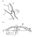
- a conventional side air bag comprises a side air bag 12 which is installed inward of a roof side rail 10, a center pillar trim 13 which is installed below the roof side rail 10, a head liner 14 which is installed facing the inside space of a vehicle to be bent upon deployment of the side air bag 12, and a guide unit 15 for guiding the deployment of the side air bag 12.
- the guide unit 15 is arranged below the side air bag 12 and is installed to be secured to inside of the center pillar trim 13.
- the guide unit 15 is composed of a guide part 16 for guiding the deployment of the side air bag 12, a fastening member 18 which is fastened to inside of the center pillar trim 13, and a connection part 17 which connects the guide part 16 and the fastening member 18 with each other.
- the side air bag is likely to be deployed inside the center pillar trim. Furthermore, when the side air bag is deployed, because it is likely to interfere with the center pillar trim, it is not easy to sequentially deploy the side air bag.
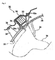
- FIGS. 2 and 3 Another side air bag for protecting a vehicle occupant from a side impact will be described below with reference to FIGS. 2 and 3 .
- a side air bag (hereinafter, simply referred to as an "air bag") 30 is installed inside of between a roof panel (not shown) and a head liner 24 to be deployed Into the passenger space of a vehicle.
- the air bag 30 installed in this way has an inflator 20 at one end thereof.
- the inflator 20 is controlled by an ECU (not shown) depending upon the level of a shock upon occurrence of a side collision to inject a large amount of gas under a high pressure into an air bag tube 36.
- a plurality of inner panels 26 and reinforcing brackets 28 are placed between the roof panel and the head liner 24.
- the head liner 24 is installed next to a door trim and a center pillar trim 22.
- the end of the head liner 24 is formed with an engagement lip 24a which is bent like a step toward the inner panel 28, and the upper end of the center pillar trim 22 is overlapped with the engagement lip 24a.
- the air bag 30 is placed adjacent to the interface between the head liner 24 and the center pillar trim 22 which are installed as described above.
- the air bag 30 has a housing 32. One end of the housing 32 is formed with a mounting part 32a which is bolted to the inner panel 26.
- the air bag tube 36 to be deployed by the inflator 20 is received in the housing 32 in a folded state.
- the housing 32 has at one side thereof a door 32b to be opened by the air bag tube 36 upon deployment of the air bag tube 36.
- the door 32b When the door 32b is opened by the air bag tube 36 upon deployment of the air bag tube 36, as the three sides of the door 32b are freed from the housing 32, the door 32b is rotated (clockwise when viewed in FIG. 3 ) and is brought into contact with the upper end of the center pillar trim 22, as a result of which the space between the center pillar trim 22 and the inner panel 26 is closed and the deployment of the air bag 30 is properly guided.
- a guide plate 34 is installed adjacent to the lower surface of the housing 32 which faces the center pillar trim 22.
- the guide plate 34 is brought into contact with the inner panel 26 to limit the rotation of the lower wall of the housing 32 and the door 32b.
- the guide plate 34 causes the door 32b to be stably held on the upper end of the center pillar trim 22.
- the air bag tube 36 when the air bag tube 36 is deployed, the upper end of the door 32b is detached from the housing 32, and the lower wall of the housing 32 is pushed downward to be rotated clockwise. Thereafter, the guide plate 34, which is positioned adjacent to the lower wall of the housing 32, is brought into contact with the inner panel 26 and limits the rotation amount of the lower wall of the housing 32 and the door 32b.
- the door 32b can be stably held on the upper end of the center pillar trim 22, and the space between the center pillar trim 22 and the inner panel 26 is dosed, so that the air bag tube 36 is prevented from being introduced into the space between the center pillar trim 22 and the inner panel 26.
- the air bag tube 38 when the air bag tube 38 is deployed; as shown in FIG. 3 by the phantom line, the space between the center pillar trim 22 and the inner panel 22 is dosed by the guide plate 34 and the door 32b of the housing 32.
- the air bag 30 being deployed is not introduced into the space between the center pillar trim 22 and the inner panel 26 and is normally deployed into the passenger space of the vehicle, whereby an occupant's side portion, particularly, head portion can be effectively protected.
- the end of the head liner 24 is detached from the upper end of the center pillar trim 22 and is bent as shown in FIG. 3 by the phantom line, thereby defining an opening through which the air bag tube 36 can be deployed.
- the guide plate 34 is simply formed of a plate while not being sufficiently considered in its strength, when the air bag tube 36 is deployed, the guide plate 34 is likely to be rotated with the lower wall of the housing 32 and destroyed to be touched with the inner panel 26 by the pressure of gas.
- Aside air bag 30 is installed facing the passenger space of a vehicle to protect an occupant from being injured.
- the side air bag 30 includes an air bag tube 36 which is folded multitude of times, an air bag housing 32 for receiving the air bag tube 36, and an inflator connected to an end of the air bag tube 36 to inject gas under a high pressure into the air bag tube 38.
- the air bag housing 32 has a door 32b on one sidewall thereof and a mounting portion 32a on the upper end thereof, which is to be fastened to an inner panel 26 by a bolt.
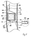
- Each guide plate 300 is installed on the air bag housing 32 at a predetermined position to support the lower surface of the air bag housing 32 (see FIG. 5 ).
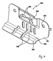
- the guide plate 300 is made of metal and is fastened to the inner panel 26 by a fastening member 390.
- the fastening member 390 has inserting holes 310 on opposite portions thereof such that the fastening member 390 can be fastened to the inner panel 26 by fastening means 301, that is, the bolts inserted through the Inserting holes 310.
- a protruded portion 320 is formed on the fastening member 390 between the inserting holes 310 to be brought into contact with one sidewall of the air bag housing 32.
- a support member 330 is bent from the lower end of the fastening member 390 to support the lower surface of the air bag housing 32.
- a bent member 340 is formed on the distal end of the support member 330 to have the sectional shape of 'L' and to extend in the lengthwise direction of the support member 330.
- bent member 340 be positioned higher than or at the same height as the upper end of the center pillar trim 22.
- a plurality of slots 360 are defined through the guide plate 300 so that the weight and material cost of the guide plate 300 can be reduced.
- fastening pieces 350 are formed by being bent on the protruded portion 320 of the guide plate 300 such that a fastening plate 304 for fastening the air bag housing 32 can be fitted on the fastening pieces 350.
- Each fastening piece 350 is formed by cutting three sides of a square pattern except one vertical side thereof using a punching machine and then by bending the cut portion through 90° about the one vertical side toward the air bag housing 32.
- the portions of the fastening pieces 350 which project out of the grooves of the fastening plate 304 are bent through 90°, whereby the fastening plate 304 can be firmly held with respect to the guide plate 300.
- the guide plate 300 is fastened to the inner panel 26.
- the air bag tube 36 is inflated, tears the door 32b of the air bag housing 32 and is deployed into the passenger space of the vehicle by opening the head liner 24.
- the guide plate 300 prevents the lower portion of the door 32b from being rotated so that the air bag tube 36 is prevented from being introduced into the space between the center pillar trim 22 and the inner panel 26.
- the air bag tube 36 can be more stably deployed into the passenger space of the vehicle.
- the bent member 340a of the guide plate 300 is bent on the distal end of the support member 330a to have an inclined sectional shape.
- the bent member 340a supports the lower portion of the door 32b of the air bag housing 32 when the door 32b is flexed. Therefore, the bent member 340a prevents the lower portion of the door 32b from being destroyed or deformed when it is momentarily flexed.
- a coating layer 370 be formed on the outer surface of the guide plate 300.
- the coating layer 370 is made of synthetic resin or fabric to deposit a thin film on the outer surfaces of the support member 330a and the bent member 240a of the guide plate 300, thereby preventing the air bag tube from being torn by a sharp edge, etc.
- the guide plate for a side air bag provides advantages as described below.
- the guide plate is formed with at least one extended member.
- the extended member guides the deploying direction of the side air bag tube so that the side air bag tube does not interfere with a center pillar when it is deployed, whereby the sequential deployment of the side air bag tube is ensured.
- the side air bag can be reliably deployed into the passenger space of a vehicle.
- the side air bag tube can be more stably deployed into the passenger space of the vehicle.
- the width of the reinforcing support member can be adjusted, whereby the guide plate for a side air bag according to the present invention can be applied irrespective of kinds of a vehicle and a side air bag.
- the air bag tube is prevented from being tom.
- the air bag tube being deployed can be more stably introduced into the passenger space of the vehicle.
- a fastening plate for fastening the side air bag can be conveniently fastened without using separate fastening means.
- the weight of the guide plate can be considerably decreased, and a manufacturing cost can be saved.
Landscapes
- Engineering & Computer Science (AREA)
- Computer Networks & Wireless Communication (AREA)
- Signal Processing (AREA)
- Mechanical Engineering (AREA)
- Air Bags (AREA)
Claims (5)
- Führungsplatte (300) für einen Seiten-Airbag (30), umfassend:ein Befestigungsglied (390), das an einer Innenfläche eines Fahrzeugaufbaus befestigt ist, und ein Stützglied (330), das das von einem unteren Ende des Befestigungsglieds (390) gebogen ist und zu einem Insassenraum des Fahrzeugs verläuft, ein gebogenes Glied (340), das am distalen Ende des Stützglieds (330) ausgebildet ist und in der Längsrichtung des Stützglieds (330) verläuft, wobei das gebogene Glied (340) in "L"-Form ausgebildet ist oder mit geneigter Form ausgebildet ist, dadurch gekennzeichnet, dass das Stützglied (330) die untere Oberfläche eines Airbag-Gehäuses (32) stützt, das einen gefalteten Airbag-Schlauch (36) aufnimmt, und nach dem Aufblasen des Airbag-Schlauchs (36) verhindert, dass eine Tür (32b) des Airbag-Gehäuses (32) gedreht wird.
- Führungsplatte nach Anspruch 1, dadurch gekennzeichnet, dass das gebogene Glied (340) höher als oder auf der gleichen Höhe wie ein oberes Ende einer Mittelsäulerizierleiste (22) angeordnet ist.
- Führungsplatte nach Anspruch 2, dadurch gekennzeichnet, dass mehrere Schlitze (360) durch die Führungsplatte (300) definiert sind.
- Führungsplatte nach Anspruch 2, dadurch gekennzeichnet, dass eine Beschichtung (370) auf einer Außenfläche des Stützglieds (330) und des gebogenen Glieds (340) ausgebildet ist.
- Führungsplatte nach Anspruch 6, dadurch gekennzeichnet, dass die Beschichtung (370) aus Kunstharz oder Stoff hergestellt ist.
Applications Claiming Priority (4)
| Application Number | Priority Date | Filing Date | Title |
|---|---|---|---|
| KR2020060008880U KR200418768Y1 (ko) | 2006-04-04 | 2006-04-04 | 사이드 에어백용 안내 플레이트 |
| KR2020060010396U KR200420468Y1 (ko) | 2006-04-18 | 2006-04-18 | 사이드 에어백용 안내 플레이트 |
| KR2020060010487U KR200420470Y1 (ko) | 2006-04-19 | 2006-04-19 | 자동차 사이드에어백용 가이드 플레이트 |
| EP07006826A EP1842741B1 (de) | 2006-04-04 | 2007-04-02 | Führungsplatte für seitlichen Airbag |
Related Parent Applications (1)
| Application Number | Title | Priority Date | Filing Date |
|---|---|---|---|
| EP07006826.7 Division | 2007-04-02 |
Publications (2)
| Publication Number | Publication Date |
|---|---|
| EP2363327A1 EP2363327A1 (de) | 2011-09-07 |
| EP2363327B1 true EP2363327B1 (de) | 2012-12-05 |
Family
ID=38226443
Family Applications (2)
| Application Number | Title | Priority Date | Filing Date |
|---|---|---|---|
| EP11001522A Ceased EP2363327B1 (de) | 2006-04-04 | 2007-04-02 | Führungsplatte für seitlichen Airbag |
| EP07006826A Ceased EP1842741B1 (de) | 2006-04-04 | 2007-04-02 | Führungsplatte für seitlichen Airbag |
Family Applications After (1)
| Application Number | Title | Priority Date | Filing Date |
|---|---|---|---|
| EP07006826A Ceased EP1842741B1 (de) | 2006-04-04 | 2007-04-02 | Führungsplatte für seitlichen Airbag |
Country Status (4)
| Country | Link |
|---|---|
| US (1) | US8141897B2 (de) |
| EP (2) | EP2363327B1 (de) |
| JP (2) | JP4987540B2 (de) |
| CN (1) | CN101712309B (de) |
Families Citing this family (16)
| Publication number | Priority date | Publication date | Assignee | Title |
|---|---|---|---|---|
| EP2363327B1 (de) * | 2006-04-04 | 2012-12-05 | Autoliv Development AB | Führungsplatte für seitlichen Airbag |
| JP5204993B2 (ja) * | 2007-06-11 | 2013-06-05 | 本田技研工業株式会社 | 車両の内装部品の配設構造 |
| JP2009262673A (ja) * | 2008-04-23 | 2009-11-12 | Takata Corp | カーテンエアバッグ用ブラケット及びカーテンエアバッグ装置 |
| JP2009292441A (ja) * | 2008-06-09 | 2009-12-17 | Takata Corp | カーテンエアバッグ用ブラケット及びカーテンエアバッグ装置 |
| KR101113672B1 (ko) * | 2009-10-30 | 2012-02-17 | 아우토리브 디벨롭먼트 아베 | 차량용 커튼에어백 램프장치 |
| JP5626121B2 (ja) | 2011-05-26 | 2014-11-19 | 豊田合成株式会社 | 頭部保護エアバッグ装置 |
| KR101292323B1 (ko) | 2011-07-12 | 2013-07-31 | 아우토리브 디벨롭먼트 아베 | 자동차 시트용 사이드 에어백 모듈 |
| JP5639131B2 (ja) * | 2012-09-07 | 2014-12-10 | 富士重工業株式会社 | カーテンエアバッグ装置の配置構造 |
| US9174602B1 (en) * | 2014-11-12 | 2015-11-03 | Toyota Motor Engineering & Manufacturing North America, Inc. | Side pillar assemblies with multi-surface retention structures for side airbags |
| DE102015006898A1 (de) * | 2015-06-03 | 2016-12-22 | Trw Airbag Systems Gmbh | Baugruppe eines Fahrzeugsicherheitssystems, Fahrzeugsicherheitssystem, Fahrzeugsicherheitseinrichtung und Verfahren zum Herstellen einer Baugruppe eines Fahrzeugsicherheitssystems |
| US9573550B1 (en) * | 2015-08-17 | 2017-02-21 | Autoliv Asp, Inc. | Side curtain airbag compression inflator bracket |
| US9643561B2 (en) * | 2015-09-16 | 2017-05-09 | Ford Global Technologies, Llc | Overhead side air curtain protective barrier |
| JP6717177B2 (ja) * | 2016-12-07 | 2020-07-01 | トヨタ自動車株式会社 | 車両用カーテンエアバッグ装置 |
| KR102647194B1 (ko) * | 2018-11-16 | 2024-03-13 | 현대자동차주식회사 | 차량용 커튼 에어백 |
| US11865990B2 (en) * | 2022-05-25 | 2024-01-09 | Autoliv Asp, Inc. | Ramp bracket for a curtain airbag |
| US11904791B1 (en) * | 2022-12-29 | 2024-02-20 | Rivian Ip Holdings, Llc | Fabric molded roof rail airbag shell |
Family Cites Families (44)
| Publication number | Priority date | Publication date | Assignee | Title |
|---|---|---|---|---|
| JP3120726B2 (ja) * | 1995-12-14 | 2000-12-25 | トヨタ自動車株式会社 | 側突用エアバッグを備えたシート構造 |
| DE69732261T2 (de) * | 1996-11-07 | 2005-12-29 | Toyoda Gosei Co., Ltd., Haruhi | Anordnung und Konstruktion einer Kraftfahrzeug-Insassenschutzvorrichtung |
| US5762363A (en) * | 1997-01-21 | 1998-06-09 | Ford Global Technologies, Inc. | Seamless side inflatable restraint deployment system |
| JP3125729B2 (ja) * | 1997-09-26 | 2001-01-22 | トヨタ自動車株式会社 | 頭部保護エアバッグ袋体の配設構造 |
| JP3093199B2 (ja) * | 1998-05-12 | 2000-10-03 | トヨタ自動車株式会社 | 頭部保護エアバッグ装置の配設構造 |
| US6371512B1 (en) * | 1998-08-03 | 2002-04-16 | Toyota Jidosha Kabushiki Kaisha | Airbag apparatus for head-protecting |
| JP3481473B2 (ja) * | 1998-10-01 | 2003-12-22 | トヨタ自動車株式会社 | 頭部保護エアバッグ袋体の配設構造 |
| US6254123B1 (en) * | 1998-08-03 | 2001-07-03 | Toyota Jidosha Kabushiki Kaisha | Mounting structure for use with a head-protecting airbag body |
| JP3702663B2 (ja) * | 1998-09-01 | 2005-10-05 | タカタ株式会社 | 乗員頭部保護バッグの設置構造 |
| JP2001122073A (ja) * | 1999-10-25 | 2001-05-08 | Toyota Motor Corp | 頭部保護エアバッグ搭載車両におけるピラーガーニッシュの取付構造 |
| JP2001163160A (ja) * | 1999-12-08 | 2001-06-19 | Daihatsu Motor Co Ltd | エアバッグ装置 |
| EP2186689B1 (de) * | 1999-12-27 | 2016-11-30 | Toyoda Gosei Co., Ltd. | Kopfschützende Airbagvorrichtung |
| JP4278261B2 (ja) * | 2000-02-10 | 2009-06-10 | 株式会社イノアックコーポレーション | カーテンエアバッグ付き車両のクォータウィンドガーニッシュ部の構造 |
| JP4534368B2 (ja) * | 2001-02-26 | 2010-09-01 | 豊田合成株式会社 | 頭部保護エアバッグ装置 |
| JP3893887B2 (ja) * | 2001-03-14 | 2007-03-14 | マツダ株式会社 | 車両の乗員保護装置 |
| DE10225677A1 (de) * | 2001-06-11 | 2003-01-16 | Honda Motor Co Ltd | Insassen-Rückhaltesystem |
| DE10137634A1 (de) * | 2001-08-03 | 2003-02-20 | Daimler Chrysler Ag | Sicherheitseinrichtung für einen Kraftwagensitz |
| DE20118457U1 (de) * | 2001-11-14 | 2002-04-04 | TRW Occupant Restraint Systems GmbH & Co. KG, 73553 Alfdorf | Seitengassackmodul für ein Fahrzeuginsassen-Schutzsystem |
| US6923286B2 (en) * | 2002-02-26 | 2005-08-02 | Toyoda Gosei Co., Ltd. | Pedestrian protecting device |
| JP3741061B2 (ja) * | 2002-02-27 | 2006-02-01 | 日産自動車株式会社 | 自動車の車体上部の衝撃吸収構造 |
| JP3935032B2 (ja) * | 2002-09-06 | 2007-06-20 | 本田技研工業株式会社 | 乗員拘束装置 |
| JP4490031B2 (ja) * | 2002-09-26 | 2010-06-23 | 日本プラスト株式会社 | エアバッグ |
| KR100471328B1 (ko) * | 2002-11-15 | 2005-03-08 | 기아자동차주식회사 | 자동차용 필라 에어백 장치 |
| DE20300254U1 (de) * | 2003-01-09 | 2003-05-15 | TRW Occupant Restraint Systems GmbH & Co. KG, 73553 Alfdorf | Befestigungsvorrichtung für ein Seitengassackmodul |
| ITTO20030066U1 (it) * | 2003-04-09 | 2004-10-10 | Fiat Auto Spa | Centina di rinforzo per il tetto di un autoveicolo con deviatore di he ad-bag integrato. |
| JP4449452B2 (ja) * | 2003-05-30 | 2010-04-14 | タカタ株式会社 | 乗員脚部保護装置 |
| KR100535049B1 (ko) * | 2003-10-24 | 2005-12-07 | 기아자동차주식회사 | 커튼형 에어백의 수납용 트림재의 장착구조 |
| JP2005219426A (ja) | 2004-02-09 | 2005-08-18 | Ricoh Co Ltd | 液体吐出ヘッド、液体カートリッジ、液体吐出装置、画像形成装置及び液体吐出ヘッドの製造方法 |
| US7175196B2 (en) * | 2004-02-09 | 2007-02-13 | Trw Vehicle Safety Systems Inc. | Support bracket for an inflatable curtain |
| US7097200B2 (en) * | 2004-04-12 | 2006-08-29 | Autoliv Asp, Inc. | Inflatable curtain trajectory bracket |
| DE102004028513A1 (de) * | 2004-06-11 | 2005-12-29 | Volkswagen Ag | Sicherheitseinrichtung für ein Fahrzeug, insbesondere für ein Kraftfahrzeug |
| KR100587106B1 (ko) | 2004-07-28 | 2006-06-08 | 대우전자부품(주) | 알루미늄 전해콘덴서 초고압용 전해액 |
| KR100599691B1 (ko) | 2004-07-28 | 2006-07-13 | 삼성에스디아이 주식회사 | 이차 전지와 이에 사용되는 전극군 |
| US7182366B2 (en) * | 2004-08-27 | 2007-02-27 | Trw Vehicle Safety Systems Inc. | Inflatable curtain deployment ramp |
| JP4343062B2 (ja) * | 2004-08-31 | 2009-10-14 | 本田技研工業株式会社 | カーテンエアバッグ装置 |
| JP4487704B2 (ja) * | 2004-09-21 | 2010-06-23 | 三菱自動車工業株式会社 | 車両のサイドドア |
| US7401805B2 (en) * | 2004-12-06 | 2008-07-22 | Key Safety Systems, Inc | Curtain air bag module |
| ES2377264T3 (es) * | 2005-04-22 | 2012-03-26 | Lisi Automotive Rapid | Elemento de fijación para la colocación y retención de un airbag en una carrocer�?a de automóvil. |
| JP4736665B2 (ja) * | 2005-09-20 | 2011-07-27 | タカタ株式会社 | カーテンエアバッグ取付金具及び取付構造、並びにカーテンエアバッグ装置 |
| JP4342501B2 (ja) * | 2005-10-18 | 2009-10-14 | トヨタ自動車株式会社 | エアバッグ装置 |
| KR100757153B1 (ko) * | 2005-12-12 | 2007-09-07 | 현대자동차주식회사 | 커튼에어백의 간섭을 방지하는 필러 램프 구조 |
| JP4907184B2 (ja) * | 2006-02-02 | 2012-03-28 | タカタ株式会社 | エアバッグ装置 |
| EP2363327B1 (de) * | 2006-04-04 | 2012-12-05 | Autoliv Development AB | Führungsplatte für seitlichen Airbag |
| US20070241542A1 (en) * | 2006-04-18 | 2007-10-18 | Mark Wallace | Air Bag Deployment Ramp |
-
2007
- 2007-04-02 EP EP11001522A patent/EP2363327B1/de not_active Ceased
- 2007-04-02 JP JP2007096728A patent/JP4987540B2/ja not_active Expired - Fee Related
- 2007-04-02 EP EP07006826A patent/EP1842741B1/de not_active Ceased
- 2007-04-03 US US11/732,488 patent/US8141897B2/en not_active Expired - Fee Related
- 2007-04-04 CN CN2009102227606A patent/CN101712309B/zh not_active Expired - Fee Related
-
2010
- 2010-02-25 JP JP2010040952A patent/JP2010149857A/ja active Pending
Also Published As
| Publication number | Publication date |
|---|---|
| EP2363327A1 (de) | 2011-09-07 |
| US20070241543A1 (en) | 2007-10-18 |
| CN101712309B (zh) | 2012-09-05 |
| JP4987540B2 (ja) | 2012-07-25 |
| US8141897B2 (en) | 2012-03-27 |
| EP1842741B1 (de) | 2013-01-23 |
| EP1842741A2 (de) | 2007-10-10 |
| CN101712309A (zh) | 2010-05-26 |
| JP2010149857A (ja) | 2010-07-08 |
| JP2007276767A (ja) | 2007-10-25 |
| EP1842741A3 (de) | 2009-06-03 |
Similar Documents
| Publication | Publication Date | Title |
|---|---|---|
| US8141897B2 (en) | Guide plate for side air bag | |
| JP4377902B2 (ja) | 車両用サイドエアーバックガイドプレート | |
| US6832800B2 (en) | Mounting structure for a pillar trim in an automobile having a curtain type airbag | |
| US8840136B2 (en) | Mounting structures for front pillar trims | |
| JP4427879B2 (ja) | ピラーガーニッシュ | |
| CN101466574A (zh) | 用于装备有头部保护安全气囊装置的车辆的柱状装饰物安装结构 | |
| US20070132217A1 (en) | Pillar ramp structure for preventing interference with curtain airbag | |
| US8172258B2 (en) | Ramp apparatus for curtain airbag for vehicle | |
| EP1332932B1 (de) | Kraftfahrzeug- Insassenschutzsystem | |
| JP3893887B2 (ja) | 車両の乗員保護装置 | |
| US20080111354A1 (en) | Apparatus for guiding deployment of curtain airbag for vehicle | |
| JP5574656B2 (ja) | カーテンエアバッグ装置 | |
| JP7751463B2 (ja) | カーテンエアバッグモジュール | |
| US20040188985A1 (en) | Vehicle with curtain air bag | |
| JP4873023B2 (ja) | 車両の乗員保護装置 | |
| EP1927518B1 (de) | Fahrzeugstrukturen oder -komponenten zur Definition einer Einsatzsteuerungsoberfläche für einen Airbag | |
| KR101003899B1 (ko) | 커튼 에어백 모듈 | |
| JP2001010440A (ja) | 頭部保護エアバッグ装置 | |
| JP4419970B2 (ja) | 車両の乗員保護装置 | |
| JP2008230472A (ja) | カーテンエアバッグ装置 | |
| US20220306036A1 (en) | Occupant protection device | |
| JP2025095688A (ja) | カーテンシールドエアバッグの支持機構 | |
| JP4345781B2 (ja) | 車両の乗員保護装置 | |
| JP5236584B2 (ja) | エアバッグ装置のカバー体及びエアバッグ装置 | |
| JP7189496B2 (ja) | 車両の上部内装構造 |
Legal Events
| Date | Code | Title | Description |
|---|---|---|---|
| PUAI | Public reference made under article 153(3) epc to a published international application that has entered the european phase |
Free format text: ORIGINAL CODE: 0009012 |
|
| AC | Divisional application: reference to earlier application |
Ref document number: 1842741 Country of ref document: EP Kind code of ref document: P |
|
| AK | Designated contracting states |
Kind code of ref document: A1 Designated state(s): DE FR GB IT |
|
| 17P | Request for examination filed |
Effective date: 20120305 |
|
| GRAP | Despatch of communication of intention to grant a patent |
Free format text: ORIGINAL CODE: EPIDOSNIGR1 |
|
| GRAS | Grant fee paid |
Free format text: ORIGINAL CODE: EPIDOSNIGR3 |
|
| GRAA | (expected) grant |
Free format text: ORIGINAL CODE: 0009210 |
|
| AC | Divisional application: reference to earlier application |
Ref document number: 1842741 Country of ref document: EP Kind code of ref document: P |
|
| AK | Designated contracting states |
Kind code of ref document: B1 Designated state(s): DE FR GB IT |
|
| REG | Reference to a national code |
Ref country code: GB Ref legal event code: FG4D |
|
| REG | Reference to a national code |
Ref country code: DE Ref legal event code: R096 Ref document number: 602007027249 Country of ref document: DE Effective date: 20130131 |
|
| PLBE | No opposition filed within time limit |
Free format text: ORIGINAL CODE: 0009261 |
|
| STAA | Information on the status of an ep patent application or granted ep patent |
Free format text: STATUS: NO OPPOSITION FILED WITHIN TIME LIMIT |
|
| 26N | No opposition filed |
Effective date: 20130906 |
|
| GBPC | Gb: european patent ceased through non-payment of renewal fee |
Effective date: 20130402 |
|
| PG25 | Lapsed in a contracting state [announced via postgrant information from national office to epo] |
Ref country code: IT Free format text: LAPSE BECAUSE OF FAILURE TO SUBMIT A TRANSLATION OF THE DESCRIPTION OR TO PAY THE FEE WITHIN THE PRESCRIBED TIME-LIMIT Effective date: 20121205 |
|
| REG | Reference to a national code |
Ref country code: DE Ref legal event code: R097 Ref document number: 602007027249 Country of ref document: DE Effective date: 20130906 |
|
| PG25 | Lapsed in a contracting state [announced via postgrant information from national office to epo] |
Ref country code: GB Free format text: LAPSE BECAUSE OF NON-PAYMENT OF DUE FEES Effective date: 20130402 |
|
| REG | Reference to a national code |
Ref country code: FR Ref legal event code: PLFP Year of fee payment: 10 |
|
| REG | Reference to a national code |
Ref country code: FR Ref legal event code: PLFP Year of fee payment: 11 |
|
| PGFP | Annual fee paid to national office [announced via postgrant information from national office to epo] |
Ref country code: FR Payment date: 20170425 Year of fee payment: 11 Ref country code: DE Payment date: 20170426 Year of fee payment: 11 |
|
| REG | Reference to a national code |
Ref country code: DE Ref legal event code: R119 Ref document number: 602007027249 Country of ref document: DE |
|
| PG25 | Lapsed in a contracting state [announced via postgrant information from national office to epo] |
Ref country code: DE Free format text: LAPSE BECAUSE OF NON-PAYMENT OF DUE FEES Effective date: 20181101 |
|
| PG25 | Lapsed in a contracting state [announced via postgrant information from national office to epo] |
Ref country code: FR Free format text: LAPSE BECAUSE OF NON-PAYMENT OF DUE FEES Effective date: 20180430 |