EP2363336B1 - Chassis eines Frontlenkers mit einem kippbaren Führerhaus - Google Patents
Chassis eines Frontlenkers mit einem kippbaren Führerhaus Download PDFInfo
- Publication number
- EP2363336B1 EP2363336B1 EP20100155149 EP10155149A EP2363336B1 EP 2363336 B1 EP2363336 B1 EP 2363336B1 EP 20100155149 EP20100155149 EP 20100155149 EP 10155149 A EP10155149 A EP 10155149A EP 2363336 B1 EP2363336 B1 EP 2363336B1
- Authority
- EP
- European Patent Office
- Prior art keywords
- frame
- members
- bearing plates
- chassis
- longitudinal members
- Prior art date
- Legal status (The legal status is an assumption and is not a legal conclusion. Google has not performed a legal analysis and makes no representation as to the accuracy of the status listed.)
- Active
Links
Images




Classifications
-
- B—PERFORMING OPERATIONS; TRANSPORTING
- B62—LAND VEHICLES FOR TRAVELLING OTHERWISE THAN ON RAILS
- B62D—MOTOR VEHICLES; TRAILERS
- B62D33/00—Superstructures for load-carrying vehicles
- B62D33/06—Drivers' cabs
- B62D33/063—Drivers' cabs movable from one position into at least one other position, e.g. tiltable, pivotable about a vertical axis, displaceable from one side of the vehicle to the other
- B62D33/067—Drivers' cabs movable from one position into at least one other position, e.g. tiltable, pivotable about a vertical axis, displaceable from one side of the vehicle to the other tiltable
-
- B—PERFORMING OPERATIONS; TRANSPORTING
- B60—VEHICLES IN GENERAL
- B60K—ARRANGEMENT OR MOUNTING OF PROPULSION UNITS OR OF TRANSMISSIONS IN VEHICLES; ARRANGEMENT OR MOUNTING OF PLURAL DIVERSE PRIME-MOVERS IN VEHICLES; AUXILIARY DRIVES FOR VEHICLES; INSTRUMENTATION OR DASHBOARDS FOR VEHICLES; ARRANGEMENTS IN CONNECTION WITH COOLING, AIR INTAKE, GAS EXHAUST OR FUEL SUPPLY OF PROPULSION UNITS IN VEHICLES
- B60K11/00—Arrangement in connection with cooling of propulsion units
- B60K11/02—Arrangement in connection with cooling of propulsion units with liquid cooling
- B60K11/04—Arrangement or mounting of radiators, radiator shutters, or radiator blinds
-
- B—PERFORMING OPERATIONS; TRANSPORTING
- B62—LAND VEHICLES FOR TRAVELLING OTHERWISE THAN ON RAILS
- B62D—MOTOR VEHICLES; TRAILERS
- B62D21/00—Understructures, i.e. chassis frame on which a vehicle body may be mounted
- B62D21/02—Understructures, i.e. chassis frame on which a vehicle body may be mounted comprising longitudinally or transversely arranged frame members
-
- B—PERFORMING OPERATIONS; TRANSPORTING
- B60—VEHICLES IN GENERAL
- B60Y—INDEXING SCHEME RELATING TO ASPECTS CROSS-CUTTING VEHICLE TECHNOLOGY
- B60Y2200/00—Type of vehicle
- B60Y2200/10—Road Vehicles
- B60Y2200/14—Trucks; Load vehicles, Busses
Definitions
- the present invention relates to a chassis of a forward control truck with a tiltable cab, according to the preamble of claim 1.
- Chassis of commercial vehicles are known in a variety of embodiments.
- An example of a known chassis is disclosed in the patent application EP 1754652 .
- a chassis comprises a frame with two longitudinal members being spaced apart from each other and being connected by a number of traverse members extending laterally between these longitudinal members.
- the frame has the function to carry the different functional units of the vehicle.
- the frame provides a number of different supports for the tiltable cab arranged above the frame, a cooler at the front end of the frame, the wheel suspensions for the front axle, the steering gear, and a front underrun protection.
- a chassis comprising the features of claim 1.
- a chassis of a forward control truck with a tiltable cab comprises a pair of bearing plates disposed at the front end of the frame.
- Each bearing plate is flanged to a front end of one of the longitudinal members of the frame so that the bearing plates are spaced apart in a lateral direction.
- the distance between the bearing plates widens toward the front end of the frame. That is, the distance between the plates at the front end of the vehicle is larger than the distance between the longitudinal members behind the bearing plates.
- the bearing plates are stabilized by a traverse member arranged at the front end of the frame. Each end of this traverse member is flanged to a front end of a respective bearing plate at one side of the vehicle.
- This traverse member has further the function to support the lower end of a cab suspension member.
- This cab suspension member can protrude in an upward direction from the plane in which the frame is located.
- the bearing plates support two opposed cooler suspension members that are disposed laterally at the cooler unit. These cooler suspension members are flanged onto flat top bearing surfaces of the bearing plates. The cooler unit itself can be received within the widened space at the front ends of the bearing plates behind the traverse member.
- a cooler of an enlarged width can be enclosed in a space between the front ends of the bearing plates, so that the distance between the longitudinal members in the remaining portion of the chassis can be relatively small.
- the bearing plates have additional functions to carry the cab suspension and a traverse member for stabilizing the frame.
- each cab suspension member is also flanged to the bearing plate to which the respective end of the traverse member is flanged.
- the cab suspension member is flanged both to the traverse member as well as to the front end of the bearing plate. This provides a rigid mounting of the respective cab suspension member, for example, at one front edge of the vehicle.
- Each of the bearing plates is provided with a support portion for receiving the front end of a leaf spring of a wheel suspension at the respective side of the chassis, said support member being located at a lower part of the bearing plate.
- each of the bearing plates also serves as a support for a wheel suspension in the lower part of the frame.
- each of the bearing plates is provided with a support portion for receiving one end of a front underrun protection member and/or a bumper extending between the bearing plates at the front end of the frame.
- the chassis comprises a second traverse member extending laterally behind said first traverse member, said second traverse member being connected to the longitudinal members of the frame by support members that are flanged to inner surfaces of said longitudinal members, each of the support members supporting one end of the second traverse member.
- This second traverse member represents a further stabilizing element of the frame and can extend below a space for receiving an engine unit of the vehicle. It may not be connected to the bearing plates but is mounted to the longitudinal members of the frame by respective support members for connection.
- the longitudinal members of the frame comprise bottom flanges extending inwardly, said support members for connecting the second traverse member to the longitudinal members there on the inner edges of these bottom flanges.
- the bottom flanges of the longitudinal members are used to support the support members for connecting the second traverse members to the longitudinal members. This provides a further stabilization of the general construction of the frame.
- the chassis comprises engine support members for supporting an engine block of the truck, said engine support members being supported by upper support surfaces on top of the support members for connecting the second traverse member to the longitudinal members.
- the engine support members are directly supported by the support members at both ends of the second traverse member.
- the enginesupport members can have any desired construction and may comprise a block of an elastomer or rubber material as a dampening unit between the engineblock and the frame.
- Fig. 1 shows a chassis 10 of a forward control truck with a tiltable cab.
- This chassis 10 comprises a frame 12 forming a structural part of the truck that carries numerous functional units of the truck vehicle. These units are not shown in the view of Fig. 1 .
- the frame 12 comprises two longitudinal members 14,16 that are spaced apart from each other.
- the longitudinal members 14,16 extend along the driving direction of the truck. In Fig. 1 , the front end of the chassis 10 is visible.
- Each longitudinal member 14,16 comprises a vertical flange 18, a top flange 20 and a bottom flange 22.
- the top flange 20 and the bottom flange 22 extend from the upper and lower edges of the vertical flange 18 inwardly, so that each longitudinal member 14,16 has a C-shaped cross-section.
- each bearing plate 24,26 is mounted to form a front end of the frame 12. More precisely, the rear end of each bearing plate 24,26 is flanged to the outer surface of the vertical flange 18 of a respective longitudinal member 14,16.
- the two bearing plates 24,26 elongate the frame 12 in the forward direction and form the foremost structural part of the frame 12.
- each bearing plate 24,26 is offset laterally in an outward direction, i. e. to the respective left/right side of the frame so that the distance between the bearing plates 24,26 widens towards the front end of the frame 12 between the rear portion of the plates 24,26 that is flanged to the longitudinal members 14,16 and the front end of the bearing plates 24,26.
- the front end of the frame 12 is stabilized by a first traverse member 28 extending horizontally in a lateral direction between the front ends of the bearing plates 24,26.
- the respective ends of this first traverse member 28 are mounted to inner surfaces of the bearing plates 24,26.
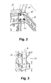
- the ends of the first traverse member 28 are provided with mounting flanges 30 extending perpendicular to the extension direction of the first traverse member 28, said mounting flanges 30 being flanged to the inner surfaces of the bearing plates 24,26 and fixed by bolts 32 extending through the mounting flanges 30 into threads provided within the bearing plates 24,26.
- a rear part of the mounting flange 30 is used to fix the end of the traverse member 28 to the respective bearing plates 24,26, the remaining front portion of the flange member 30 is free to be flanged to a lower end of a cab suspension member 34 for supporting the cab (not shown) of the truck.
- a pair of two cab suspension members 34 is shown completely in Fig. 1 . While the lower ends of these cab suspension members 34 are fixed to the front left and right corners of the frame 12, the upper ends of the cab suspension members 34 protrude upwardly from the frame. Because the cab suspension members 34 are slightly cranked, the upper ends of the cab suspension members 34 are slightly offset in the front direction of the truck with respect to the lower ends.
- cab suspension members 34 At the upper ends of the cab suspension members 34, further parts of the cab suspension are mounted, including a traverse bar 36, damping elements 38 resting on each cab suspension member 34, and further parts connected with the upper ends of the damping members 38. It is noted that the cab suspension as such is known from the state of the art and does not represent a feature of the present invention.
- each cab suspension member 34 is also flanged to a front surface 40 of the respective bearing plate 24,26.
- each lower end of the cab suspension member 34 is flanged, on one hand, to the end of the first traverse member 28 and on the other hand to the bearing plate 24,26.
- Two adjacent mounting surfaces of the lower end of the respective cab suspension member 34, standing perpendicular to each other, are flanged to respective perpendicular flange surfaces of the mounting flange 30 of the first traverse member 28 and to the front surface 40 of the bearing plate 24,26.
- Fig. 4 shows the same embodiment as in the foregoing figures, with the difference that a cooler 42 is enclosed between the front parts of the bearing plates 24,26.
- the cooler 42 as such is known from the state of the art in principle but has an enlarged width greater than the distance between the longitudinal members 14,16.
- Two vertical lateral surfaces 44,46 of the cooler 42 abut the inner surfaces of the front portions of the bearing plates 24,26.
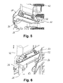
- cooler suspension members 48,50 are mounted.
- Fig. 5 and 6 show details of these cooler suspension members 48,50.
- Each of these cooler suspension members 48,50 comprises a horizontal flange 52 extending in the driving direction of the truck (parallel to the longitudinal members 14,16 of the frame 12).
- This flange 52 is flanged onto a flat top bearing surface 54 of the respective bearing plate 24,26, namely, at the front portion of the bearing plates 24,26 that is slightly offset outwardly with respect to the rear portion.
- the chassis 10 further comprises a second traverse member 60 extending laterally between the front ends of the longitudinal members 14,16 of the frame 12.
- This second traverse member 60 is slightly cranked to have a central portion 62 extending horizontally in the center between the longitudinal members 14,16, the ends of this central portion 62 being connected to the respective longitudinal members 14,16 by inclined portions 64 forming the ends of the second traverse member 60.
- the mounting of the second traverse member 60 is explained in detail with respect to Fig. 7 , also showing the overall arrangement of the second traverse member 60 between the longitudinal members 14,16.
- Other parts of the chassis, including the bearing plates 24,26, a first traverse member 28 and all parts of the cooler suspension have been omitted in Fig. 7 .
- the ends 64 of the second traverse member 60 are supported by respective support members 66 that are flanged to inner surfaces of vertical flanges 18 of the longitudinal members 14,16.
- the connection between the ends 64 of the second traverse member 60 and the support member 66 is achieved by bolt connections or the like.
- Each support member 66 is provided with a recess 68 at this bottom to receive the inner edge 70 of the bottom flange 22 of a longitudinal member 14,16.
- Fig. 8 shows a further detail of one front corner of the frame, including one longitudinal member 16, one bearing plate 26 attached to this longitudinal member 16, one part of the first traverse member 28 and the second traverse member 60 arranged behind the first traverse member 28 with respect to the driving direction and being connected to the front end of the longitudinal member 16 by the support member 66 that has already been described above with respect to Fig. 7 .
- an engine support member 62 is mounted on the support member 66.
- this engine support member 72 comprises a metal block 74 with triangular cross section. A bottom surface of this metal block 74 rests on a damping block 76 formed of an elastic material like rubber or an elastomer.
- Fig. 9 also shows a vertical flange portion 80 of the support member 66 to be flanged at the inner surface of the vertical flange 18 of the longitudinal member 16.
- the support member 66 connects the second traverse member 60 with the longitudinal members 14,16 but at the same time supports the engine support member 72 for supporting the engine of the truck.
- the mounting of the support member 66 to the longitudinal members 14,16 is independent from the mounting of the bearing plates 24,26 to the front ends of the longitudinal members 14,16.
- the bearing plates 24,26 are further provided with a support portion 82 for receiving the front end of a leaf spring (not shown in Fig. 1 ) of a wheel suspension at the respective side of the chassis 10.
- This support portion 82 at each bearing plate 24,26 extends downwardly from the rear portion of the bearing plate 24,26 and comprises two flange members 84,86 arranged in parallel spaced apart from each other in the lateral direction. Between the flanges 84,86, the end of the leaf spring can be inserted. Recesses 88 in the flanges 84,86 are for inserting a bolt or the like to mount the end of the leaf spring between the flanges 84,86.
- the bearing plates 24,26 further comprise support portions for receiving the ends of a front underrun protection at the front end of the chassis 10 and for a bumper extending between the bearing plates 24,26 at the front of the vehicle. While the front underrun protection member and the bumper are not shown in the figures, their respective ends can be mounted to the front portions of the bearing plates 24,26 with the help of insertion holes 90 provided at the flange forming the front portion of the respective bearing plates 24,26. These insertions holes 90 are provided to receive bolts or the like for fastening the front underrun protection member, the bumper or any other desired functional unit of the truck to the bearing plate 24,26 at the front end of the chassis 10. Therefore the arrangement of the holes 90 is not limited to the arrangement shown in the figures but can be modified suitably.
Landscapes
- Engineering & Computer Science (AREA)
- Chemical & Material Sciences (AREA)
- Combustion & Propulsion (AREA)
- Transportation (AREA)
- Mechanical Engineering (AREA)
- Body Structure For Vehicles (AREA)
- Vehicle Body Suspensions (AREA)
Claims (6)
- Chassis (10) eines Frontlenkerlastkraftwagens mit einem kippbaren Führerhaus, umfassend:- einen Rahmen (12) mit zwei Längselementen (14, 16), die voneinander beabstandet sind;- zumindest ein Querelement (28), das sich zwischen den Längselementen (14, 16) erstreckt;- eine Kühleraufhängung zum Tragen eines Kühlers (42) an dem vorderen Ende des Rahmens (12);- eine Führerhausaufhängung zum Tragen eines Führerhauses über dem vorderen Ende des Rahmens (12);- ein Paar Lagerplatten (24, 26), die an dem vorderen Ende des Rahmens (12) angeordnet sind, wobei jede Lagerplatte (24, 26) des Paares an ein vorderes Ende von einem der Längselemente (14, 16) derart angeflanscht ist, dass die Lagerplatten (24, 26) in einer seitlichen Richtung beabstandet ist und der Abstand zwischen den Lagerplatten (24, 26) sich in Richtung des vorderen Endes des Rahmens (12) erweitert, wobei jedes Ende des Querelements (28) an ein vorderes Ende einer jeweiligen Lagerplatte (24, 26) angeflanscht ist und das untere Ende von einem Führerhausaufhängungselement (34) trägt, wobei die Kühleraufhängung zwei entgegengesetzte Kühleraufhängungselemente (48, 50) umfasst, die seitlich an dem Kühler (42) angeordnet und an flachen oberen Lagerflächen (54) der Lagerplatten (24, 26) angeflanscht sind,dadurch gekennzeichnet, dass jede der Lagerplatten (24, 26) mit einem Trägerabschnitt (82) zur Aufnahme des vorderen Endes einer Blattfeder einer Radaufhängung an der jeweiligen Seite des Chassis versehen ist, wobei der Trägerabschnitt (82) an einem unteren Teil der Lagerplatte (24, 26) gelegen ist.
- Chassis nach Anspruch 1,
dadurch gekennzeichnet, dass jedes Führerhausaufhängungselement (48, 50) ebenfalls an die Lagerplatte (24, 26) angeflanscht ist, an die das jeweilige Ende des Querelements (28) angeflanscht ist. - Chassis nach einem der Ansprüche 1 oder 2,
dadurch gekennzeichnet, dass jede der Lagerplatten (24, 26) mit einem Trägerabschnitt zur Aufnahme eines Endes eines Frontunterfahrschutzelements und/oder eines Stoßfängers versehen ist, das bzw. der sich zwischen den Lagerplatten (24, 26) an dem vorderen Ende des Rahmens (12) erstreckt. - Chassis nach einem der vorhergehenden Ansprüche,
gekennzeichnet durch ein zweites Querelement (60), das sich seitlich hinter dem ersten Querelement (28) erstreckt, wobei das zweite Querelement (60) mit den Längselementen (14, 16) des Rahmens (12) durch Trägerelemente (66) verbunden ist, die an Innenflächen der Längselemente (14, 16) angeflanscht sind, wobei jedes der Trägerelemente (66) ein Ende (64) des zweiten Querelements (60) trägt. - Chassis nach Anspruch 4,
dadurch gekennzeichnet, dass die Längselemente (14, 16) des Rahmens (12) untere Flansche (22) umfassen, die sich nach innen erstrecken, und die Trägerelemente zum Verbinden des zweiten Querelements (60) mit den Längselementen (14, 16) auf den Innenkanten der unteren Flansche (22) aufliegen. - Chassis nach Anspruch 4 oder 5,
gekennzeichnet durch Motorträgerelemente (72) zum Tragen eines Motorblocks des Lastkraftwagens, wobei die Motorträgerelemente (72) durch obere Trägerflächen oben auf den Trägerelementen (66) zum Verbinden des Querelements (60) mit den Längselementen (14, 16) getragen sind.
Priority Applications (7)
| Application Number | Priority Date | Filing Date | Title |
|---|---|---|---|
| EP20100155149 EP2363336B1 (de) | 2010-03-02 | 2010-03-02 | Chassis eines Frontlenkers mit einem kippbaren Führerhaus |
| ES10155149T ES2395708T3 (es) | 2010-03-02 | 2010-03-02 | Chasis de un camión de control directo con una cabina basculante |
| CN201180011797.XA CN102811898B (zh) | 2010-03-02 | 2011-03-01 | 具有可倾斜的驾驶室的正向控制卡车的底盘 |
| AU2011223023A AU2011223023B2 (en) | 2010-03-02 | 2011-03-01 | Chassis of a forward control truck with a tiltable cab |
| BR112012022077A BR112012022077A2 (pt) | 2010-03-02 | 2011-03-01 | chassi de um caminhão de controle avançado com uma cabine inclinável |
| RU2012141897/11A RU2549225C2 (ru) | 2010-03-02 | 2011-03-01 | Шасси грузового автомобиля бескапотной компоновки с откидной кабиной |
| PCT/EP2011/052982 WO2011107455A1 (en) | 2010-03-02 | 2011-03-01 | Chassis of a forward control truck with a tiltable cab |
Applications Claiming Priority (1)
| Application Number | Priority Date | Filing Date | Title |
|---|---|---|---|
| EP20100155149 EP2363336B1 (de) | 2010-03-02 | 2010-03-02 | Chassis eines Frontlenkers mit einem kippbaren Führerhaus |
Publications (2)
| Publication Number | Publication Date |
|---|---|
| EP2363336A1 EP2363336A1 (de) | 2011-09-07 |
| EP2363336B1 true EP2363336B1 (de) | 2012-09-19 |
Family
ID=42341449
Family Applications (1)
| Application Number | Title | Priority Date | Filing Date |
|---|---|---|---|
| EP20100155149 Active EP2363336B1 (de) | 2010-03-02 | 2010-03-02 | Chassis eines Frontlenkers mit einem kippbaren Führerhaus |
Country Status (7)
| Country | Link |
|---|---|
| EP (1) | EP2363336B1 (de) |
| CN (1) | CN102811898B (de) |
| AU (1) | AU2011223023B2 (de) |
| BR (1) | BR112012022077A2 (de) |
| ES (1) | ES2395708T3 (de) |
| RU (1) | RU2549225C2 (de) |
| WO (1) | WO2011107455A1 (de) |
Families Citing this family (6)
| Publication number | Priority date | Publication date | Assignee | Title |
|---|---|---|---|---|
| CN103144533B (zh) * | 2013-03-19 | 2016-05-18 | 湖南南车时代电动汽车股份有限公司 | 防止对散热器冲击的客车散热器柔性悬置装置及方法 |
| CN104590375B (zh) * | 2015-02-11 | 2017-03-01 | 安徽江淮汽车集团股份有限公司 | 一种重型商用车车架前端支架 |
| JP2020111072A (ja) * | 2019-01-08 | 2020-07-27 | いすゞ自動車株式会社 | 車体フレームの補強構造 |
| CA3192651A1 (en) | 2020-09-17 | 2022-03-24 | Patrick Collignon | Frame cross member for battery electric vehicle |
| CN113460163A (zh) * | 2021-08-05 | 2021-10-01 | 太原市三高能源发展有限公司 | 汽车用前接梁转向器组合件 |
| IT202200008069A1 (it) * | 2022-04-22 | 2023-10-22 | Iveco Defence Vehicles S P A | Telaio migliorato per un veicolo pesante |
Family Cites Families (8)
| Publication number | Priority date | Publication date | Assignee | Title |
|---|---|---|---|---|
| SU787195A1 (ru) * | 1979-01-02 | 1980-12-15 | Предприятие П/Я М-5572 | Устройство дл креплени радиатора на раме транспортного средства |
| DE4006418A1 (de) * | 1990-03-01 | 1991-09-05 | Man Nutzfahrzeuge Ag | Lkw mit tragrahmen |
| SE9503271L (sv) * | 1995-09-21 | 1997-03-22 | Scania Cv Ab | Chassidel |
| DE19809209A1 (de) * | 1998-03-04 | 1999-09-09 | Man Nutzfahrzeuge Ag | Fahrgestell eines Frontlenker-Lastkraftwagen |
| DE19809268A1 (de) * | 1998-03-04 | 1999-09-09 | Man Nutzfahrzeuge Ag | Fahrgestell eines schweren Nutzfahrzeuges |
| DE10300393B3 (de) * | 2003-01-09 | 2004-07-29 | Daimlerchrysler Ag | Rahmenvorderteil für ein Nutzfahrzeug |
| DE102005038981A1 (de) * | 2005-08-18 | 2007-02-22 | Man Nutzfahrzeuge Ag | Fahrzeugrahmen für ein Nutzfahrzeug |
| DE102008030450A1 (de) * | 2008-06-26 | 2009-12-31 | Man Nutzfahrzeuge Ag | Frontquerträger eines Nutzfahrzeugs |
-
2010
- 2010-03-02 ES ES10155149T patent/ES2395708T3/es active Active
- 2010-03-02 EP EP20100155149 patent/EP2363336B1/de active Active
-
2011
- 2011-03-01 AU AU2011223023A patent/AU2011223023B2/en not_active Ceased
- 2011-03-01 WO PCT/EP2011/052982 patent/WO2011107455A1/en not_active Ceased
- 2011-03-01 RU RU2012141897/11A patent/RU2549225C2/ru not_active IP Right Cessation
- 2011-03-01 CN CN201180011797.XA patent/CN102811898B/zh not_active Expired - Fee Related
- 2011-03-01 BR BR112012022077A patent/BR112012022077A2/pt not_active Application Discontinuation
Also Published As
| Publication number | Publication date |
|---|---|
| EP2363336A1 (de) | 2011-09-07 |
| AU2011223023A1 (en) | 2012-10-18 |
| CN102811898A (zh) | 2012-12-05 |
| CN102811898B (zh) | 2015-09-16 |
| RU2012141897A (ru) | 2014-04-10 |
| ES2395708T3 (es) | 2013-02-14 |
| WO2011107455A1 (en) | 2011-09-09 |
| AU2011223023B2 (en) | 2014-05-08 |
| BR112012022077A2 (pt) | 2016-06-14 |
| RU2549225C2 (ru) | 2015-04-20 |
Similar Documents
| Publication | Publication Date | Title |
|---|---|---|
| EP1940655B1 (de) | Ein kraftfahrzeug mit einer heck-montierten batterie | |
| EP2363336B1 (de) | Chassis eines Frontlenkers mit einem kippbaren Führerhaus | |
| US7559402B2 (en) | Vehicle chassis | |
| US7857348B2 (en) | Multi-function cross members for truck frames | |
| US8801088B2 (en) | Front vehicle body reinforcing structure | |
| AU2007326492B2 (en) | Front structure for cab-over-engine vehicle | |
| US10450010B2 (en) | Cab suspension for a tiltable cab of a commercial vehicle | |
| US20060219462A1 (en) | Forward frame part for a utility vehicle | |
| CN102555749A (zh) | 电动车辆的电动机安装结构 | |
| CN101356076A (zh) | 车辆的防钻撞装置安装结构 | |
| US7389844B2 (en) | Heavy vehicle chassis having lowered rear portion | |
| CN112297807B (zh) | 电动车辆 | |
| CN103025556B (zh) | 具有纵梁和设置其上的尤其作为变速箱支承装置的弹性体支承装置的汽车 | |
| US8985605B2 (en) | Rear shock absorber mounting structure for vehicle | |
| JP2004299599A (ja) | 駆動装置の支持構造 | |
| CN106697054A (zh) | 后副车架及电动汽车 | |
| KR20190091850A (ko) | 알루미늄 재질을 갖는 프레임 타입의 전기자동차 배터리 장착 구조 | |
| CN212637654U (zh) | 前副车架总成及汽车 | |
| KR20250136568A (ko) | 트럭의 조립식 후방범퍼 | |
| CN109789745B (zh) | 平衡轴支架及平衡式悬架 | |
| JP2017030550A (ja) | フロントアンダーランプロテクタステー | |
| JP2016199182A (ja) | フロントアンダーランプロテクタの取付構造 | |
| KR20170111604A (ko) | 차량용 서브 프레임 보강유닛 | |
| KR20130093437A (ko) | 자동차용 서스펜션의 스태빌라이저바 마운팅 유닛 | |
| KR20100023532A (ko) | 사이드멤버의 마운팅 구조 |
Legal Events
| Date | Code | Title | Description |
|---|---|---|---|
| PUAI | Public reference made under article 153(3) epc to a published international application that has entered the european phase |
Free format text: ORIGINAL CODE: 0009012 |
|
| AK | Designated contracting states |
Kind code of ref document: A1 Designated state(s): AT BE BG CH CY CZ DE DK EE ES FI FR GB GR HR HU IE IS IT LI LT LU LV MC MK MT NL NO PL PT RO SE SI SK SM TR |
|
| AX | Request for extension of the european patent |
Extension state: AL BA ME RS |
|
| 17P | Request for examination filed |
Effective date: 20120131 |
|
| RIC1 | Information provided on ipc code assigned before grant |
Ipc: B62D 33/067 20060101ALI20120305BHEP Ipc: B60K 11/04 20060101ALI20120305BHEP Ipc: B62D 21/02 20060101AFI20120305BHEP |
|
| GRAP | Despatch of communication of intention to grant a patent |
Free format text: ORIGINAL CODE: EPIDOSNIGR1 |
|
| GRAS | Grant fee paid |
Free format text: ORIGINAL CODE: EPIDOSNIGR3 |
|
| GRAA | (expected) grant |
Free format text: ORIGINAL CODE: 0009210 |
|
| AK | Designated contracting states |
Kind code of ref document: B1 Designated state(s): AT BE BG CH CY CZ DE DK EE ES FI FR GB GR HR HU IE IS IT LI LT LU LV MC MK MT NL NO PL PT RO SE SI SK SM TR |
|
| REG | Reference to a national code |
Ref country code: GB Ref legal event code: FG4D |
|
| REG | Reference to a national code |
Ref country code: CH Ref legal event code: EP |
|
| REG | Reference to a national code |
Ref country code: IE Ref legal event code: FG4D |
|
| REG | Reference to a national code |
Ref country code: AT Ref legal event code: REF Ref document number: 575850 Country of ref document: AT Kind code of ref document: T Effective date: 20121015 |
|
| REG | Reference to a national code |
Ref country code: DE Ref legal event code: R096 Ref document number: 602010002826 Country of ref document: DE Effective date: 20121115 |
|
| REG | Reference to a national code |
Ref country code: SE Ref legal event code: TRGR |
|
| REG | Reference to a national code |
Ref country code: NL Ref legal event code: T3 |
|
| PG25 | Lapsed in a contracting state [announced via postgrant information from national office to epo] |
Ref country code: NO Free format text: LAPSE BECAUSE OF FAILURE TO SUBMIT A TRANSLATION OF THE DESCRIPTION OR TO PAY THE FEE WITHIN THE PRESCRIBED TIME-LIMIT Effective date: 20121219 Ref country code: HR Free format text: LAPSE BECAUSE OF FAILURE TO SUBMIT A TRANSLATION OF THE DESCRIPTION OR TO PAY THE FEE WITHIN THE PRESCRIBED TIME-LIMIT Effective date: 20120919 Ref country code: LT Free format text: LAPSE BECAUSE OF FAILURE TO SUBMIT A TRANSLATION OF THE DESCRIPTION OR TO PAY THE FEE WITHIN THE PRESCRIBED TIME-LIMIT Effective date: 20120919 Ref country code: FI Free format text: LAPSE BECAUSE OF FAILURE TO SUBMIT A TRANSLATION OF THE DESCRIPTION OR TO PAY THE FEE WITHIN THE PRESCRIBED TIME-LIMIT Effective date: 20120919 |
|
| REG | Reference to a national code |
Ref country code: ES Ref legal event code: FG2A Ref document number: 2395708 Country of ref document: ES Kind code of ref document: T3 Effective date: 20130214 |
|
| REG | Reference to a national code |
Ref country code: AT Ref legal event code: MK05 Ref document number: 575850 Country of ref document: AT Kind code of ref document: T Effective date: 20120919 |
|
| REG | Reference to a national code |
Ref country code: LT Ref legal event code: MG4D Effective date: 20120919 |
|
| PG25 | Lapsed in a contracting state [announced via postgrant information from national office to epo] |
Ref country code: SI Free format text: LAPSE BECAUSE OF FAILURE TO SUBMIT A TRANSLATION OF THE DESCRIPTION OR TO PAY THE FEE WITHIN THE PRESCRIBED TIME-LIMIT Effective date: 20120919 Ref country code: GR Free format text: LAPSE BECAUSE OF FAILURE TO SUBMIT A TRANSLATION OF THE DESCRIPTION OR TO PAY THE FEE WITHIN THE PRESCRIBED TIME-LIMIT Effective date: 20121220 Ref country code: LV Free format text: LAPSE BECAUSE OF FAILURE TO SUBMIT A TRANSLATION OF THE DESCRIPTION OR TO PAY THE FEE WITHIN THE PRESCRIBED TIME-LIMIT Effective date: 20120919 |
|
| PG25 | Lapsed in a contracting state [announced via postgrant information from national office to epo] |
Ref country code: EE Free format text: LAPSE BECAUSE OF FAILURE TO SUBMIT A TRANSLATION OF THE DESCRIPTION OR TO PAY THE FEE WITHIN THE PRESCRIBED TIME-LIMIT Effective date: 20120919 Ref country code: RO Free format text: LAPSE BECAUSE OF FAILURE TO SUBMIT A TRANSLATION OF THE DESCRIPTION OR TO PAY THE FEE WITHIN THE PRESCRIBED TIME-LIMIT Effective date: 20120919 Ref country code: BE Free format text: LAPSE BECAUSE OF FAILURE TO SUBMIT A TRANSLATION OF THE DESCRIPTION OR TO PAY THE FEE WITHIN THE PRESCRIBED TIME-LIMIT Effective date: 20120919 Ref country code: IS Free format text: LAPSE BECAUSE OF FAILURE TO SUBMIT A TRANSLATION OF THE DESCRIPTION OR TO PAY THE FEE WITHIN THE PRESCRIBED TIME-LIMIT Effective date: 20130119 Ref country code: CZ Free format text: LAPSE BECAUSE OF FAILURE TO SUBMIT A TRANSLATION OF THE DESCRIPTION OR TO PAY THE FEE WITHIN THE PRESCRIBED TIME-LIMIT Effective date: 20120919 |
|
| PG25 | Lapsed in a contracting state [announced via postgrant information from national office to epo] |
Ref country code: SK Free format text: LAPSE BECAUSE OF FAILURE TO SUBMIT A TRANSLATION OF THE DESCRIPTION OR TO PAY THE FEE WITHIN THE PRESCRIBED TIME-LIMIT Effective date: 20120919 Ref country code: PL Free format text: LAPSE BECAUSE OF FAILURE TO SUBMIT A TRANSLATION OF THE DESCRIPTION OR TO PAY THE FEE WITHIN THE PRESCRIBED TIME-LIMIT Effective date: 20120919 Ref country code: PT Free format text: LAPSE BECAUSE OF FAILURE TO SUBMIT A TRANSLATION OF THE DESCRIPTION OR TO PAY THE FEE WITHIN THE PRESCRIBED TIME-LIMIT Effective date: 20130121 |
|
| PG25 | Lapsed in a contracting state [announced via postgrant information from national office to epo] |
Ref country code: AT Free format text: LAPSE BECAUSE OF FAILURE TO SUBMIT A TRANSLATION OF THE DESCRIPTION OR TO PAY THE FEE WITHIN THE PRESCRIBED TIME-LIMIT Effective date: 20120919 |
|
| PLBE | No opposition filed within time limit |
Free format text: ORIGINAL CODE: 0009261 |
|
| STAA | Information on the status of an ep patent application or granted ep patent |
Free format text: STATUS: NO OPPOSITION FILED WITHIN TIME LIMIT |
|
| PG25 | Lapsed in a contracting state [announced via postgrant information from national office to epo] |
Ref country code: DK Free format text: LAPSE BECAUSE OF FAILURE TO SUBMIT A TRANSLATION OF THE DESCRIPTION OR TO PAY THE FEE WITHIN THE PRESCRIBED TIME-LIMIT Effective date: 20120919 Ref country code: BG Free format text: LAPSE BECAUSE OF FAILURE TO SUBMIT A TRANSLATION OF THE DESCRIPTION OR TO PAY THE FEE WITHIN THE PRESCRIBED TIME-LIMIT Effective date: 20121219 |
|
| 26N | No opposition filed |
Effective date: 20130620 |
|
| REG | Reference to a national code |
Ref country code: DE Ref legal event code: R097 Ref document number: 602010002826 Country of ref document: DE Effective date: 20130620 |
|
| PG25 | Lapsed in a contracting state [announced via postgrant information from national office to epo] |
Ref country code: MC Free format text: LAPSE BECAUSE OF NON-PAYMENT OF DUE FEES Effective date: 20130331 |
|
| PG25 | Lapsed in a contracting state [announced via postgrant information from national office to epo] |
Ref country code: CY Free format text: LAPSE BECAUSE OF FAILURE TO SUBMIT A TRANSLATION OF THE DESCRIPTION OR TO PAY THE FEE WITHIN THE PRESCRIBED TIME-LIMIT Effective date: 20120919 |
|
| REG | Reference to a national code |
Ref country code: IE Ref legal event code: MM4A |
|
| PG25 | Lapsed in a contracting state [announced via postgrant information from national office to epo] |
Ref country code: IE Free format text: LAPSE BECAUSE OF NON-PAYMENT OF DUE FEES Effective date: 20130302 |
|
| PG25 | Lapsed in a contracting state [announced via postgrant information from national office to epo] |
Ref country code: MT Free format text: LAPSE BECAUSE OF FAILURE TO SUBMIT A TRANSLATION OF THE DESCRIPTION OR TO PAY THE FEE WITHIN THE PRESCRIBED TIME-LIMIT Effective date: 20120919 |
|
| REG | Reference to a national code |
Ref country code: CH Ref legal event code: PL |
|
| PG25 | Lapsed in a contracting state [announced via postgrant information from national office to epo] |
Ref country code: CH Free format text: LAPSE BECAUSE OF NON-PAYMENT OF DUE FEES Effective date: 20140331 Ref country code: LI Free format text: LAPSE BECAUSE OF NON-PAYMENT OF DUE FEES Effective date: 20140331 |
|
| REG | Reference to a national code |
Ref country code: FR Ref legal event code: PLFP Year of fee payment: 6 |
|
| PG25 | Lapsed in a contracting state [announced via postgrant information from national office to epo] |
Ref country code: SM Free format text: LAPSE BECAUSE OF FAILURE TO SUBMIT A TRANSLATION OF THE DESCRIPTION OR TO PAY THE FEE WITHIN THE PRESCRIBED TIME-LIMIT Effective date: 20120919 |
|
| PG25 | Lapsed in a contracting state [announced via postgrant information from national office to epo] |
Ref country code: TR Free format text: LAPSE BECAUSE OF FAILURE TO SUBMIT A TRANSLATION OF THE DESCRIPTION OR TO PAY THE FEE WITHIN THE PRESCRIBED TIME-LIMIT Effective date: 20120919 |
|
| PG25 | Lapsed in a contracting state [announced via postgrant information from national office to epo] |
Ref country code: LU Free format text: LAPSE BECAUSE OF NON-PAYMENT OF DUE FEES Effective date: 20130302 Ref country code: HU Free format text: LAPSE BECAUSE OF FAILURE TO SUBMIT A TRANSLATION OF THE DESCRIPTION OR TO PAY THE FEE WITHIN THE PRESCRIBED TIME-LIMIT; INVALID AB INITIO Effective date: 20100302 Ref country code: MK Free format text: LAPSE BECAUSE OF FAILURE TO SUBMIT A TRANSLATION OF THE DESCRIPTION OR TO PAY THE FEE WITHIN THE PRESCRIBED TIME-LIMIT Effective date: 20120919 |
|
| REG | Reference to a national code |
Ref country code: FR Ref legal event code: PLFP Year of fee payment: 7 |
|
| REG | Reference to a national code |
Ref country code: FR Ref legal event code: PLFP Year of fee payment: 8 |
|
| REG | Reference to a national code |
Ref country code: FR Ref legal event code: PLFP Year of fee payment: 9 |
|
| PGFP | Annual fee paid to national office [announced via postgrant information from national office to epo] |
Ref country code: CH Payment date: 20190221 Year of fee payment: 9 Ref country code: GB Payment date: 20190327 Year of fee payment: 10 |
|
| PGFP | Annual fee paid to national office [announced via postgrant information from national office to epo] |
Ref country code: NL Payment date: 20190325 Year of fee payment: 10 Ref country code: SE Payment date: 20190328 Year of fee payment: 10 |
|
| PGFP | Annual fee paid to national office [announced via postgrant information from national office to epo] |
Ref country code: ES Payment date: 20190425 Year of fee payment: 10 |
|
| REG | Reference to a national code |
Ref country code: NL Ref legal event code: MM Effective date: 20200401 |
|
| PG25 | Lapsed in a contracting state [announced via postgrant information from national office to epo] |
Ref country code: NL Free format text: LAPSE BECAUSE OF NON-PAYMENT OF DUE FEES Effective date: 20200401 |
|
| PG25 | Lapsed in a contracting state [announced via postgrant information from national office to epo] |
Ref country code: SE Free format text: LAPSE BECAUSE OF NON-PAYMENT OF DUE FEES Effective date: 20200303 Ref country code: FR Free format text: LAPSE BECAUSE OF NON-PAYMENT OF DUE FEES Effective date: 20200331 |
|
| GBPC | Gb: european patent ceased through non-payment of renewal fee |
Effective date: 20200302 |
|
| PG25 | Lapsed in a contracting state [announced via postgrant information from national office to epo] |
Ref country code: GB Free format text: LAPSE BECAUSE OF NON-PAYMENT OF DUE FEES Effective date: 20200302 |
|
| REG | Reference to a national code |
Ref country code: ES Ref legal event code: FD2A Effective date: 20210726 |
|
| PG25 | Lapsed in a contracting state [announced via postgrant information from national office to epo] |
Ref country code: ES Free format text: LAPSE BECAUSE OF NON-PAYMENT OF DUE FEES Effective date: 20200303 |
|
| P01 | Opt-out of the competence of the unified patent court (upc) registered |
Effective date: 20230522 |
|
| PGFP | Annual fee paid to national office [announced via postgrant information from national office to epo] |
Ref country code: DE Payment date: 20260320 Year of fee payment: 17 |
|
| PGFP | Annual fee paid to national office [announced via postgrant information from national office to epo] |
Ref country code: IT Payment date: 20260311 Year of fee payment: 17 |