EP2363627B1 - Liaison câblée pour tansfer de fluides - Google Patents
Liaison câblée pour tansfer de fluides Download PDFInfo
- Publication number
- EP2363627B1 EP2363627B1 EP11168387.6A EP11168387A EP2363627B1 EP 2363627 B1 EP2363627 B1 EP 2363627B1 EP 11168387 A EP11168387 A EP 11168387A EP 2363627 B1 EP2363627 B1 EP 2363627B1
- Authority
- EP
- European Patent Office
- Prior art keywords
- pipeline
- connector
- heating
- line
- connection
- Prior art date
- Legal status (The legal status is an assumption and is not a legal conclusion. Google has not performed a legal analysis and makes no representation as to the accuracy of the status listed.)
- Active
Links
Images




Classifications
-
- F—MECHANICAL ENGINEERING; LIGHTING; HEATING; WEAPONS; BLASTING
- F16—ENGINEERING ELEMENTS AND UNITS; GENERAL MEASURES FOR PRODUCING AND MAINTAINING EFFECTIVE FUNCTIONING OF MACHINES OR INSTALLATIONS; THERMAL INSULATION IN GENERAL
- F16L—PIPES; JOINTS OR FITTINGS FOR PIPES; SUPPORTS FOR PIPES, CABLES OR PROTECTIVE TUBING; MEANS FOR THERMAL INSULATION IN GENERAL
- F16L25/00—Construction or details of pipe joints not provided for in, or of interest apart from, groups F16L13/00 - F16L23/00
- F16L25/01—Construction or details of pipe joints not provided for in, or of interest apart from, groups F16L13/00 - F16L23/00 specially adapted for realising electrical conduction between the two pipe ends of the joint or between parts thereof
-
- F—MECHANICAL ENGINEERING; LIGHTING; HEATING; WEAPONS; BLASTING
- F16—ENGINEERING ELEMENTS AND UNITS; GENERAL MEASURES FOR PRODUCING AND MAINTAINING EFFECTIVE FUNCTIONING OF MACHINES OR INSTALLATIONS; THERMAL INSULATION IN GENERAL
- F16L—PIPES; JOINTS OR FITTINGS FOR PIPES; SUPPORTS FOR PIPES, CABLES OR PROTECTIVE TUBING; MEANS FOR THERMAL INSULATION IN GENERAL
- F16L53/00—Heating of pipes or pipe systems; Cooling of pipes or pipe systems
- F16L53/30—Heating of pipes or pipe systems
- F16L53/35—Ohmic-resistance heating
- F16L53/38—Ohmic-resistance heating using elongate electric heating elements, e.g. wires or ribbons
-
- H—ELECTRICITY
- H05—ELECTRIC TECHNIQUES NOT OTHERWISE PROVIDED FOR
- H05B—ELECTRIC HEATING; ELECTRIC LIGHT SOURCES NOT OTHERWISE PROVIDED FOR; CIRCUIT ARRANGEMENTS FOR ELECTRIC LIGHT SOURCES, IN GENERAL
- H05B3/00—Ohmic-resistance heating
- H05B3/40—Heating elements having the shape of rods or tubes
- H05B3/42—Heating elements having the shape of rods or tubes non-flexible
-
- H—ELECTRICITY
- H05—ELECTRIC TECHNIQUES NOT OTHERWISE PROVIDED FOR
- H05B—ELECTRIC HEATING; ELECTRIC LIGHT SOURCES NOT OTHERWISE PROVIDED FOR; CIRCUIT ARRANGEMENTS FOR ELECTRIC LIGHT SOURCES, IN GENERAL
- H05B3/00—Ohmic-resistance heating
- H05B3/40—Heating elements having the shape of rods or tubes
- H05B3/54—Heating elements having the shape of rods or tubes flexible
-
- F—MECHANICAL ENGINEERING; LIGHTING; HEATING; WEAPONS; BLASTING
- F01—MACHINES OR ENGINES IN GENERAL; ENGINE PLANTS IN GENERAL; STEAM ENGINES
- F01N—GAS-FLOW SILENCERS OR EXHAUST APPARATUS FOR MACHINES OR ENGINES IN GENERAL; GAS-FLOW SILENCERS OR EXHAUST APPARATUS FOR INTERNAL-COMBUSTION ENGINES
- F01N2610/00—Adding substances to exhaust gases
- F01N2610/02—Adding substances to exhaust gases the substance being ammonia or urea
-
- F—MECHANICAL ENGINEERING; LIGHTING; HEATING; WEAPONS; BLASTING
- F01—MACHINES OR ENGINES IN GENERAL; ENGINE PLANTS IN GENERAL; STEAM ENGINES
- F01N—GAS-FLOW SILENCERS OR EXHAUST APPARATUS FOR MACHINES OR ENGINES IN GENERAL; GAS-FLOW SILENCERS OR EXHAUST APPARATUS FOR INTERNAL-COMBUSTION ENGINES
- F01N2610/00—Adding substances to exhaust gases
- F01N2610/10—Adding substances to exhaust gases the substance being heated, e.g. by heating tank or supply line of the added substance
-
- F—MECHANICAL ENGINEERING; LIGHTING; HEATING; WEAPONS; BLASTING
- F01—MACHINES OR ENGINES IN GENERAL; ENGINE PLANTS IN GENERAL; STEAM ENGINES
- F01N—GAS-FLOW SILENCERS OR EXHAUST APPARATUS FOR MACHINES OR ENGINES IN GENERAL; GAS-FLOW SILENCERS OR EXHAUST APPARATUS FOR INTERNAL-COMBUSTION ENGINES
- F01N2610/00—Adding substances to exhaust gases
- F01N2610/14—Arrangements for the supply of substances, e.g. conduits
-
- H—ELECTRICITY
- H01—ELECTRIC ELEMENTS
- H01R—ELECTRICALLY-CONDUCTIVE CONNECTIONS; STRUCTURAL ASSOCIATIONS OF A PLURALITY OF MUTUALLY-INSULATED ELECTRICAL CONNECTING ELEMENTS; COUPLING DEVICES; CURRENT COLLECTORS
- H01R13/00—Details of coupling devices of the kinds covered by groups H01R12/70 or H01R24/00 - H01R33/00
- H01R13/005—Electrical coupling combined with fluidic coupling
-
- Y—GENERAL TAGGING OF NEW TECHNOLOGICAL DEVELOPMENTS; GENERAL TAGGING OF CROSS-SECTIONAL TECHNOLOGIES SPANNING OVER SEVERAL SECTIONS OF THE IPC; TECHNICAL SUBJECTS COVERED BY FORMER USPC CROSS-REFERENCE ART COLLECTIONS [XRACs] AND DIGESTS
- Y10—TECHNICAL SUBJECTS COVERED BY FORMER USPC
- Y10T—TECHNICAL SUBJECTS COVERED BY FORMER US CLASSIFICATION
- Y10T137/00—Fluid handling
- Y10T137/5327—Hydrant type
- Y10T137/5456—With casing
- Y10T137/5474—With heater
-
- Y—GENERAL TAGGING OF NEW TECHNOLOGICAL DEVELOPMENTS; GENERAL TAGGING OF CROSS-SECTIONAL TECHNOLOGIES SPANNING OVER SEVERAL SECTIONS OF THE IPC; TECHNICAL SUBJECTS COVERED BY FORMER USPC CROSS-REFERENCE ART COLLECTIONS [XRACs] AND DIGESTS
- Y10—TECHNICAL SUBJECTS COVERED BY FORMER USPC
- Y10T—TECHNICAL SUBJECTS COVERED BY FORMER US CLASSIFICATION
- Y10T137/00—Fluid handling
- Y10T137/5762—With leakage or drip collecting
- Y10T137/5907—Collector for waste liquid derived from solid, gas or vapor
Definitions
- the present invention relates to an electrically heatable media line consisting of at least one line connector and a pipeline, according to claim 1.
- Such line connectors serve for mutually connecting at least two media lines or for connection connection of at least one line to any aggregate, in particular in a motor vehicle.
- Such media are often routed through the lines that tend due to a relatively high freezing point even at relatively high, depending on the weather quite possible ambient temperatures to freeze. This can affect certain functions. This is the case, for example, with water pipes for the windscreen washer system and also with lines for a urea solution, which is used as a NO x reduction additive for diesel engines with so-called SCR catalysts.
- the present invention is based on the object to provide a media line of the type mentioned, which is particularly suitable for the said preferred application and prevents freezing of the respective medium in the connector area.
- electrical heating means in a flow channel over its circumference at least partially, but preferably completely over 360 ° enclosing arrangement provided.
- These heating means can avoid or cancel a freezing of the respective medium within the connector piece by a z. B. thawed overnight when the vehicle is frozen medium.
- the heating means are designed in such a way that a defined heating with good electrical insulation, good heat transfer, good mechanical properties and protection against mechanical damage and corrosion is ensured.
- the continuous heating of the prefabricated line according to the invention over the entire length ensures protection against freezing over the entire transport path of the medium.
- An inventive line connector 1 consists of a connector piece 2, which is preferably formed as a one-piece molded part made of plastic, in particular of a fiber-reinforced polyamide, such as PA6.6 GF30 or PA12 GF30.
- the connector piece 2 has at least one connection section 6 for connection to a media line 4 (only in FIG Fig. 7 and 11 shown) or with any aggregate, not shown.
- the connector piece has a connection section 6 opposite the further connection section 8, which is formed as a plug-in section.
- the connector piece 2 is formed as an angle connector, wherein the connecting portions 6 and 8 with respect to their connection axes a certain, for example, right angle (90 °) include.
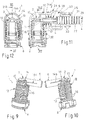
- the connection sections 6, 8 are connected via a transition section 10, which has an inner, only in Fig. 8 . 11 and 12 has recognizable flow channel 11.
- the connector piece 2 may also have any other, different from the illustrated examples embodiment, for.
- a T-piece or manifold with three or more terminal sections as a straight through connector, as an angle connector (eg., V-piece) with any, from right angles (90 °) deviating connection axis angle or the like.
- the connector piece 2 at least in the region of the transition section 10, has electrical heating means 12 in an arrangement surrounding the flow channel 11 radially or circumferentially.
- the line connector 1 according to the invention is particularly suitable for lines in motor vehicles for the guidance of gefriergefährdeten media, such as water or urea in particular.
- the term "transition section" 10 is to be understood as the area of the line connector 1 or of the connector piece 2, which is still “exposed” after connection of lines (4) and / or to an aggregate and therefore can be provided with heating means 12.
- At least one electrical heating wire 14 may be provided in an arrangement extending at least over the area of the transition section 10 with a substantially uniform area distribution. How to do this from the Fig. 1, 2 4 to 7, the connector piece 2 on the outside certain shape elements for guiding and fixing the externally applied heating wire 14.
- Outwardly projecting lugs 16 or ribs and / or-for example groove-shaped depressions 18 (FIG. Fig. 4 ) be provided.
- the heating wire 14 may have a meandering or serpentine course, for example, to avoid a coil effect during current flow; see. in particular Fig.
- the heating wire 14 and the connector piece 2 outside wrapped coil-like, see 10 to 12 , In Fig. 4 this is by a corresponding, here z. B. helical course of the groove-like depressions 18 indicated.
- a second, unrecognizable winding coil enclosing the flow channel in the interior region of the connector piece 2 such that an induction into the inner winding coil takes place through a flow of current through the outer heating wire 14.
- the externally applied heating wire 14 may be covered with a, for example, a powder coating or the like, existing insulating coating. It can also be a dip coating. Due to the insulating coating of the heating wire 14 can be carried out even without their own isolation.
- the heating wire 14 may also be embedded (molded) in the material of the plastic connector piece 2. This is on Fig. 8 referenced, after which a piece of pipe 20 is wrapped with the heating wire 14 and placed in an injection mold. The pipe section 20 provided with the heating wire 14 can then be overmoulded with plastic in any manner. The ends of the winding wire 14 are led to the outside to create a voltage can.
- the pipe section 20 may be made of plastic, but also of metal, in order to achieve a good heat conduction inwards into the flow channel 11.
- a non-illustrated planar heating element for example be provided in the form of a glued foil or printed Schuleiterbahnen.
- heating means 12 and the material of the connector piece 2 itself may be formed electrically conductive.
- the plastic material may have certain fillers to increase the thermal conductivity.
- Suitable fillers are particles of aluminum, Al 2 O 3 , glass and / or carbon fibers.
- the connector piece 2 may be enclosed by an outer encapsulation.
- indicated embodiment may be a two-part, two symmetrical housing halves 24a, 24b in the form of half-shells (see also FIGS. 11 and 12 ) existing outer housing 24, of which in Fig. 7 only one housing half 24a is shown.
- the housing halves (24a, 24b) can advantageously be connected to one another via complementary latching means 26.
- the entire connector piece 2 it is also possible to encapsulate the entire connector piece 2 as an encapsulation with an outer housing.
- a so-called shrink tube, fabric tube or the like may be provided as encapsulation.
- an air volume can be enclosed between this and the connector piece, whereby a good heat distribution, but also a thermal insulation is achieved to the outside.
- the outer coating or the encapsulation can bring about heat insulation to the outside.
- the wire ends are preferably fastened via snap-in connections so that they protrude outward for the purpose of contacting.
- the heating wire 14 runs according to Fig. 9 starting from a first, in the region of the outer surface of the connecting portion 6 arranged wire end 14a helically over the region of the transition section 10 and then according to Fig. 10 axially back, so that a second wire end 14b also lies in the region of the outer surface of the connecting portion 6, preferably approximately diametrically opposite the other wire end 14a.
- the wire ends 14a, 14b can be electrically connected to connecting conductors or, advantageously, to heating conductors of the media line 4.
- the heating wire 14 via z. B. helical heating conductor of the media line 4 are supplied with electrical power (voltage, current).
- the heating means 12 may be designed with a power of 3 to 20 watts and the heating wire 14 with a length of, for example, up to 200 mm.
- a power quotient in the range of 1 to 15 watts / cm 3 is appropriate.
- the heating wire 14 may be formed with a negative temperature coefficient (NTC) or a positive temperature coefficient (PTC).
- NTC negative temperature coefficient
- PTC positive temperature coefficient
- a supply voltage in the order of 10 to a maximum of 14 volts is appropriate.
- connection section 6 can be used as a connection pin for the direct attachment of a media line 4 (see, for this, the embodiments according to FIGS Fig. 1, 2, 4 and 5 ) or as a plug-in socket insertable plug shank ( Fig. 3 and 6 ) be formed.
- the Anschlußabscnitt 6 is formed as a hollow cylindrical receptacle for direct insertion of the media line.
- the media line 4 is firmly bonded in the connection section 6.
- the connection section 6 For welding by means of a laser beam, the connection section 6 at least partially consists of a laser-transparent material.
- connection section 8 this can also be designed as a plug-in socket for receiving a plug shank.
- any means can be provided for, in particular, releasable locking of the plug connection parts. This is exemplified on FIGS. 11 and 12 directed.
- Fig. 7 and also out Fig. 11 results, it may be particularly advantageous in combination with the encapsulation, in particular in the embodiment as an outer housing 24, and in the case of a self-heated media line 4, to provide the media line 4 with an additional enclosure 27, for example as shown in the form of a Line 4 enclosing corrugated pipe.
- the sheath 27 serves for mechanical protection and thermal insulation for at least one heating conductor 29 extending helically around the media line 4.
- the sheath 27 extends into the outer housing 24 and ends shortly before the connection section 6 extended chamber 28 for receiving electrical connections, not shown, between the Schudrahtenden 14 a, b and the ends of the heating element 23 of the media line 4 have.
- the outer housing 24 has in the introduction region of the sheath 27, the corrugated pipe, on its inner wall encircling ribs 25 which project into the wave troughs 31 of the corrugated pipe. According to the invention, a positive connection between the outer housing 24 and the enclosure 27 is formed. Moreover, in Fig. 7 it can be seen that also a positive connection between the outer housing 24 and the connector piece 2 is present. For this purpose, the outer housing 24 in the region of the connecting portion 8 of the connector piece 2, an inner groove 35 into which an annular collar 36 of the connector piece 2 protrudes.
- the housing halves 24a, b of the outer housing 24 via external, z. B. on the type of clamps, tension wires or spring clips trained holding elements 30 may be connected.
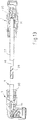
- the present invention also includes a prefabricated media conduit as shown in FIG Fig. 13 is shown.
- This prefabricated media line consists of an inner pipe 4a with a heat conductor 29 arranged on the circumference, as already described in US Pat Fig. 7 is shown.
- the pipe 4a with the heating element 29 is enclosed by an outer casing 27.
- This outer envelope 27 is preferably made as a corrugated tube. This may be a corrugated or corrugated corrugated tube.
- At the two ends of the thus formed media line 4 are each line connector, as to the Fig. 1 to 10 explained, connected.
- one end is a line connector 1, which is designed as an angle plug, attached, and at the other end is a straighter Plug connection provided as a line connector 1.
- the line connector 1 are each formed at the end as a sleeve part, but they can also be designed as a plug part.
- the sheath 27 is guided into the outer housing 24 of the line connector 1 and positively connected to the outer housing 24.
- the heating conductor 29 surrounding the pipe 4a is spirally wound around it and in particular is formed from two parallel wire windings 29a, b. These two wire windings 29a, b may consist of a continuous wire, wherein the two terminal ends are then present at the same end of the pipe. But they can also be formed from two separate wires.
- the heating conductor 29 is preferably wrapped with an adhesive tape and is thereby fixed on the pipe 4a. Alternatively, it may also be possible for the heating conductor 29 to be arranged on the pipeline 4a by means of an outer lacquer or adhesive layer.
- the density of the number of turns and / or the electrical resistance along the pipe 4a vary, so that in some sections different heating powers can be generated, for. B. in siphon areas or air flow acted upon areas of the media line, where there is an increased Gefrierne Trent the medium.
- the connector piece 2 present inside the line connector 1 may be connected to the pipe 4a via a plug connection, but it is also within the scope of the invention if the pipe 4a is connected to the connector piece 2 in a material-locking manner, for example by welding or gluing.
- a defined air gap is formed between the pipe 4a and the pipe covering 27.
- This can be achieved, for example, by the ring corrugation itself or else by spacers or the like arranged inside the corrugated tube.
- a potting compound 30 is introduced between the outer housing 24 of the line connector 1 and the connector piece 2, in particular in the connection region of the cable sheath 27 with the line connector 1, a potting compound 30 is introduced.
- the potting compound 30 on the one hand represents a mechanical protection, on the other hand, it can also serve to improve the IP degree of protection by sealing.
- the arrangement of the potting compound 30 is indicated by a dashed line.
- the arrangement of the potting compound 30 is indicated by a dashed line.
- the potting compound 30 is indicated by a dashed line.
- the potting compound 30 is indicated by a dashed line.
- the potting compound 30 is formed both in the transition region to the pipe 27 and as an outer sheath.
- a heat protection layer can, for. B. of a film, such as a metallized, heat radiation reflective film can be formed.
- a cushioning layer for example of sponge rubber or the like, can also be applied, in particular around the outer covering 27. It is also conceivable to arrange an additional outer thermal insulation layer.
- the arrangement of an outer sheath or a protective layer or reinforcement is in Fig. 14 Sectionally represented by the outer layer 27a in section. In Fig.
- FIG. 14 It is shown how the heating wires 14 of the line connector 1 and the heating line 29 of the pipe 4a can be electrically connected to each other.
- Fig. 14a is shown that in each case the heating wire of one of the line connector 1 is electrically connected in series with one of the winding wires of the wire windings 29a, b and the terminal ends of these two series circuits are routed to both line connectors 1 to the outside, where then a terminal of a power supply and / or a Continued connection can be made.
- R WST is the resistance of the heating wire winding 14 of a line connector 1, which is formed in the illustrated example as an angle plug
- R 1L the electrical resistance of one of the wires of the wire windings 29a, b surrounding the pipe 4a.
- R GST is the resistance of the heating wire 14 of the straight connector
- R 2L is the electrical resistance of the other winding wire of the wire winding 29a, b around the pipe 4a.
- the connections lying outside the line connector 1 are marked with A1 and A2 respectively.
- Fig. 14b is shown another interconnection.
- the heating wires 14 of the line connector 1 and the wire windings 29a, b are connected to the pipe 4a such that an electrical series connection of all wires is given.
- the terminal ends for connecting a voltage supply of the series connection are led out in the region of a line connector 1, and in this case the resistances of the individual wires are as in Fig. 14a characterized.
- only one outer line connection A1 is present.
- the size of each resistor can be from one embodiment of a prefabricated line according to the invention to another in each case vary and depends on the respective desired heating power.
- a further embodiment may be to arrange a further winding in the pipe end region of the pipe 4a to the circumferential winding 14 of the heating wire to provide additional wire length available. As a result, the possibility is created to pull out of the pipe end when contacting wire.
- a heatable media line according to the invention comprises the inner pipe 4a and an electrical heating element 40 arranged on the surface thereof.
- a protective jacket 41 can be applied circumferentially around the applied electrical heating element 40.
- the pipe 4a is advantageously made of plastic.
- the outer protective jacket 41 can be formed from an adhesive tape winding or from an extrusion layer or a heat shrinkable tube made of plastic and forms an external protection against damage and moisture. But it would also be a corresponding coating on the outwardly facing surface of the heating element 40 is possible.
- the heatable media line is preferably surrounded by a corrugated tube or a protective tube or a protective sheath, possibly with the inclusion of a circumferential air gap.
- the heating element 40 is designed as a surface heating element 43.
- This surface heating element 43 is strip-shaped and, as in the Fig. 16 is shown extending in the longitudinal direction of the pipe 4a with its longitudinal edges 46 overlapping around the pipe 4a. Alternatively, the longitudinal edges 46 may abut one another.
- Fig. 18 it is shown that the strip-shaped mecanicnheizelement 43 is wound spirally around the pipe 4a. It is either possible to choose an overlapping version of the helical winding as shown, or but a winding, wherein the longitudinal edges 46 of the strip-shaped mecanicnfilterianas 43 abut each other.
- the surface heating element 43 consists of a support 47 on which electrical heating conductors 48 are fixed.
- the electrical heating conductors 48 are connected in an electrically conductive manner to contact conductors 49 arranged on the carrier 47.
- it is a carrier 47 made of a textile nonwoven material, a knitted fabric or a fabric.
- it is also possible to form the carrier 47 from a plastic foam or from a combination of the above materials.
- the electrical heating conductors 48 are wave-shaped or meander-shaped and / or mesh-shaped laid on the carrier 47.
- the electrical heating conductors 48 are made of carbon fibers.
- the use of carbon fibers to make the electrical conductors brings the benefits of very high tensile strength with the lowest weight and good electrical conductivity; Furthermore, this transparency is given to X-rays, which is advantageous in control investigations. In addition, a resistance to chemicals and a high temperature resistance is ensured. In addition, carbon fibers are easy to process.
- the electrical heating conductors 48 are distributed uniformly over the entire surface of the surface heating element 43 in particular. Expediently, the main extension direction X of the electrical heating conductor 48 extends in the transverse direction of the strip-shaped carrier 47.
- the contact conductors 49 which may likewise consist of carbon fibers or else of metallic material, can run in a straight line and / or wave-like manner.
- a plurality of parallel contact conductors 49 are laid, as in Fig. 17 is shown.
- the contact conductors 49 run transversely, in particular perpendicular to the main extension direction X of the electrical heating conductor 48.
- the contact conductors 49 are respectively arranged at both end regions of the heating conductors 48 and in the region of the two longitudinal edges 46 of the carrier 47.
- the heating conductors 48 and the contact conductors 49 are fixed by stitching by means of textile sewing threads 51 on the carrier 47. In this case, the sewing direction Y of the sewing threads 51 in the main extension direction X of the heating conductors 48 runs.
- the textile carrier is formed freely only in a partial region, in particular in an overlap region 53 heating conductor. This ensures that a uniform heat output over the entire length of the pipe is available. It is also possible to form the overlapping area 53 at both longitudinal edges of the carrier 47.
- the support 47 is advantageously coated on its side facing away from the heating conductors 48 back with a temperature-resistant pressure-sensitive adhesive 54, whereby an intimate contact of the foundednfilettis 43 is ensured on the surface of the pipe 4a, so that a good heat transfer is possible.
- the carrier 47 is moisture-repellent equipped.
- the electrical contact conductors 49 are preferably flexible and extend between the heating conductors 48 and the carrier 47. The contact conductors 49 are led out at both ends for a series connection of different lines or preferably only at one of the ends of the inventive line 1 by means of two connecting wires 52. It is also possible to lead out only one connection wire 52 at each of the two ends.
- the contact conductors 49 are incorporated in the textile carrier 47.
- the electrical heating conductors 48 can either be arranged running parallel to one another, but they can also be designed to overlap each other. By such an overlapping arrangement of the heating conductors 48 a uniform contacting of the heating conductors 48 over the entire surface and a uniform current distribution is achieved, so that even with a single fraction of a Schuleiterabiteses thereby no significant impairment of the heating power occurs.
- a plurality of parallel contact conductors 49 are present, wherein also a wave-shaped arrangement is possible or even a mesh-like composite of the contact conductor 49 may be present, a secure contact with the heating conductors 48 is also possible.
- the invention is defined only by the following claims.
Landscapes
- Engineering & Computer Science (AREA)
- General Engineering & Computer Science (AREA)
- Mechanical Engineering (AREA)
- Pipe Accessories (AREA)
- Resistance Heating (AREA)
- Communication Cables (AREA)
- Addition Polymer Or Copolymer, Post-Treatments, Or Chemical Modifications (AREA)
- Feeding And Controlling Fuel (AREA)
Claims (13)
- Conduite de fluides (1) confectionnée à chauffage électrique, constituée d'au moins une conduite tubulaire (4a) munie d'un conducteur chauffant (29) disposé à sa périphérie et d'au moins un raccord de conduite (1) chauffant fixé à une extrémité de conduite tubulaire de la conduite tubulaire (4a), dans laquelle le raccord de conduite (1) est constitué d'une pièce de connexion (2) réalisée sous la forme d'une partie moulée en matière plastique d'un seul tenant comportant une section de raccordement (6) reliée à la conduite tubulaire (4a), au moins une autre section de raccordement (8) destinée à être raccordée à une conduite de fluides ou à un groupe moteur ainsi qu'une section de transition (10) adjacente aux sections de raccordement (6, 8) et les reliant entre elles, comportant un canal d'écoulement intérieur (11), dans lequel une section de raccordement (8) est réalisée sous la forme d'une partie d'enfichage mâle destinée à une liaison par enfichage amovible et une section de raccordement (6) est réalisée sous la forme d'une partie d'enfichage femelle destinée à une liaison par enfichage de la conduite de fluides (4), dans lequel il est prévu au moins dans la zone de la section de transition (10) des moyens de chauffage électriques,
caractérisée en ce que le raccord de conduite (1) comporte, au moins dans la zone de la section de transition (10), des moyens de chauffage électriques (10) agencés de manière à entourer circonférentiellement le canal d'écoulement (11), dans lequel il est prévu, en tant que moyens de chauffage (12) du raccord de conduite (1), au moins un fil chauffant (14) agencé de manière à s'étendre avec une répartition bidimensionnelle sensiblement régulière au moins à travers la zone de la section de transition (10), et le fil chauffant (14) entoure la pièce de connexion de manière enroulée sous la forme d'une bobine extérieure, dans lequel la section de raccordement (6) reliée à la conduite tubulaire (4a) est réalisée sous la forme d'un logement cylindrique creux permettant d'insérer directement l'extrémité de la conduite tubulaire (4a), dans lequel la conduite tubulaire (4a) est fixée par soudage avec complémentarité de matériau et la section de raccordement (6) est constituée au moins par zones d'un matériau transparent à des faisceaux laser de manière à ce que la conduite tubulaire (4a) soit fixée par soudage au moyen d'un faisceau laser, et la pièce de connexion (2) est entourée par une encapsulation extérieure (24) et l'encapsulation (24) est également réalisée de manière à entourer une extrémité de la conduite tubulaire (4a) et une extrémité d'une enveloppe de conduite (27) et le conducteur chauffant (29) entoure en spirale la conduite tubulaire (4a) et est constitué de deux enroulements de fil (29a, b) s'étendant parallèlement. - Conduite de fluides confectionnée selon la revendication 1,
caractérisée en ce que, dans la zone intérieure, il est prévu au moins une autre bobine d'enroulement disposée dans la zone du canal d'écoulement (11) de telle manière qu'une induction se produise dans la bobine d'enroulement intérieure par passage d'un courant à travers le fil chauffant (14) extérieur afin de produire de la chaleur. - Conduite de fluides confectionnée selon la revendication 1 ou 2,
caractérisée en ce que la pièce de connexion (2) comporte des éléments de formage (16, 18) permettant de guider et de fixer le fil chauffant (14) extérieur mis en place. - Conduite de fluides confectionnée selon l'une des revendications 1 à 3,
caractérisée en ce que l'encapsulation (24) est réalisée de manière à présenter une plus faible conductivité thermique à des fins d'isolation thermique, dans lequel l'encapsulation (24) est réalisée sous la forme d'un boîtier extérieur constitué de deux moitiés de boîtier symétriques qui forment deux demi-coques du boîtier extérieur. - Conduite de fluides confectionnée selon la revendication 4,
caractérisée en ce qu'un volume d'air est enfermé à des fins de répartition thermique et d'isolation thermique entre l'encapsulation (24) et la pièce de connexion (2). - Conduite de fluides confectionnée selon l'une des revendications 1 à 5,
caractérisée en ce que l'encapsulation (24) est reliée par complémentarité de forme à la pièce de connexion (2), dans lequel il est notamment prévu dans le boîtier extérieur des ouvertures (33) servant à extraire des fils de connexion destinés au raccordement des moyens chauffants (12, 14), dans lequel lesdites ouvertures (33) se situent notamment dans le plan de division du boîtier extérieur (24). - Conduite de fluides confectionnée selon l'une des revendications 1 à 6,
caractérisée en ce que l'enveloppe (27), notamment sous la forme d'un tube ondulé, entoure la conduite tubulaire (4a) comportant le conducteur chauffant (29) et est inséré dans le boîtier extérieur (24) du raccord de conduite (1) et est relié à celui-ci par complémentarité de forme. - Conduite de fluides confectionnée selon l'une des revendications 1 à 7,
caractérisée en ce que le conducteur chauffant (29) est fixé à la conduite tubulaire (4a) au moyen d'un ruban adhésif. - Conduite de fluides confectionnée selon l'une des revendications 1 à 8,
caractérisée en ce qu'une masse de coulée est introduite entre le boîtier extérieur (24) et la pièce de connexion (2) et en particulier dans la zone de connexion de l'enveloppe de conduite (27), à l'intérieur du boîtier extérieur (24). - Conduite de fluides confectionnée selon l'une des revendications 1 à 9,
caractérisée en ce qu'à chaque extrémité de la conduite tubulaire (4a) chauffante est raccordé un raccord de conduite (1) et en ce que la conduite tubulaire (4a) est enroulée avec deux enroulements de fil (29a, b) s'étendant parallèlement. - Conduite de fluides confectionnée selon la revendication 10,
caractérisée en ce que les fils chauffants (14) du raccord de conduite (1) et les enrouements de fil (29a, b) de la conduite tubulaire (4a) sont reliés de manière à former un circuit série électrique, dans lequel les extrémités de raccordement sont guidées vers l'extérieur pour raccorder une alimentation en tension extérieure du circuit série dans la zone d'un raccord de conduite (1). - Conduite de fluides confectionnée selon la revendication 10,
caractérisée en ce que le fil chauffant (14) de l'un des raccords de conduite (1) est respectivement connecté électriquement à l'un des enroulements de fil (29a, b) de la conduite tubulaire (4a), dans laquelle les extrémités de raccordement des deux circuits série sont respectivement guidées vers l'extérieur sur l'un des deux raccords de conduite (1) pour raccorder une alimentation en tension et/ou pour établir une autre connexion. - Conduite de fluides confectionnée selon l'une des revendications 1 à 12,
caractérisée en ce que le conducteur chauffant (29) est disposé ou réalisé le long de la conduite tubulaire (4a) de manière à ce que sa résistance électrique varie par sections afin de générer des puissances de chauffage différentes par sections.
Priority Applications (1)
| Application Number | Priority Date | Filing Date | Title |
|---|---|---|---|
| PL11168387T PL2363627T3 (pl) | 2007-04-26 | 2008-03-19 | Złączka przewodu mediów |
Applications Claiming Priority (5)
| Application Number | Priority Date | Filing Date | Title |
|---|---|---|---|
| DE202007006115 | 2007-04-26 | ||
| DE202007009588U DE202007009588U1 (de) | 2007-04-26 | 2007-07-09 | Leitungsverbinder für Medienleitungen |
| DE102007040786 | 2007-08-28 | ||
| DE202008003365U DE202008003365U1 (de) | 2008-03-10 | 2008-03-10 | Beheizbare Fluidleitung |
| EP08735439.5A EP2137449B2 (fr) | 2007-04-26 | 2008-03-19 | Raccord pour conduites d'acheminement de substances |
Related Parent Applications (3)
| Application Number | Title | Priority Date | Filing Date |
|---|---|---|---|
| EP08735439.5 Division | 2008-03-19 | ||
| EP08735439.5A Division-Into EP2137449B2 (fr) | 2007-04-26 | 2008-03-19 | Raccord pour conduites d'acheminement de substances |
| EP08735439.5A Division EP2137449B2 (fr) | 2007-04-26 | 2008-03-19 | Raccord pour conduites d'acheminement de substances |
Publications (2)
| Publication Number | Publication Date |
|---|---|
| EP2363627A1 EP2363627A1 (fr) | 2011-09-07 |
| EP2363627B1 true EP2363627B1 (fr) | 2018-05-09 |
Family
ID=39617542
Family Applications (2)
| Application Number | Title | Priority Date | Filing Date |
|---|---|---|---|
| EP08735439.5A Active EP2137449B2 (fr) | 2007-04-26 | 2008-03-19 | Raccord pour conduites d'acheminement de substances |
| EP11168387.6A Active EP2363627B1 (fr) | 2007-04-26 | 2008-03-19 | Liaison câblée pour tansfer de fluides |
Family Applications Before (1)
| Application Number | Title | Priority Date | Filing Date |
|---|---|---|---|
| EP08735439.5A Active EP2137449B2 (fr) | 2007-04-26 | 2008-03-19 | Raccord pour conduites d'acheminement de substances |
Country Status (7)
| Country | Link |
|---|---|
| US (2) | US8526801B2 (fr) |
| EP (2) | EP2137449B2 (fr) |
| CN (1) | CN103644421B (fr) |
| AT (1) | ATE513158T1 (fr) |
| ES (1) | ES2682301T3 (fr) |
| PL (2) | PL2363627T3 (fr) |
| WO (1) | WO2008131993A1 (fr) |
Families Citing this family (61)
| Publication number | Priority date | Publication date | Assignee | Title |
|---|---|---|---|---|
| ES2682301T3 (es) * | 2007-04-26 | 2018-09-19 | Voss Automotive Gmbh | Conector de tubería para tuberías de fluidos |
| US9651185B2 (en) | 2008-03-19 | 2017-05-16 | Voss Automotive Gmbh | Line connector for media lines |
| DE202009003807U1 (de) * | 2009-03-20 | 2010-08-12 | Voss Automotive Gmbh | Elektrisches Heizsystem für ein Fluid-Leitungssystem |
| DE202009012230U1 (de) † | 2009-06-23 | 2010-11-04 | Voss Automotive Gmbh | Elektrisch beheizbare Medienleitung sowie Leitungsverbinder |
| CN102597592B (zh) * | 2009-06-24 | 2016-04-13 | 福士汽车配套部件责任有限公司 | 能够电加热的介质导管以及导管连接器 |
| DE102009044404A1 (de) | 2009-11-03 | 2011-05-05 | Contitech Techno-Chemie Gmbh | System zum Verbinden von Schlauchleitungen |
| BR112012016331A2 (pt) | 2010-01-08 | 2018-04-03 | Parker Hannifin Corp | montagem de mangueira eletricamente aquecida para sistemas de redução catalítica seletiva (scr) |
| WO2011139898A1 (fr) | 2010-04-29 | 2011-11-10 | Parker-Hannifin Corporation | Ensemble tubage et raccord chauffé à l'électricité et destiné à des systèmes de réduction catalytique sélective (scr) |
| DE102010032189B4 (de) | 2010-07-23 | 2024-07-25 | Voss Automotive Gmbh | Verfahren zum Herstellen einer beheizbaren Medienleitung und beheizbare Medienleitung, hergestellt nach dem Verfahren |
| DE102010032188A1 (de) | 2010-07-23 | 2012-01-26 | Voss Automotive Gmbh | Beheizbare Medienleitung |
| DE102010053737A1 (de) * | 2010-12-08 | 2012-06-14 | Voss Automotive Gmbh | Beheizbare Fluidleitung, deren Verwendung sowie Verfahren zu ihrer Herstellung |
| DE102010055520B4 (de) | 2010-12-22 | 2023-10-05 | Voss Automotive Gmbh | Konfektionierte Medienleitung sowie Verwendung in einem SCR-Katalysator-System |
| US9435477B2 (en) * | 2011-03-22 | 2016-09-06 | Sami Mustafa | Creating thermal uniformity in heated piping and weldment systems |
| DE202011106751U1 (de) * | 2011-10-14 | 2013-01-18 | Voss Automotive Gmbh | Zumindest teilweise beheizbarer Leitungsverbinder für eine beheizbare Medienleitung sowie konfektionierte Medienleitung mit einem solchen Leitungsverbinder |
| WO2013053478A1 (fr) * | 2011-10-14 | 2013-04-18 | Voss Automotive Gmbh | Connecteur au moins partiellement chauffable pour une conduite chauffable destinée à un milieu, et conduite destinée à un milieu confectionnée et dotée d'un tel connecteur |
| DE102011120357A1 (de) * | 2011-12-07 | 2013-06-13 | Voss Automotive Gmbh | Konfektionierte beheizbare Medienleitung mit einer Medienleitung mit zumindest zwei auf deren Außenseite angeordneten Heizelementen und Verfahren zu ihrer Herstellung |
| CA2865495C (fr) * | 2012-02-28 | 2019-06-11 | Norma U.S. Holding Llc | Ensemble et support de capteur de systeme de reduction catalytique selective (scr) d'automobile |
| DE202012102189U1 (de) * | 2012-06-14 | 2013-09-16 | Rehau Ag + Co | Schlauchleitungssystem, insbesondere zum Transport von in Kfz-Brennstoffzellenanlagen entstehendem Reaktionswasser |
| DE202013103243U1 (de) | 2013-07-19 | 2014-10-20 | Rehau Ag + Co | Medienleitung, insbesondere zum Transport einer Harnstoff-Wasser-Lösung |
| DE102013220142A1 (de) * | 2013-10-04 | 2015-04-09 | Bruker Biospin Gmbh | Magnetspulenanordnung umfassend einen HTSL-Bandleiter und einen LTS-Draht, die einen Joint ausbilden |
| FR3013291B1 (fr) * | 2013-11-21 | 2017-07-14 | Valeo Systemes Dessuyage | Interface hydraulique chauffante pour un systeme d'approvisionnement et/ou de distribution en liquide lave glace de vehicule automobile |
| FR3015171B1 (fr) | 2013-12-12 | 2016-01-01 | Total Sa | Procede pour former une connexion electrique |
| FR3015172B1 (fr) | 2013-12-12 | 2019-05-10 | Total Sa | Dispositif de chauffage electrique |
| FR3014737A1 (fr) | 2013-12-12 | 2015-06-19 | Total Sa | Bande composite et procedes pour former une jonction entre deux conduites |
| JP6297325B2 (ja) * | 2013-12-20 | 2018-03-20 | 日野自動車株式会社 | 車両の尿素水配管システム |
| DE112014006048T5 (de) * | 2013-12-25 | 2016-09-08 | Nitta Corporation | Verbinderabdeckung |
| DE102014003425A1 (de) | 2014-03-03 | 2015-09-03 | Mtu Friedrichshafen Gmbh | Verbrennungskraftmaschine mit Reduktionsmittelverteilerblock und Volumenausgleichs- und Dichtelement dafür |
| DE102014012851A1 (de) | 2014-09-03 | 2016-03-03 | Voss Automotive Gmbh | Leitungsverbinder sowie Verfahren zum Versehen eines formelementfreien Leitungsverbinders mit zumindest einer Heizlitze oder einem Heizdraht |
| DE202014105908U1 (de) * | 2014-12-06 | 2015-01-14 | Eugen Forschner Gmbh | Beheizungssystem für eine fluidführende Leitung |
| DE102014018371A1 (de) * | 2014-12-15 | 2016-06-16 | Voss Automotive Gmbh | Beheizbare Medienleitung sowie Verfahren zum Herstellen einer beheizbaren Medienleitung |
| US10591182B2 (en) * | 2015-03-31 | 2020-03-17 | Lam Research Corporation | Apparatus for thermal control of tubing assembly and associated methods |
| US10139132B2 (en) * | 2015-03-31 | 2018-11-27 | Lam Research Corporation | Apparatus for thermal control of tubing assembly and associated methods |
| DE102015104947B4 (de) * | 2015-03-31 | 2017-10-19 | Voss Automotive Gmbh | Beheizte Medienleitung |
| DE202015002874U1 (de) | 2015-04-20 | 2016-07-22 | A.RAYMOND et Cie. SCS | Anschlussstück zum Verbinden eines oberflächenstrukturierten, mindestens eine Vertiefung in seiner Oberfläche aufweisenden Endes eines sich entlang einer Längsrichtung erstreckenden Schlauchs mit einem Fluidauslass; System mit einem solchen Anschlussstück und Verwendung für ein solches Anschlussstück |
| KR102581435B1 (ko) * | 2015-07-14 | 2023-09-20 | 램 리써치 코포레이션 | 튜빙 어셈블리의 열 제어를 위한 장치 및 연관된 방법들 |
| US20170023164A1 (en) * | 2015-07-24 | 2017-01-26 | Eichenauer Heizelemente Gmbh & Co. Kg | Pipe connector and method for manufacturing a pipe connector |
| JP6549455B2 (ja) * | 2015-09-24 | 2019-07-24 | 住友建機株式会社 | ショベル |
| DE102016109051A1 (de) * | 2015-10-21 | 2017-04-27 | Voss Automotive Gmbh | Steckverbinder für Medienleitungen |
| WO2017100672A1 (fr) | 2015-12-10 | 2017-06-15 | Saint-Gobain Performance Plastics Corporation | Coupleur de transport de fluide |
| EP3026318B1 (fr) | 2015-12-23 | 2018-02-14 | TI Automotive (Fuldabrück) GmbH | Connecteur comprenant une aide au montage et procede de fabrication dudit connecteur |
| US10750578B2 (en) * | 2016-01-29 | 2020-08-18 | Voss Automotive Gmbh | Assembled media line and contour shaped cap device |
| EP3211190B1 (fr) * | 2016-02-23 | 2019-04-17 | TI Automotive (Fuldabrück) GmbH | Systeme de connexion dote d'au moins un connecteur et au moins une conduite de fluide |
| DE102016111194A1 (de) * | 2016-06-20 | 2017-12-21 | Voss Automotive Gmbh | Kupplungsteil für einen Steckverbinder zur Herstellung von Schlauch- und/oder Rohrverbindungen und Steckverbinder mit einem derartigen Kupplungsteil |
| US20180051605A1 (en) * | 2016-08-16 | 2018-02-22 | Caterpillar Inc. | Conduit for maintaining temperature of fluid |
| US10396500B2 (en) | 2016-08-31 | 2019-08-27 | Norma U.S. Holding Llc | Electrically conductive conduit assembly |
| DE102017203283A1 (de) * | 2017-03-01 | 2018-09-06 | Robert Bosch Gmbh | Heizeinrichtung |
| EP3382255B1 (fr) | 2017-03-29 | 2019-07-03 | TI Automotive (Fuldabrück) GmbH | Conduite comprenant un raccord et procédé de fonctionnement de ladite conduite |
| EP3382254B1 (fr) * | 2017-03-29 | 2020-06-03 | TI Automotive (Fuldabrück) GmbH | Conduite chauffée comprenant une prise et son procédé de fonctionnement |
| CN107482362B (zh) * | 2017-07-31 | 2023-08-29 | 深圳市沃尔新能源电气科技股份有限公司 | 电缆连接器 |
| US10590825B2 (en) | 2017-11-27 | 2020-03-17 | Voss Automotive Gmbh | Line connector with integrated sensor for measurement of urea solutions |
| DE102017127936A1 (de) * | 2017-11-27 | 2019-05-29 | Voss Automotive Gmbh | Leitungsverbinder mit integriertem Sensor zur Messung von Harnstoff-Lösungen |
| US10508577B2 (en) | 2017-11-27 | 2019-12-17 | Voss Automotive Gmbh | Line connector with integrated sensor for measurement of urea solutions |
| DE102018103571A1 (de) * | 2018-02-16 | 2019-08-22 | Voss Automotive Gmbh | Verbindungsanordnung zum Verbinden von beheizbaren Fluidleitungen |
| EP3560674A1 (fr) | 2018-05-17 | 2019-10-30 | Brita GmbH | Conduit destiné à un distributeur de liquide, son procédé de fabrication et son utilisation |
| CN108679826B (zh) * | 2018-06-07 | 2024-09-03 | 佛山市顺德区腾芯电子科技有限公司 | 一种用途可转换的多功能加热模组及其转换方法 |
| FR3088676B1 (fr) * | 2018-11-15 | 2020-12-11 | Continental Automotive France | Module de dosage d'un agent reducteur avec pont thermique elastique |
| DE102020108149A1 (de) * | 2019-10-17 | 2021-04-22 | Voss Automotive Gmbh | Verbinder für Fluidleitungen |
| FR3106365B1 (fr) | 2020-01-20 | 2022-10-14 | Hutchinson | Dispositif de raccordement fluidique et de chauffage de fluide |
| FR3106390B1 (fr) | 2020-01-20 | 2021-12-10 | Hutchinson | Coque chauffante pour raccord trois voies |
| DE102020106220B3 (de) | 2020-03-06 | 2021-08-19 | Eugen Forschner Gmbh | Heizschlauch-Wellrohr-Verbindung |
| DE102022203692A1 (de) * | 2022-04-12 | 2023-10-12 | Contitech Techno-Chemie Gmbh | Beheizbare Fluidleitung mit induktiver Schnittstelle |
Citations (2)
| Publication number | Priority date | Publication date | Assignee | Title |
|---|---|---|---|---|
| US5933574A (en) * | 1998-02-09 | 1999-08-03 | Avansino; Gary L. | Heated fluid conduit |
| WO2005124219A1 (fr) * | 2004-06-15 | 2005-12-29 | Volvo Lastvagnar Ab | Raccord chauffant electrique et tubulure a gaine chauffante en etant munie |
Family Cites Families (59)
| Publication number | Priority date | Publication date | Assignee | Title |
|---|---|---|---|---|
| US2793280A (en) † | 1954-10-06 | 1957-05-21 | Waterbury Pressed Metal Co | Electrically heated liquid connection unit |
| US3932727A (en) * | 1973-12-11 | 1976-01-13 | Cecil Wayne True | Electrically heated riser pipe for a fluid supply system |
| JPS51123223U (fr) | 1975-04-02 | 1976-10-06 | ||
| JPS51123223A (en) † | 1975-04-21 | 1976-10-27 | Fuji Photo Film Co Ltd | Process for producing condensation products |
| US4069409A (en) † | 1975-07-28 | 1978-01-17 | Noland Wayne B | Electrically heated fluid coupling apparatus |
| US4063790A (en) | 1976-10-15 | 1977-12-20 | Dayco Corporation | Fluid conduit assembly |
| FR2372324A1 (fr) | 1976-11-26 | 1978-06-23 | Gargatte Jean | Perfectionnements aux carburateurs |
| JPS572535Y2 (fr) † | 1977-09-16 | 1982-01-16 | ||
| DE2804818C2 (de) * | 1978-02-04 | 1986-12-11 | Fritz Eichenauer GmbH & Co KG, 6744 Kandel | Elektrische Heizeinrichtung |
| US4447707A (en) * | 1981-12-22 | 1984-05-08 | Nordson Corporation | Electrically heated multi-section hose having electrically heated hose joints |
| US4616894A (en) * | 1985-01-14 | 1986-10-14 | Nordson Corporation | Electrical connector for hot melt hose unit and gun |
| US4644134A (en) * | 1985-09-25 | 1987-02-17 | Nordson Corporation | Electrically heated hose having corrugated plastic cover |
| DE3536751A1 (de) † | 1985-10-15 | 1987-04-16 | Alligator Ventilfab Gmbh | Heizvorrichtung fuer waschfluessigkeit in scheibenwaschanlagen von fahrzeugen |
| DE8704903U1 (de) † | 1987-04-02 | 1987-05-27 | REHAU AG + Co, 8673 Rehau | Verbindungsstück für beheizbare Schläuche |
| DE8900869U1 (de) | 1989-01-26 | 1989-03-09 | REHAU AG + Co, 8673 Rehau | Wärmeisoliertes Verbindungs- oder Verteilerstück für beheizbare Schläuche |
| DE4138426A1 (de) * | 1991-11-22 | 1993-05-27 | Kanthal Gmbh | Elektrisches heizelement eines russfilters |
| US5544275A (en) † | 1993-03-17 | 1996-08-06 | Applied Materials, Inc. | Electrically heated fluid carrying conduit having integrated heating elements and electrical conductors |
| DE69603808T2 (de) * | 1995-09-20 | 2000-01-27 | Luciano Scarzella | Isolierung und/oder Heiz- und/oder Kühlsystem mit vorgefertigten Elementen getrennt von den Rohren |
| US5832178A (en) * | 1996-06-25 | 1998-11-03 | Crafco, Incorporated | Hot melt mix applicator with electrically heated hose and wand with temperature-controlled electric generator |
| US5791377A (en) † | 1996-07-08 | 1998-08-11 | Yazaki Corporation | Electrically heated conduit |
| CA2181964C (fr) * | 1996-07-24 | 2007-02-20 | Chun Keung Mak | Buse de moulage par injection utilisant une clavette terminale de reperage, avec moyen d'etancheite |
| JPH1060959A (ja) * | 1996-08-23 | 1998-03-03 | Sekisui Plastics Co Ltd | ヒータ付配管 |
| US6062206A (en) | 1998-03-19 | 2000-05-16 | Phillips & Temro Industries Inc. | PCV heater and method for manufacturing same |
| CA2250599A1 (fr) * | 1998-10-16 | 2000-04-16 | Jobst Ulrich Gellert | Appareil et methode de fabrication d'une buse de moulage par injection avec col de pastille rapporte |
| CN2356208Y (zh) * | 1999-01-05 | 1999-12-29 | 秦杰民 | 管道电加热器 |
| DE19902431B4 (de) | 1999-01-22 | 2006-04-27 | Siemens Ag | Zwischenstück mit einem Anschluß von Waschflüssigkeitsleitungen einer Scheibenreinigungsanlage |
| DE10130362C2 (de) | 2001-06-23 | 2003-05-15 | Tyco Electronics Amp Gmbh | Elektrische Kontaktieranordnung |
| CA2457912C (fr) † | 2001-08-30 | 2011-09-20 | Cooper Technology Services, Llc. | Ensembles soupapes et tuyaux en pvc chauffes |
| US6617556B1 (en) * | 2002-04-18 | 2003-09-09 | Conocophillips Company | Method and apparatus for heating a submarine pipeline |
| ES2236398T3 (es) * | 2002-06-27 | 2005-07-16 | DAVID & BAADER DBK SPEZIALFABRIK ELEKTRISCHER APPARATE UND HEIZWIDERSTANDE GMBH | Dispositivo de calentamiento para un conducto y procedimiento de construccion. |
| DE10326894B3 (de) | 2003-06-14 | 2004-09-30 | Rasmussen Gmbh | Heizvorrichtung mit einer elektrischen Wärmequelle zum Erwärmen eines Fluids in einer Fluidleitung eines Kraftfahrzeugs |
| DE10340467B4 (de) † | 2003-09-03 | 2012-10-04 | Man Truck & Bus Ag | Vorrichtung zur Führung eines fließfähigen Mediums |
| CN101138053A (zh) * | 2003-10-20 | 2008-03-05 | 国际阻抗公司 | 一种铝管上的电阻膜 |
| JP2005193614A (ja) † | 2004-01-09 | 2005-07-21 | Ube Ind Ltd | パイプ形状品の接合方法 |
| DE502004000765D1 (de) | 2004-01-23 | 2006-07-27 | Dbk David & Baader Gmbh | Heizclip für eine Fluidleitung |
| SE528060C2 (sv) * | 2004-02-25 | 2006-08-22 | Volvo Lastvagnar Ab | Elektriskt uppvärmningsbart kablage |
| GB0503891D0 (en) | 2005-02-25 | 2005-04-06 | Allen Group Ltd | Electrically-heated pipes |
| DE202005004602U1 (de) | 2005-03-18 | 2005-07-14 | Eichenauer Heizelemente Gmbh & Co. Kg | Beheizte Flüssigkeitsleitung |
| EP1710484B1 (fr) * | 2005-04-05 | 2009-06-17 | DBK David + Baader GmbH | Dispositif de chauffage électrique d'un fluide dans un tuyau souple |
| DE202006003590U1 (de) * | 2005-04-14 | 2006-06-01 | Schlemmer Gmbh | Beheizbarer Wellschlauch |
| US7773867B2 (en) * | 2005-05-06 | 2010-08-10 | Illinois Tool Works Inc. | Hot melt adhesive hose assembly having redundant components |
| US20070036528A1 (en) * | 2005-07-29 | 2007-02-15 | William Ferrone | Heated hose electrical cord |
| EP1931906A1 (fr) | 2005-09-16 | 2008-06-18 | Dayco Fluid Technologies S.p.A. | Raccord de tuyauterie pour conduite chauffable de systeme de reduction catalytique selective |
| DE202005015966U1 (de) * | 2005-10-10 | 2007-02-15 | Voss Automotive Gmbh | Steckverbinder für Medienleitungen |
| DE102005050867A1 (de) † | 2005-10-24 | 2007-04-26 | Dbk David + Baader Gmbh | Beheizbarer Steckverbinder |
| SE529417C2 (sv) | 2005-12-22 | 2007-08-07 | Volvo Lastvagnar Ab | Ledningsnät för ett fordon |
| WO2007125572A1 (fr) | 2006-04-26 | 2007-11-08 | Nissan Diesel Motor Co., Ltd. | Composant de chauffage pour joint de tuyau |
| ES2682301T3 (es) * | 2007-04-26 | 2018-09-19 | Voss Automotive Gmbh | Conector de tubería para tuberías de fluidos |
| DE102008025299A1 (de) * | 2007-06-12 | 2008-12-18 | Contitech Schlauch Gmbh | Anschlussvorrichtung für medienführende, elektrisch beheizbare Schläuche |
| DE202007010502U1 (de) * | 2007-07-26 | 2008-11-27 | Voss Automotive Gmbh | Konfektionierte Medienleitung |
| DE202007013316U1 (de) * | 2007-09-21 | 2009-02-12 | Voss Automotive Gmbh | Anschlussvorrichtung für Medienleitungen |
| DE202007018089U1 (de) * | 2007-12-21 | 2009-05-07 | Voss Automotive Gmbh | Beheizbare Medienleitung |
| PL2222995T3 (pl) * | 2007-12-21 | 2015-04-30 | Voss Automotive Gmbh | Element połączeniowy przewodów dla przewodów dla mediów oraz zespolony przewód dla mediów z co najmniej jednym takim elementem połączeniowym przewodów |
| DE202008015289U1 (de) * | 2008-11-18 | 2010-04-08 | Voss Automotive Gmbh | Leitungsverbinder für Medienleitungen |
| DE202009012230U1 (de) * | 2009-06-23 | 2010-11-04 | Voss Automotive Gmbh | Elektrisch beheizbare Medienleitung sowie Leitungsverbinder |
| US8328549B2 (en) * | 2009-12-29 | 2012-12-11 | Synventive Molding Solutions, Inc. | Heating apparatus for fluid flow channel |
| JP2011196194A (ja) | 2010-03-17 | 2011-10-06 | Yanmar Co Ltd | 排気ガス浄化装置 |
| DE102010032189B4 (de) * | 2010-07-23 | 2024-07-25 | Voss Automotive Gmbh | Verfahren zum Herstellen einer beheizbaren Medienleitung und beheizbare Medienleitung, hergestellt nach dem Verfahren |
| DE102010055520B4 (de) * | 2010-12-22 | 2023-10-05 | Voss Automotive Gmbh | Konfektionierte Medienleitung sowie Verwendung in einem SCR-Katalysator-System |
-
2008
- 2008-03-19 ES ES11168387.6T patent/ES2682301T3/es active Active
- 2008-03-19 EP EP08735439.5A patent/EP2137449B2/fr active Active
- 2008-03-19 AT AT08735439T patent/ATE513158T1/de active
- 2008-03-19 WO PCT/EP2008/053295 patent/WO2008131993A1/fr not_active Ceased
- 2008-03-19 PL PL11168387T patent/PL2363627T3/pl unknown
- 2008-03-19 CN CN201310589022.1A patent/CN103644421B/zh active Active
- 2008-03-19 EP EP11168387.6A patent/EP2363627B1/fr active Active
- 2008-03-19 US US12/597,310 patent/US8526801B2/en active Active
- 2008-03-19 PL PL08735439T patent/PL2137449T5/pl unknown
-
2013
- 2013-08-15 US US13/967,837 patent/US9429259B2/en active Active
Patent Citations (2)
| Publication number | Priority date | Publication date | Assignee | Title |
|---|---|---|---|---|
| US5933574A (en) * | 1998-02-09 | 1999-08-03 | Avansino; Gary L. | Heated fluid conduit |
| WO2005124219A1 (fr) * | 2004-06-15 | 2005-12-29 | Volvo Lastvagnar Ab | Raccord chauffant electrique et tubulure a gaine chauffante en etant munie |
Also Published As
| Publication number | Publication date |
|---|---|
| US9429259B2 (en) | 2016-08-30 |
| EP2137449B2 (fr) | 2018-10-17 |
| WO2008131993A1 (fr) | 2008-11-06 |
| CN103644421B (zh) | 2016-11-02 |
| PL2363627T3 (pl) | 2018-10-31 |
| EP2137449B9 (fr) | 2012-01-18 |
| CN103644421A (zh) | 2014-03-19 |
| US20130336643A1 (en) | 2013-12-19 |
| US8526801B2 (en) | 2013-09-03 |
| EP2137449A1 (fr) | 2009-12-30 |
| PL2137449T3 (pl) | 2011-11-30 |
| EP2137449B1 (fr) | 2011-06-15 |
| ES2682301T3 (es) | 2018-09-19 |
| PL2137449T5 (pl) | 2019-03-29 |
| ATE513158T1 (de) | 2011-07-15 |
| EP2363627A1 (fr) | 2011-09-07 |
| US20100290764A1 (en) | 2010-11-18 |
Similar Documents
| Publication | Publication Date | Title |
|---|---|---|
| EP2137449B2 (fr) | Raccord pour conduites d'acheminement de substances | |
| EP1985908B1 (fr) | Liaison câblée pour tansfer de fluides | |
| DE102010032189B4 (de) | Verfahren zum Herstellen einer beheizbaren Medienleitung und beheizbare Medienleitung, hergestellt nach dem Verfahren | |
| EP2788692B1 (fr) | Conduite à fluide confectionnée, sous forme d'une conduite à fluide comportant au moins deux éléments de chauffe placés sur sa face externe, et procédé de production de ladite conduite | |
| EP2641006B1 (fr) | Conduite de fluides confectionnée à chauffage électrique et procédé de fabrication de ladite conduite | |
| DE202007009588U1 (de) | Leitungsverbinder für Medienleitungen | |
| EP2220419B1 (fr) | Conduit chauffable pour fluides | |
| EP2596275B2 (fr) | Conduite chauffable pour fluides | |
| EP2222995B1 (fr) | Raccord pour conduits pour fluides ainsi que conduit confectionné pour fluides présentant au moins un raccord pour conduits de ce type | |
| EP1519098B1 (fr) | Conduit de transport de fluide à chauffage électrique | |
| EP2766652B2 (fr) | Conduite de fluide pouvant être chauffée comprenant au moins une conduite de fluide présentant deux raccords de conduite | |
| WO2013053478A1 (fr) | Connecteur au moins partiellement chauffable pour une conduite chauffable destinée à un milieu, et conduite destinée à un milieu confectionnée et dotée d'un tel connecteur | |
| EP2788646B2 (fr) | Conduite à fluide confectionnée et procédé de confection d'une conduite à fluide pourvue d'éléments de chauffe internes | |
| DE102014018372B4 (de) | Konfektionierte beheizbare Medienleitung sowie Verfahren zu deren Herstellung | |
| DE202008007392U1 (de) | Fluidleitung und Leitungsverbinder zum Führen und Beheizen eines Mediums | |
| DE102016113493A1 (de) | Leitungsverbinder und Verfahren zum Herstellen eines Leitungsverbinders | |
| DE202007018086U1 (de) | Leitungsverbinder für Medienleitungen sowie konfektionierte Medienleitung mit mindestens einem solchen Leitungsverbinder | |
| DE102014005093A1 (de) | Konfektionierte beheizbare Medienleitung sowie Verfahren zu deren Herstellung | |
| DE202014103393U1 (de) | Verbinder und Verbinderaggregat aus Verbinder und Rohrleitung | |
| DE102011115890A1 (de) | Zumindest teilweise beheizbarer Leitungsverbinder für einebeheizbare Medienleitung sowie konfektionierte Medienleitung mit einem solchen Leitungsverbinder |
Legal Events
| Date | Code | Title | Description |
|---|---|---|---|
| PUAI | Public reference made under article 153(3) epc to a published international application that has entered the european phase |
Free format text: ORIGINAL CODE: 0009012 |
|
| AC | Divisional application: reference to earlier application |
Ref document number: 2137449 Country of ref document: EP Kind code of ref document: P |
|
| AK | Designated contracting states |
Kind code of ref document: A1 Designated state(s): AT BE BG CH CY CZ DE DK EE ES FI FR GB GR HR HU IE IS IT LI LT LU LV MC MT NL NO PL PT RO SE SI SK TR |
|
| 17P | Request for examination filed |
Effective date: 20110913 |
|
| 17Q | First examination report despatched |
Effective date: 20120913 |
|
| GRAP | Despatch of communication of intention to grant a patent |
Free format text: ORIGINAL CODE: EPIDOSNIGR1 |
|
| STAA | Information on the status of an ep patent application or granted ep patent |
Free format text: STATUS: GRANT OF PATENT IS INTENDED |
|
| INTG | Intention to grant announced |
Effective date: 20171213 |
|
| GRAS | Grant fee paid |
Free format text: ORIGINAL CODE: EPIDOSNIGR3 |
|
| GRAA | (expected) grant |
Free format text: ORIGINAL CODE: 0009210 |
|
| STAA | Information on the status of an ep patent application or granted ep patent |
Free format text: STATUS: THE PATENT HAS BEEN GRANTED |
|
| AC | Divisional application: reference to earlier application |
Ref document number: 2137449 Country of ref document: EP Kind code of ref document: P |
|
| AK | Designated contracting states |
Kind code of ref document: B1 Designated state(s): AT BE BG CH CY CZ DE DK EE ES FI FR GB GR HR HU IE IS IT LI LT LU LV MC MT NL NO PL PT RO SE SI SK TR |
|
| REG | Reference to a national code |
Ref country code: GB Ref legal event code: FG4D Free format text: NOT ENGLISH |
|
| REG | Reference to a national code |
Ref country code: CH Ref legal event code: EP Ref country code: AT Ref legal event code: REF Ref document number: 997894 Country of ref document: AT Kind code of ref document: T Effective date: 20180515 |
|
| REG | Reference to a national code |
Ref country code: IE Ref legal event code: FG4D Free format text: LANGUAGE OF EP DOCUMENT: GERMAN |
|
| REG | Reference to a national code |
Ref country code: DE Ref legal event code: R096 Ref document number: 502008016078 Country of ref document: DE |
|
| REG | Reference to a national code |
Ref country code: NL Ref legal event code: MP Effective date: 20180509 |
|
| REG | Reference to a national code |
Ref country code: ES Ref legal event code: FG2A Ref document number: 2682301 Country of ref document: ES Kind code of ref document: T3 Effective date: 20180919 |
|
| REG | Reference to a national code |
Ref country code: LT Ref legal event code: MG4D |
|
| PG25 | Lapsed in a contracting state [announced via postgrant information from national office to epo] |
Ref country code: BG Free format text: LAPSE BECAUSE OF FAILURE TO SUBMIT A TRANSLATION OF THE DESCRIPTION OR TO PAY THE FEE WITHIN THE PRESCRIBED TIME-LIMIT Effective date: 20180809 Ref country code: LT Free format text: LAPSE BECAUSE OF FAILURE TO SUBMIT A TRANSLATION OF THE DESCRIPTION OR TO PAY THE FEE WITHIN THE PRESCRIBED TIME-LIMIT Effective date: 20180509 Ref country code: FI Free format text: LAPSE BECAUSE OF FAILURE TO SUBMIT A TRANSLATION OF THE DESCRIPTION OR TO PAY THE FEE WITHIN THE PRESCRIBED TIME-LIMIT Effective date: 20180509 Ref country code: SE Free format text: LAPSE BECAUSE OF FAILURE TO SUBMIT A TRANSLATION OF THE DESCRIPTION OR TO PAY THE FEE WITHIN THE PRESCRIBED TIME-LIMIT Effective date: 20180509 Ref country code: NO Free format text: LAPSE BECAUSE OF FAILURE TO SUBMIT A TRANSLATION OF THE DESCRIPTION OR TO PAY THE FEE WITHIN THE PRESCRIBED TIME-LIMIT Effective date: 20180809 |
|
| PG25 | Lapsed in a contracting state [announced via postgrant information from national office to epo] |
Ref country code: HR Free format text: LAPSE BECAUSE OF FAILURE TO SUBMIT A TRANSLATION OF THE DESCRIPTION OR TO PAY THE FEE WITHIN THE PRESCRIBED TIME-LIMIT Effective date: 20180509 Ref country code: LV Free format text: LAPSE BECAUSE OF FAILURE TO SUBMIT A TRANSLATION OF THE DESCRIPTION OR TO PAY THE FEE WITHIN THE PRESCRIBED TIME-LIMIT Effective date: 20180509 Ref country code: GR Free format text: LAPSE BECAUSE OF FAILURE TO SUBMIT A TRANSLATION OF THE DESCRIPTION OR TO PAY THE FEE WITHIN THE PRESCRIBED TIME-LIMIT Effective date: 20180810 Ref country code: NL Free format text: LAPSE BECAUSE OF FAILURE TO SUBMIT A TRANSLATION OF THE DESCRIPTION OR TO PAY THE FEE WITHIN THE PRESCRIBED TIME-LIMIT Effective date: 20180509 |
|
| PG25 | Lapsed in a contracting state [announced via postgrant information from national office to epo] |
Ref country code: SK Free format text: LAPSE BECAUSE OF FAILURE TO SUBMIT A TRANSLATION OF THE DESCRIPTION OR TO PAY THE FEE WITHIN THE PRESCRIBED TIME-LIMIT Effective date: 20180509 Ref country code: RO Free format text: LAPSE BECAUSE OF FAILURE TO SUBMIT A TRANSLATION OF THE DESCRIPTION OR TO PAY THE FEE WITHIN THE PRESCRIBED TIME-LIMIT Effective date: 20180509 Ref country code: CZ Free format text: LAPSE BECAUSE OF FAILURE TO SUBMIT A TRANSLATION OF THE DESCRIPTION OR TO PAY THE FEE WITHIN THE PRESCRIBED TIME-LIMIT Effective date: 20180509 Ref country code: EE Free format text: LAPSE BECAUSE OF FAILURE TO SUBMIT A TRANSLATION OF THE DESCRIPTION OR TO PAY THE FEE WITHIN THE PRESCRIBED TIME-LIMIT Effective date: 20180509 Ref country code: DK Free format text: LAPSE BECAUSE OF FAILURE TO SUBMIT A TRANSLATION OF THE DESCRIPTION OR TO PAY THE FEE WITHIN THE PRESCRIBED TIME-LIMIT Effective date: 20180509 |
|
| REG | Reference to a national code |
Ref country code: DE Ref legal event code: R097 Ref document number: 502008016078 Country of ref document: DE |
|
| PLBE | No opposition filed within time limit |
Free format text: ORIGINAL CODE: 0009261 |
|
| STAA | Information on the status of an ep patent application or granted ep patent |
Free format text: STATUS: NO OPPOSITION FILED WITHIN TIME LIMIT |
|
| 26N | No opposition filed |
Effective date: 20190212 |
|
| PG25 | Lapsed in a contracting state [announced via postgrant information from national office to epo] |
Ref country code: SI Free format text: LAPSE BECAUSE OF FAILURE TO SUBMIT A TRANSLATION OF THE DESCRIPTION OR TO PAY THE FEE WITHIN THE PRESCRIBED TIME-LIMIT Effective date: 20180509 |
|
| PG25 | Lapsed in a contracting state [announced via postgrant information from national office to epo] |
Ref country code: MC Free format text: LAPSE BECAUSE OF FAILURE TO SUBMIT A TRANSLATION OF THE DESCRIPTION OR TO PAY THE FEE WITHIN THE PRESCRIBED TIME-LIMIT Effective date: 20180509 |
|
| REG | Reference to a national code |
Ref country code: CH Ref legal event code: PL |
|
| PG25 | Lapsed in a contracting state [announced via postgrant information from national office to epo] |
Ref country code: LU Free format text: LAPSE BECAUSE OF NON-PAYMENT OF DUE FEES Effective date: 20190319 |
|
| REG | Reference to a national code |
Ref country code: BE Ref legal event code: MM Effective date: 20190331 |
|
| PG25 | Lapsed in a contracting state [announced via postgrant information from national office to epo] |
Ref country code: IE Free format text: LAPSE BECAUSE OF NON-PAYMENT OF DUE FEES Effective date: 20190319 Ref country code: LI Free format text: LAPSE BECAUSE OF NON-PAYMENT OF DUE FEES Effective date: 20190331 Ref country code: CH Free format text: LAPSE BECAUSE OF NON-PAYMENT OF DUE FEES Effective date: 20190331 |
|
| PG25 | Lapsed in a contracting state [announced via postgrant information from national office to epo] |
Ref country code: BE Free format text: LAPSE BECAUSE OF NON-PAYMENT OF DUE FEES Effective date: 20190331 |
|
| PG25 | Lapsed in a contracting state [announced via postgrant information from national office to epo] |
Ref country code: TR Free format text: LAPSE BECAUSE OF FAILURE TO SUBMIT A TRANSLATION OF THE DESCRIPTION OR TO PAY THE FEE WITHIN THE PRESCRIBED TIME-LIMIT Effective date: 20180509 |
|
| PG25 | Lapsed in a contracting state [announced via postgrant information from national office to epo] |
Ref country code: MT Free format text: LAPSE BECAUSE OF FAILURE TO SUBMIT A TRANSLATION OF THE DESCRIPTION OR TO PAY THE FEE WITHIN THE PRESCRIBED TIME-LIMIT Effective date: 20180509 Ref country code: PT Free format text: LAPSE BECAUSE OF FAILURE TO SUBMIT A TRANSLATION OF THE DESCRIPTION OR TO PAY THE FEE WITHIN THE PRESCRIBED TIME-LIMIT Effective date: 20180910 |
|
| REG | Reference to a national code |
Ref country code: AT Ref legal event code: MM01 Ref document number: 997894 Country of ref document: AT Kind code of ref document: T Effective date: 20190319 |
|
| PG25 | Lapsed in a contracting state [announced via postgrant information from national office to epo] |
Ref country code: AT Free format text: LAPSE BECAUSE OF NON-PAYMENT OF DUE FEES Effective date: 20190319 |
|
| PG25 | Lapsed in a contracting state [announced via postgrant information from national office to epo] |
Ref country code: CY Free format text: LAPSE BECAUSE OF FAILURE TO SUBMIT A TRANSLATION OF THE DESCRIPTION OR TO PAY THE FEE WITHIN THE PRESCRIBED TIME-LIMIT Effective date: 20180509 |
|
| PG25 | Lapsed in a contracting state [announced via postgrant information from national office to epo] |
Ref country code: IS Free format text: LAPSE BECAUSE OF FAILURE TO SUBMIT A TRANSLATION OF THE DESCRIPTION OR TO PAY THE FEE WITHIN THE PRESCRIBED TIME-LIMIT Effective date: 20180909 |
|
| PG25 | Lapsed in a contracting state [announced via postgrant information from national office to epo] |
Ref country code: HU Free format text: LAPSE BECAUSE OF FAILURE TO SUBMIT A TRANSLATION OF THE DESCRIPTION OR TO PAY THE FEE WITHIN THE PRESCRIBED TIME-LIMIT; INVALID AB INITIO Effective date: 20080319 |
|
| PGFP | Annual fee paid to national office [announced via postgrant information from national office to epo] |
Ref country code: GB Payment date: 20220223 Year of fee payment: 15 |
|
| P01 | Opt-out of the competence of the unified patent court (upc) registered |
Effective date: 20230526 |
|
| GBPC | Gb: european patent ceased through non-payment of renewal fee |
Effective date: 20230319 |
|
| PG25 | Lapsed in a contracting state [announced via postgrant information from national office to epo] |
Ref country code: GB Free format text: LAPSE BECAUSE OF NON-PAYMENT OF DUE FEES Effective date: 20230319 |
|
| PG25 | Lapsed in a contracting state [announced via postgrant information from national office to epo] |
Ref country code: GB Free format text: LAPSE BECAUSE OF NON-PAYMENT OF DUE FEES Effective date: 20230319 |
|
| PGFP | Annual fee paid to national office [announced via postgrant information from national office to epo] |
Ref country code: DE Payment date: 20250526 Year of fee payment: 18 |
|
| PGFP | Annual fee paid to national office [announced via postgrant information from national office to epo] |
Ref country code: ES Payment date: 20250409 Year of fee payment: 18 |
|
| PGFP | Annual fee paid to national office [announced via postgrant information from national office to epo] |
Ref country code: IT Payment date: 20260311 Year of fee payment: 19 |
|
| PGFP | Annual fee paid to national office [announced via postgrant information from national office to epo] |
Ref country code: FR Payment date: 20260311 Year of fee payment: 19 |
|
| PGFP | Annual fee paid to national office [announced via postgrant information from national office to epo] |
Ref country code: PL Payment date: 20260206 Year of fee payment: 19 |