EP2363662A2 - Träger für Sonnenkollektoren - Google Patents
Träger für Sonnenkollektoren Download PDFInfo
- Publication number
- EP2363662A2 EP2363662A2 EP11157099A EP11157099A EP2363662A2 EP 2363662 A2 EP2363662 A2 EP 2363662A2 EP 11157099 A EP11157099 A EP 11157099A EP 11157099 A EP11157099 A EP 11157099A EP 2363662 A2 EP2363662 A2 EP 2363662A2
- Authority
- EP
- European Patent Office
- Prior art keywords
- pole
- support
- solar panels
- panels according
- supporting
- Prior art date
- Legal status (The legal status is an assumption and is not a legal conclusion. Google has not performed a legal analysis and makes no representation as to the accuracy of the status listed.)
- Withdrawn
Links
- 230000001105 regulatory effect Effects 0.000 claims abstract description 12
- 230000008878 coupling Effects 0.000 claims description 3
- 238000010168 coupling process Methods 0.000 claims description 3
- 238000005859 coupling reaction Methods 0.000 claims description 3
- 230000000295 complement effect Effects 0.000 claims description 2
- 238000011161 development Methods 0.000 description 3
- 230000018109 developmental process Effects 0.000 description 3
- 229910000831 Steel Inorganic materials 0.000 description 2
- 238000009434 installation Methods 0.000 description 2
- 239000010959 steel Substances 0.000 description 2
- 239000011248 coating agent Substances 0.000 description 1
- 238000000576 coating method Methods 0.000 description 1
- 239000000463 material Substances 0.000 description 1
- 239000011435 rock Substances 0.000 description 1
- 238000004148 unit process Methods 0.000 description 1
Images


Classifications
-
- F—MECHANICAL ENGINEERING; LIGHTING; HEATING; WEAPONS; BLASTING
- F24—HEATING; RANGES; VENTILATING
- F24S—SOLAR HEAT COLLECTORS; SOLAR HEAT SYSTEMS
- F24S25/00—Arrangement of stationary mountings or supports for solar heat collector modules
- F24S25/70—Arrangement of stationary mountings or supports for solar heat collector modules with means for adjusting the final position or orientation of supporting elements in relation to each other or to a mounting surface; with means for compensating mounting tolerances
-
- F—MECHANICAL ENGINEERING; LIGHTING; HEATING; WEAPONS; BLASTING
- F24—HEATING; RANGES; VENTILATING
- F24S—SOLAR HEAT COLLECTORS; SOLAR HEAT SYSTEMS
- F24S25/00—Arrangement of stationary mountings or supports for solar heat collector modules
- F24S25/10—Arrangement of stationary mountings or supports for solar heat collector modules extending in directions away from a supporting surface
- F24S25/12—Arrangement of stationary mountings or supports for solar heat collector modules extending in directions away from a supporting surface using posts in combination with upper profiles
-
- F—MECHANICAL ENGINEERING; LIGHTING; HEATING; WEAPONS; BLASTING
- F24—HEATING; RANGES; VENTILATING
- F24S—SOLAR HEAT COLLECTORS; SOLAR HEAT SYSTEMS
- F24S25/00—Arrangement of stationary mountings or supports for solar heat collector modules
- F24S25/60—Fixation means, e.g. fasteners, specially adapted for supporting solar heat collector modules
- F24S25/65—Fixation means, e.g. fasteners, specially adapted for supporting solar heat collector modules for coupling adjacent supporting elements, e.g. for connecting profiles together
-
- F—MECHANICAL ENGINEERING; LIGHTING; HEATING; WEAPONS; BLASTING
- F24—HEATING; RANGES; VENTILATING
- F24S—SOLAR HEAT COLLECTORS; SOLAR HEAT SYSTEMS
- F24S30/00—Arrangements for moving or orienting solar heat collector modules
- F24S30/40—Arrangements for moving or orienting solar heat collector modules for rotary movement
- F24S30/42—Arrangements for moving or orienting solar heat collector modules for rotary movement with only one rotation axis
- F24S30/425—Horizontal axis
-
- F—MECHANICAL ENGINEERING; LIGHTING; HEATING; WEAPONS; BLASTING
- F24—HEATING; RANGES; VENTILATING
- F24S—SOLAR HEAT COLLECTORS; SOLAR HEAT SYSTEMS
- F24S30/00—Arrangements for moving or orienting solar heat collector modules
- F24S2030/10—Special components
- F24S2030/13—Transmissions
- F24S2030/133—Transmissions in the form of flexible elements, e.g. belts, chains, ropes
-
- Y—GENERAL TAGGING OF NEW TECHNOLOGICAL DEVELOPMENTS; GENERAL TAGGING OF CROSS-SECTIONAL TECHNOLOGIES SPANNING OVER SEVERAL SECTIONS OF THE IPC; TECHNICAL SUBJECTS COVERED BY FORMER USPC CROSS-REFERENCE ART COLLECTIONS [XRACs] AND DIGESTS
- Y02—TECHNOLOGIES OR APPLICATIONS FOR MITIGATION OR ADAPTATION AGAINST CLIMATE CHANGE
- Y02B—CLIMATE CHANGE MITIGATION TECHNOLOGIES RELATED TO BUILDINGS, e.g. HOUSING, HOUSE APPLIANCES OR RELATED END-USER APPLICATIONS
- Y02B10/00—Integration of renewable energy sources in buildings
- Y02B10/20—Solar thermal
-
- Y—GENERAL TAGGING OF NEW TECHNOLOGICAL DEVELOPMENTS; GENERAL TAGGING OF CROSS-SECTIONAL TECHNOLOGIES SPANNING OVER SEVERAL SECTIONS OF THE IPC; TECHNICAL SUBJECTS COVERED BY FORMER USPC CROSS-REFERENCE ART COLLECTIONS [XRACs] AND DIGESTS
- Y02—TECHNOLOGIES OR APPLICATIONS FOR MITIGATION OR ADAPTATION AGAINST CLIMATE CHANGE
- Y02E—REDUCTION OF GREENHOUSE GAS [GHG] EMISSIONS, RELATED TO ENERGY GENERATION, TRANSMISSION OR DISTRIBUTION
- Y02E10/00—Energy generation through renewable energy sources
- Y02E10/40—Solar thermal energy, e.g. solar towers
- Y02E10/47—Mountings or tracking
Definitions
- the present invention relates to a support for photovoltaic and solar thermal panels (generically referred to hereinafter as "solar panels").
- the present invention regards a support for solar panels, in particular for outdoor installations, such as, for example, plots of land, fields, etc.
- the present invention can, however, find advantageous application also for installations on buildings for residential or industrial use, without this implying any loss of generality in the ensuing treatment.
- Supports for solar panels generally comprise at least one supporting element (preferably three supporting elements), which in turn comprises: an omega pole arranged vertically and partially set in the ground; a rod for supporting the solar panel, which is inclined with respect to the omega pole and has a top portion hinged to the omega pole; and a system for regulating the inclination of the solar panel.
- the regulation system comprises a connection arm, which is connected at a first end by means of a fixed mechanical connection to a bottom portion of the supporting rod and at a second end to the omega pole.
- the patent application No. EP-A2-2109152 regards a support for solar panels, comprising a number of supporting elements, each of which is in turn provided with: a pole arranged vertically and partially set in the ground; a rod for supporting the solar panel, inclined with respect to the pole and connected to the pole by means of a first articulation member; and a connection arm, which is connected by means of a respective second articulation member to the rod and by means of a respective third articulation member to the pole.
- the rod can slide with respect to the pole and with respect to the connection arm for varying positioning of the rod itself and, consequently, of the solar panel.
- the patent No. US4995377 regards a solar collector comprising an elongated support, partially set in the ground and with longitudinal development, and a structure for supporting the solar thermal panel.
- the structure for supporting the solar thermal panel is hinged to the elongated support, and the solar collector comprises motor-driven actuation means in order to enable movement of the structure for supporting the solar thermal panel.
- the patent application No. DE-A1-102005012054 regards an element designed to enable fixing of solar modules on the roofs of buildings.
- the element comprises a support, which has, in front view, a semi-annular shape, and a base element connected to a surface of the roof.
- the element then comprises a slide, which is designed to support the solar module proper and is mobile along the support to describe the path of an arc of circumference and vary the position of the solar module.
- the utility model No. DE-U1-202006014047 regards, instead, a device for positioning solar panels comprising a support and a bar, which is set inclined with respect to the support and is provided with grooves made on respective side walls of the bar itself.
- the device further comprises a pair of plates, which project from the support and each have an internal surface provided with grooves, which are designed to couple with the grooves of the inclined bar.
- the utility model No. DE-8520407 describes a support for solar panels comprising a pole, which is set vertically, partially set in the ground, and a top end of which is connected to the pole, and a plurality of connection arms, which are connected by means of a mobile mechanical connection at a first end to the pole and at a second end to a frame for supporting the solar panels so as to vary the inclination of the solar panel.
- the utility model No. DE-9106505 regards a support for solar panels comprising a pole arranged vertically and partially set in the ground and a frame for supporting the solar panel.
- the frame for supporting the solar panel is divided into three portions hinged one another, of which a first top portion is fixedly connected to one end of the pole and is designed to support the solar panel, whilst the remaining portions are provided for supporting the mirrors.
- the inclination of the portions that support the mirrors and the amplitude of the angle formed by the various portions is varied as a function of the position of the Sun.
- a photovoltaic generator which comprises at least one solar panel hinged to a vertical pole, which is in turn hinged to a base element for regulating the inclination of the solar panel.
- the utility model No. DE-U-202008001010 regards a supporting structure for solar panels, comprising a plurality of elements, which in turn comprise: a pole arranged vertically and partially set in the ground; a rod for supporting the solar panel inclined with respect to the pole and hinged to the pole itself; and a mobile arm for connecting a bottom portion of the supporting rod and an intermediate portion of the pole.
- the solar panel is provided with a plurality of slides, which slide on a rail defined by the inclined supporting rod in order to vary its own position.
- the utility model No. 1 DE-U1-202008015017 regards, instead, a supporting structure for solar panels, comprising a plurality of elements, each of which in turn comprises: a pole arranged vertically and partially set in the ground; a rod for supporting the solar panel inclined with respect to the pole and connected to the pole itself; and an arm for connecting a bottom portion of the supporting rod and an intermediate portion of the pole.
- Each element further comprises means for coupling the solar panel to the profile of the supporting rod.
- the patent application No. JP-A-60122867 regards a support for solar panels, which comprises a pole arranged vertically and partially set in the ground and a frame for supporting the solar panel inclined with respect to the pole and hinged to a top end of the pole itself.
- the supporting frame is divided into two portions hinged to one another, of which a top portion of smaller dimensions is coated with a coating of reflecting material, whereas a bottom portion of larger dimensions is hinged to the pole and is designed to support the solar panel.
- the support also comprises a mobile connection arm, which is pre-arranged for connecting a bottom end of the supporting frame to the pole and for varying the inclination of the supporting frame itself.
- the supports for solar panels are, in fact, particularly complex and costly to produce and, when in use, the operations to be performed for varying the inclination of the supports can require some minutes and/or can prove particularly complex and inconvenient in the case where it is a single user who has to perform them.
- the aim of the present invention is consequently to provide a support for solar panels, said support being free from the drawbacks of the state of the art, easy and inexpensive to produce, and at the same time easily manoeuvrable by a single user.
- a support for solar panels is provided as claimed by the annexed claims.
- the reference number 1 designates as a whole a support for solar panels.
- the support 1 is designed to support solar panels 2 of any type (thermal, photovoltaic, hybrid solar panels), which will be referred to hereinafter simply as "solar panels 2" for convenience of treatment.
- the support 1 for solar panels 2 comprises three supporting elements 3, two of which are set at respective ends and one approximately in the middle of a solar panel 2 which comprises a plurality of solar modules 4.
- the supporting elements 3 are identical to one another and only one of these supporting elements 3 will be described in what follows.
- the supporting element 3 comprises an omega pole 5, i.e., a pole 5 partially set in the ground (for approximately half of its length), which is arranged vertically with respect to the plane of site and has in cross section a bridge shape, i.e., a U shape.
- the omega pole 5 has a rear wall 6, two respective side walls 7 inclined with respect to the rear wall, and two front-wall flanges 8 radiused to a respective side wall 7.
- the supporting element 3 further comprises a rod 9 for supporting the solar panel 2, which is also bridge-shaped, i.e., U-shaped, in cross section, and a system 10 for regulating the inclination of the solar panel 2.
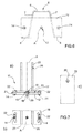
- the regulating system 10 comprises a joint 11 for regulating the inclination of the solar panel 2 set at a top end of the omega pole 5.
- the joint 11 comprises a fixing plate 12, which is welded on the head of the omega pole 5, in particular to the two front-wall flanges 8 and to the two side walls 7.
- the plate 12 further comprises a central through hole 13 having an axis A and two lateral through holes 14 made at respective ends of the fixing plate 12.
- the joint 11 then comprises an adapter 15, which is crescent-shaped and has a length that substantially approximates the width of the fixing plate 12.
- the adapter 15 is set approximately in the middle of the fixing plate 12 and is connected to the fixing plate 12 by means of a connection element 16 coaxial to the axis A.
- the adapter 15 has: a bottom surface that is substantially smooth and plane, which, in use, rests on a top surface 17 of the fixing plate 12; and a top surface 18, which is substantially cylindrical and has an axis V perpendicular to the axis A.
- the joint 8 then comprises a further plate 19, which has dimensions substantially the same as the dimensions of the fixing plate 12.
- the plate 19 has a seat 20, which is made on a bottom surface 20 of the plate 19 and has a shape complementary to the cylindrical top surface 18 of the adapter 15.
- the adapter 15 is set between the two plates designated by 12 and 19, which consequently are at a slight distance apart from one another in such a way that the plate 19 can move and vary its inclination with respect to the plane defined by the top surface 17 of the fixing plate 12.
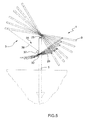
- the plate 19 can tilt and/or rock by approximately 8° with respect to the plane defined by the top surface 17 of the fixing plate 12. According to further variants, it is possible to increase the degree of inclination of the plate 19 intervening on the shape of the adapter 15, which could alternatively have other developments, or else on the height of the adapter 15.
- the plate 19 further comprises two through slots 22, which are the same as one another and a provided at respective ends of the plate 19.
- Each of the two slots 22 faces, in use, a respective lateral through hole 14 of the fixing plate 12, has a profile shaped like the arc of a circumference and is coaxial to the axis A, as illustrated more clearly in Figure 7b .
- the joint 11 then comprises fixing means 23 for connecting the two plates 12 and 19.
- the fixing means 23 comprise a pair of pins 24, each of which slides within a respective lateral through hole 14 and a respective through slot 22 and is provided with two bushings at its respective ends to prevent them from sliding out.
- the plate 19 is free to turn about the axis A so as to vary its inclination.
- each through slot 22 slides with respect to the respective fixed pin 24.
- the extent of the rotation is clearly determined by the extent of the through slots 22 set within which is the respective pin 24.
- the supporting element 3 then comprises two plates 25, which are connected to a top surface of the plate 19 and each have a respective through hole 26 made at a top end.
- the two plates 25 function as support for the rod 9 for supporting the solar panel 2, which is hinged to the two plates 25, approximately in its median point by means of further fixing means 27, which co-operate with the through holes 26.
- the omega pole 5 comprises a through slit 28 made in the rear wall 6, at an intermediate height of its emerging portion.
- the supporting element 3 then comprises a graduated rod 29 for regulating the inclination of the solar panel 2.
- Said graduated rod 28 is connected at a free end in a fixed way to a bottom surface of the supporting rod 9 opposite to the surface in contact with the solar panel 2.
- the graduated rod 29 is then inserted within the through slit 28 of the omega pole 5.
- the omega pole 5 has two rear fixing plates 30, which are welded to the rear wall 6 at opposite sides of the through slit 28 provided in the rear wall 6 itself.
- Each of the two rear plates 30 has a through hole 31, said through holes 31 facing one another.
- the graduated rod 29 comprises a plurality of through holes 32 set at the same distance apart from one another.
- connection of the graduated rod 29 to the omega pole 5 is provided by further fixing means 33.
- the fixing means 33 comprise a pin 34 inserted within the through holes 31 of the two rear plates 30 and within any through hole 32 made on the graduated rod 29, a rear portion of which exiting from the through slit 28 is set between the two rear plates 30.
- the fixing means 33 further comprise a cotter pin, which is designed to prevent the pin 34 from sliding out from said through holes.
- the supporting element 3 then comprises a device 35 for aid to pulling comprising a steel cable 36, which is connected to a top free end of the supporting rod 9 for assisting the operator when he has to vary the inclination of the solar panel 2 and hence of the supporting element 3.
- the steel cable 36 is wound by means of a winch 37 comprising a drum with horizontal axis, the movement of which can be selectively manual (if provided by means of a crank on which the operator acts) or else controlled by actuation means (such as, for example, an electric or hydraulic motor, etc.).
- the central supporting element 3 of the support 1 for solar panels 2 is provided with the device 35 for aid to pulling, whereas the supporting elements 3 arranged at respective ends of the solar panel 2 are without them.
- the fixing plate 12 comprises a central through slit, instead of the central through hole 13.
- the adapter 15 and the corresponding fixing element 26 can translate with respect to the fixing plate 12.
- the stroke of the adapter 15 is determined by the extent of the through slit.
- the omega pole 5 can have selectively further shapes of its cross section, such as for example an H shape, or else a tubular shape.
- the system 10 for regulating the inclination of the solar panel 2 comprises a rack system or any other type of mobile mechanical connection.
- the supporting element 3 does not comprise the device 35 for aid to pulling.
- the supporting element 3 is not provided with the graduated rod 29 and comprises a graduated element having further geometrical developments, such as, for example, a substantially semicircular shape.
- the operator In use, the operator has to bring the solar panel 2 to the desired inclination using the indications provided on the graduated rod 29. Once the desired inclination has been reached, he has to couple the graduated rod 29 to the omega pole 5 inserting the pin 34, and then block the coupling by means of the cotter pin.
- the three supporting elements 3 are tensioned by acting on the device 35 for aid to pulling, i.e., on the winch 37.
- the solar panel 2 can be provided with a plurality of sensors, which send a signal to a control unit.
- the control unit processes the data sent by the sensors by means of a purposely provided astronomic algorithm to supply an estimate of the best possible inclination for the solar panel 2.
- the support 1 described so far presents the advantages of enabling variation of the inclination of the solar panel 2 so as to track the best position with respect to the Sun, and moreover the support 1 can be conveniently moved by just one operator, who can perform all the operations in sequence on his own.
Landscapes
- Engineering & Computer Science (AREA)
- Physics & Mathematics (AREA)
- Life Sciences & Earth Sciences (AREA)
- Sustainable Development (AREA)
- Sustainable Energy (AREA)
- Thermal Sciences (AREA)
- Chemical & Material Sciences (AREA)
- Combustion & Propulsion (AREA)
- Mechanical Engineering (AREA)
- General Engineering & Computer Science (AREA)
- Photovoltaic Devices (AREA)
- Laminated Bodies (AREA)
Applications Claiming Priority (1)
| Application Number | Priority Date | Filing Date | Title |
|---|---|---|---|
| IT000131A ITBO20100131A1 (it) | 2010-03-04 | 2010-03-04 | Supporto per pannelli solari |
Publications (2)
| Publication Number | Publication Date |
|---|---|
| EP2363662A2 true EP2363662A2 (de) | 2011-09-07 |
| EP2363662A3 EP2363662A3 (de) | 2012-06-27 |
Family
ID=43416754
Family Applications (1)
| Application Number | Title | Priority Date | Filing Date |
|---|---|---|---|
| EP11157099A Withdrawn EP2363662A3 (de) | 2010-03-04 | 2011-03-04 | Träger für Sonnenkollektoren |
Country Status (2)
| Country | Link |
|---|---|
| EP (1) | EP2363662A3 (de) |
| IT (1) | ITBO20100131A1 (de) |
Cited By (11)
| Publication number | Priority date | Publication date | Assignee | Title |
|---|---|---|---|---|
| AT512937B1 (de) * | 2012-12-04 | 2013-12-15 | Scheider Josef | Tragvorrichtung für Solarpanele |
| WO2013139745A3 (de) * | 2012-03-19 | 2014-01-30 | Ideematec Deutschland Gmbh | Nachführvorrichtung für solarmodule |
| FR2995071A1 (fr) * | 2012-08-30 | 2014-03-07 | Herve Riveslange | Appareil d'assistance au relevage de panneaux solaires |
| WO2014070124A1 (ru) * | 2012-11-05 | 2014-05-08 | Товарыство З Обмэжэною Видповидальнистю "Токмак Солар Энэрджи" | Одноприводная механическая система с ориентацией панелей солнечных батарей |
| JP2014103334A (ja) * | 2012-11-22 | 2014-06-05 | Hory Corp | ソーラーパネル用架台 |
| KR101485056B1 (ko) | 2013-07-31 | 2015-01-22 | 주식회사 케이디파워 | 태양광 발전장치 |
| CN104932556A (zh) * | 2015-06-10 | 2015-09-23 | 安徽朗坤物联网有限公司 | 利用地下浅层土壤温度跟踪太阳赤纬角的装置及调节方法 |
| JP2016167956A (ja) * | 2015-03-10 | 2016-09-15 | イワブチ株式会社 | ソーラパネル取付架台 |
| FR3073543A1 (fr) * | 2017-11-11 | 2019-05-17 | Nicolas Ferez | Ombriere photovoltaique a nettoyage de panneaux photovoltaiques facilite |
| EP4343226A1 (de) * | 2022-09-23 | 2024-03-27 | Thomas Bockmeyer | Solarpaneel und zaun, ausgestattet mit mindestens einem derartigen solarpaneel |
| US12199551B2 (en) | 2022-04-18 | 2025-01-14 | Sunnoo Inc. | Solar panel turret apparatus |
Citations (10)
| Publication number | Priority date | Publication date | Assignee | Title |
|---|---|---|---|---|
| JPS60122867A (ja) | 1983-12-07 | 1985-07-01 | Eikichi Takigawa | 反射板付コレクタ− |
| DE8520407U1 (de) | 1985-07-15 | 1985-09-26 | Siemens AG, 1000 Berlin und 8000 München | Haltevorrichtung für eine Anzahl von Paneelen, die mit Solarzellen bestückt sind |
| US4995377A (en) | 1990-06-29 | 1991-02-26 | Eiden Glenn E | Dual axis solar collector assembly |
| DE9106505U1 (de) | 1991-05-27 | 1991-07-25 | Wenzel, Joachim, Dipl.-Ing., 7000 Stuttgart | Solarvorrichtung |
| DE102005012054A1 (de) | 2005-03-16 | 2006-09-21 | Oskar Fleck | Halterung für Solarmodule am Dach |
| DE202006014047U1 (de) | 2006-09-13 | 2006-12-07 | Leichtmetallbau Schletter Gmbh | Stellsystem für aufgeständerte Solaranlagen |
| DE202008001010U1 (de) | 2008-01-23 | 2008-05-08 | SGGT Straßenausstattungen GmbH | Tragkonstruktion für Solarmodule |
| DE202008015017U1 (de) | 2008-11-12 | 2009-01-15 | SGGT Straßenausstattungen GmbH | Solarmodul-Tragkonstruktion |
| WO2009013607A2 (fr) | 2007-07-23 | 2009-01-29 | Vergnet Hydro Sas | Générateur photovoltaïque surélevé |
| EP2109152A2 (de) | 2008-04-10 | 2009-10-14 | Leichtmetallbau Schletter GmbH | Montagesystem für Ständer für Photovoltaik-Freiflächenanlagen |
Family Cites Families (6)
| Publication number | Priority date | Publication date | Assignee | Title |
|---|---|---|---|---|
| JPS5792657A (en) * | 1980-11-29 | 1982-06-09 | Masao Nakajima | Sunflower type solar heat absorber |
| DE10162116B4 (de) * | 2001-10-30 | 2004-10-07 | Löschmann, Thomas | Solaranlage |
| JP2005064147A (ja) * | 2003-08-08 | 2005-03-10 | Sumiden Asahi Industries Ltd | ソーラーパネルの架台 |
| KR101003294B1 (ko) * | 2007-02-21 | 2010-12-22 | 주식회사 폴리플러스 | 태양광 집광기구 및 그를 이용한 태양광 집속식 발전장치 |
| DE202007008377U1 (de) * | 2007-06-15 | 2007-08-09 | Krinner Innovation Gmbh | Träger mit Sonnenstandsnachführung für ein Solarmodul |
| DE202009001983U1 (de) * | 2009-03-19 | 2009-05-28 | SCHÜCO International KG | Montagevorrichtung zum Aufstellen von Solarkollektoren, insbesondere Photovoltaikmodulen |
-
2010
- 2010-03-04 IT IT000131A patent/ITBO20100131A1/it unknown
-
2011
- 2011-03-04 EP EP11157099A patent/EP2363662A3/de not_active Withdrawn
Patent Citations (10)
| Publication number | Priority date | Publication date | Assignee | Title |
|---|---|---|---|---|
| JPS60122867A (ja) | 1983-12-07 | 1985-07-01 | Eikichi Takigawa | 反射板付コレクタ− |
| DE8520407U1 (de) | 1985-07-15 | 1985-09-26 | Siemens AG, 1000 Berlin und 8000 München | Haltevorrichtung für eine Anzahl von Paneelen, die mit Solarzellen bestückt sind |
| US4995377A (en) | 1990-06-29 | 1991-02-26 | Eiden Glenn E | Dual axis solar collector assembly |
| DE9106505U1 (de) | 1991-05-27 | 1991-07-25 | Wenzel, Joachim, Dipl.-Ing., 7000 Stuttgart | Solarvorrichtung |
| DE102005012054A1 (de) | 2005-03-16 | 2006-09-21 | Oskar Fleck | Halterung für Solarmodule am Dach |
| DE202006014047U1 (de) | 2006-09-13 | 2006-12-07 | Leichtmetallbau Schletter Gmbh | Stellsystem für aufgeständerte Solaranlagen |
| WO2009013607A2 (fr) | 2007-07-23 | 2009-01-29 | Vergnet Hydro Sas | Générateur photovoltaïque surélevé |
| DE202008001010U1 (de) | 2008-01-23 | 2008-05-08 | SGGT Straßenausstattungen GmbH | Tragkonstruktion für Solarmodule |
| EP2109152A2 (de) | 2008-04-10 | 2009-10-14 | Leichtmetallbau Schletter GmbH | Montagesystem für Ständer für Photovoltaik-Freiflächenanlagen |
| DE202008015017U1 (de) | 2008-11-12 | 2009-01-15 | SGGT Straßenausstattungen GmbH | Solarmodul-Tragkonstruktion |
Cited By (13)
| Publication number | Priority date | Publication date | Assignee | Title |
|---|---|---|---|---|
| WO2013139745A3 (de) * | 2012-03-19 | 2014-01-30 | Ideematec Deutschland Gmbh | Nachführvorrichtung für solarmodule |
| FR2995071A1 (fr) * | 2012-08-30 | 2014-03-07 | Herve Riveslange | Appareil d'assistance au relevage de panneaux solaires |
| WO2014070124A1 (ru) * | 2012-11-05 | 2014-05-08 | Товарыство З Обмэжэною Видповидальнистю "Токмак Солар Энэрджи" | Одноприводная механическая система с ориентацией панелей солнечных батарей |
| JP2014103334A (ja) * | 2012-11-22 | 2014-06-05 | Hory Corp | ソーラーパネル用架台 |
| EP2741027A3 (de) * | 2012-12-04 | 2014-12-24 | Scheider Solutions | Tragvorrichtung für Solarpaneele |
| AT512937A4 (de) * | 2012-12-04 | 2013-12-15 | Scheider | Tragvorrichtung für Solarpanele |
| AT512937B1 (de) * | 2012-12-04 | 2013-12-15 | Scheider Josef | Tragvorrichtung für Solarpanele |
| KR101485056B1 (ko) | 2013-07-31 | 2015-01-22 | 주식회사 케이디파워 | 태양광 발전장치 |
| JP2016167956A (ja) * | 2015-03-10 | 2016-09-15 | イワブチ株式会社 | ソーラパネル取付架台 |
| CN104932556A (zh) * | 2015-06-10 | 2015-09-23 | 安徽朗坤物联网有限公司 | 利用地下浅层土壤温度跟踪太阳赤纬角的装置及调节方法 |
| FR3073543A1 (fr) * | 2017-11-11 | 2019-05-17 | Nicolas Ferez | Ombriere photovoltaique a nettoyage de panneaux photovoltaiques facilite |
| US12199551B2 (en) | 2022-04-18 | 2025-01-14 | Sunnoo Inc. | Solar panel turret apparatus |
| EP4343226A1 (de) * | 2022-09-23 | 2024-03-27 | Thomas Bockmeyer | Solarpaneel und zaun, ausgestattet mit mindestens einem derartigen solarpaneel |
Also Published As
| Publication number | Publication date |
|---|---|
| ITBO20100131A1 (it) | 2011-09-05 |
| EP2363662A3 (de) | 2012-06-27 |
Similar Documents
| Publication | Publication Date | Title |
|---|---|---|
| EP2363662A2 (de) | Träger für Sonnenkollektoren | |
| JP5230025B2 (ja) | ソーラーコレクタアセンブリ用チルトアセンブリ | |
| US20080251115A1 (en) | Solar Panel Array Sun Tracking System | |
| CA2687346A1 (en) | Boom mountable robotic arm | |
| KR101346684B1 (ko) | 태양광 발전용 추적장치 | |
| US20130032135A1 (en) | Apparatuses and Methods for Determining and Changing the Orientation of Solar Energy Capture Devices | |
| WO2012122507A2 (en) | Low cost sun tracking pole mount for solar panels | |
| HUP0203967A2 (en) | Antenna mast and device for adjusting an antenna orientation | |
| KR20200076914A (ko) | 키트화 된 3축형 태양추적 구조물 | |
| CN114429732A (zh) | 曲率调节装置、显示装置及显示装置治具 | |
| CN105468025A (zh) | 光伏双轴联动跟踪系统 | |
| CN213776953U (zh) | 一种具有水平调节功能的工程勘测用支架 | |
| KR101380395B1 (ko) | 태양열 집광패널의 구동시스템 | |
| US20130291926A1 (en) | Solar Tracking Apparatus | |
| CN215925710U (zh) | 一种桥梁施工用安全支撑托架 | |
| CA2493650A1 (en) | Positioning system for portable solar panels | |
| WO2009127758A2 (es) | Estructura para seguidor solar y procedimiento de instalación | |
| JP3153925U (ja) | 太陽電池パネルの架台構造 | |
| EP2792967A2 (de) | Modulares Montagesystem für Paneel | |
| CN219576535U (zh) | 拼接式电缆布线架 | |
| AU2008231263B2 (en) | Tilt assembly for tracking solar collector assembly | |
| CN115355881B (zh) | 基于升降式通信铁塔检测用的倾斜度测量装置 | |
| CN203579038U (zh) | 一种用于虹吸悬吊管焊接的管件助推器 | |
| CN207149918U (zh) | 一种用于配电柜的支架及具有该支架的配电系统 | |
| CN223786124U (zh) | 多画面显示监测报警系统 |
Legal Events
| Date | Code | Title | Description |
|---|---|---|---|
| PUAI | Public reference made under article 153(3) epc to a published international application that has entered the european phase |
Free format text: ORIGINAL CODE: 0009012 |
|
| AK | Designated contracting states |
Kind code of ref document: A2 Designated state(s): AL AT BE BG CH CY CZ DE DK EE ES FI FR GB GR HR HU IE IS IT LI LT LU LV MC MK MT NL NO PL PT RO RS SE SI SK SM TR |
|
| AX | Request for extension of the european patent |
Extension state: BA ME |
|
| PUAL | Search report despatched |
Free format text: ORIGINAL CODE: 0009013 |
|
| AK | Designated contracting states |
Kind code of ref document: A3 Designated state(s): AL AT BE BG CH CY CZ DE DK EE ES FI FR GB GR HR HU IE IS IT LI LT LU LV MC MK MT NL NO PL PT RO RS SE SI SK SM TR |
|
| AX | Request for extension of the european patent |
Extension state: BA ME |
|
| RIC1 | Information provided on ipc code assigned before grant |
Ipc: F24J 2/54 20060101ALI20120522BHEP Ipc: F24J 2/52 20060101AFI20120522BHEP |
|
| STAA | Information on the status of an ep patent application or granted ep patent |
Free format text: STATUS: THE APPLICATION IS DEEMED TO BE WITHDRAWN |
|
| 18D | Application deemed to be withdrawn |
Effective date: 20130103 |