EP2363669A2 - Dispositif d'entretien pour les systèmes de conditionnement - Google Patents
Dispositif d'entretien pour les systèmes de conditionnement Download PDFInfo
- Publication number
- EP2363669A2 EP2363669A2 EP20110154852 EP11154852A EP2363669A2 EP 2363669 A2 EP2363669 A2 EP 2363669A2 EP 20110154852 EP20110154852 EP 20110154852 EP 11154852 A EP11154852 A EP 11154852A EP 2363669 A2 EP2363669 A2 EP 2363669A2
- Authority
- EP
- European Patent Office
- Prior art keywords
- refrigerating fluid
- configuration
- conditioning system
- chamber
- tank
- Prior art date
- Legal status (The legal status is an assumption and is not a legal conclusion. Google has not performed a legal analysis and makes no representation as to the accuracy of the status listed.)
- Withdrawn
Links
Images

Classifications
-
- F—MECHANICAL ENGINEERING; LIGHTING; HEATING; WEAPONS; BLASTING
- F25—REFRIGERATION OR COOLING; COMBINED HEATING AND REFRIGERATION SYSTEMS; HEAT PUMP SYSTEMS; MANUFACTURE OR STORAGE OF ICE; LIQUEFACTION SOLIDIFICATION OF GASES
- F25B—REFRIGERATION MACHINES, PLANTS OR SYSTEMS; COMBINED HEATING AND REFRIGERATION SYSTEMS; HEAT PUMP SYSTEMS
- F25B45/00—Arrangements for charging or discharging refrigerant
-
- B—PERFORMING OPERATIONS; TRANSPORTING
- B60—VEHICLES IN GENERAL
- B60H—ARRANGEMENTS OF HEATING, COOLING, VENTILATING OR OTHER AIR-TREATING DEVICES SPECIALLY ADAPTED FOR PASSENGER OR GOODS SPACES OF VEHICLES
- B60H1/00—Heating, cooling or ventilating devices
- B60H1/00507—Details, e.g. mounting arrangements, desaeration devices
- B60H1/00585—Means for monitoring, testing or servicing the air-conditioning
-
- F—MECHANICAL ENGINEERING; LIGHTING; HEATING; WEAPONS; BLASTING
- F25—REFRIGERATION OR COOLING; COMBINED HEATING AND REFRIGERATION SYSTEMS; HEAT PUMP SYSTEMS; MANUFACTURE OR STORAGE OF ICE; LIQUEFACTION SOLIDIFICATION OF GASES
- F25B—REFRIGERATION MACHINES, PLANTS OR SYSTEMS; COMBINED HEATING AND REFRIGERATION SYSTEMS; HEAT PUMP SYSTEMS
- F25B2345/00—Details for charging or discharging refrigerants; Service stations therefor
- F25B2345/001—Charging refrigerant to a cycle
-
- F—MECHANICAL ENGINEERING; LIGHTING; HEATING; WEAPONS; BLASTING
- F25—REFRIGERATION OR COOLING; COMBINED HEATING AND REFRIGERATION SYSTEMS; HEAT PUMP SYSTEMS; MANUFACTURE OR STORAGE OF ICE; LIQUEFACTION SOLIDIFICATION OF GASES
- F25B—REFRIGERATION MACHINES, PLANTS OR SYSTEMS; COMBINED HEATING AND REFRIGERATION SYSTEMS; HEAT PUMP SYSTEMS
- F25B2345/00—Details for charging or discharging refrigerants; Service stations therefor
- F25B2345/002—Collecting refrigerant from a cycle
-
- F—MECHANICAL ENGINEERING; LIGHTING; HEATING; WEAPONS; BLASTING
- F25—REFRIGERATION OR COOLING; COMBINED HEATING AND REFRIGERATION SYSTEMS; HEAT PUMP SYSTEMS; MANUFACTURE OR STORAGE OF ICE; LIQUEFACTION SOLIDIFICATION OF GASES
- F25B—REFRIGERATION MACHINES, PLANTS OR SYSTEMS; COMBINED HEATING AND REFRIGERATION SYSTEMS; HEAT PUMP SYSTEMS
- F25B2700/00—Sensing or detecting of parameters; Sensors therefor
- F25B2700/04—Refrigerant level
Definitions
- the present invention has as its subject a maintenance device for conditioning systems, in particular for vehicle conditioning systems.
- the present invention finds its principal application in the automobile field, especially in vehicle repair shops.
- This operation is typically performed using dedicated devices for the maintenance of conditioning systems which are capable of recovering, recycling and refilling the refrigerating fluid into the system itself.
- devices of the known art have a recycling unit which removes the refrigerating fluid (typically R134a or similar) from the conditioning system for the purpose of filtering and purifying it.
- refrigerating fluid typically R134a or similar
- the recycling unit comprises an intake valve, an absorption filter which enables the refrigerating fluid to be separated from the exhausted oils, and a condenser.
- This depositing tank is provided with an auxiliary intake through which a user is able to introduce further refrigerating fluid for "topping up".
- a depression is created which moves the refrigerating fluid from the tank towards the conditioning system through a dedicated delivery pipe.
- this delivery pipe In an end portion of this delivery pipe there is typically present an injection joint which is connected to the conditioning system to allow the injection of refrigerating fluid into the system, completing its refilling.
- the majority of the devices of the known art comprises a load cell connected to the tank so as to be capable of measuring its mass for the purpose of monitoring both the quantity of "recycled” refrigerating fluid and the quantity subsequently injected into the conditioning system.
- the load cell is a very delicate element which can easily be damaged as a result of mechanical stresses.
- the technical task at the base of the present invention is to propose a maintenance device for conditioning systems which will overcome the disadvantages of the known art mentioned above.
- no. 1 indicates a maintenance device for conditioning systems in accordance with the present invention.
- Device 1 comprises a recycling unit 2 for a refrigerating fluid removed from a conditioning system, a depositing tank 3 for the refrigerating fluid and a refilling unit 4 capable of injecting the recycled refrigerating fluid, together with the additional "topping up" fluid, into the conditioning system.
- the recycling unit 2 features a recovery unit 5 for the refrigerating fluid and a filtering unit 6 for recycling this refrigerating fluid.
- the recovery unit 5 is connected to the conditioning system by means of a junction 7, preferably sealed, from which the refrigerating fluid to be filtered is drawn.
- the recovery unit 5 comprises a suction organ 8 which generates a depression such as to allow the refrigerating fluid to be drawn off.
- the suction organ 8 comprises a vacuum pump or compressor 9.
- the recycling unit 2 Downstream the recovery unit 5, the recycling unit 2 comprises a filtering unit 6 suitable for purifying the refrigerating fluid from the agents with which it is currently in contact during the refrigerating cycles which it performs in the conditioning system.
- the filtering unit 6 comprises a separation organ 11 capable of separating the refrigerating fluid from the exhausted oils, so as to make it recyclable and reusable inside the conditioning system.
- the separation organ 11 is advantageously formed by a distiller 11a.
- the refrigerating fluid is carried in gaseous form, making the separation from the exhausted oils simple.
- the filtering unit 6 comprises a compressor 12 in order to facilitate the separation between the oils and residues of refrigerating fluid.
- the compressor 12 is equipped with a further separation organ 13 similar to the previous one.
- the filtering unit 6 comprises a drain for the exhausted oils 14.
- the refrigerating fluid is carried in the gaseous state, downstream the filtering unit 6 there is a condenser 15, which returns the majority of the refrigerating fluid to the liquid state so as to allow it to be simply stored.
- the depositing tank 3 for the refrigerating fluid downstream the condenser 15 is located the depositing tank 3 for the refrigerating fluid, in which the purified fluid is stored while awaiting being refilled into the conditioning system.
- This depositing tank 3 is a pressure container which tends to maintain the refrigerating fluid in the liquid state.
- the tank can have a capacity variable between 5 litres and more than 50 litres.
- This tank 3 features a plurality of nozzles for the fluid to enter or leave.
- the tank 3 has at least one first entry nozzle 3a in fluid connection with the condenser 15 and a second entry nozzle 3b from which a user has the possibility of topping up the fluid present in the tank 3 with a further quantity of the same, so as to restore the correct quantity to be injected into the conditioning system.
- Tank 3 features furthermore an exit nozzle 3c in fluid connection with the previously mentioned refilling unit 4.
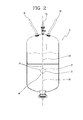
- a level sensor 16 ( figure 2 ) is associated to the tank 3 to measure the level of refrigerating fluid present therein.
- this makes it possible to assess the quantity of purified fluid removed from the conditioning system, so as to be able to carry out measurements and checks on the level of sealing of the conditioning system itself.
- the level sensor 16 in fact, makes it possible to measure the volume of refrigerating fluid recovered and, by the use of further pressure and temperature sensors, it is possible to deduce the value in mass terms of the refrigerating fluid recovered.
- this makes it possible to avoid the use of the load cell for carrying out diagnostic analyses on the sealing of the conditioning system.
- the level sensor 16 is located internally to the tank 3.
- the level sensor 16 comprises a float 17 and a guide 18 located inside the tank 3.
- the guide 18 is oriented perpendicularly to the free surface of the refrigerating fluid in the tank.
- the float 17 is slidably attached to the guide 18 to determine the fluid level with extreme precision.
- the level sensor 16 comprises a magnetostrictive sensor connected to the float 17 and/or the guide 18.
- a magnet 19 is anchored to the float 17 and is slidable along the guide 18, to which is anchored a magnetostrictive wire 20.
- magnetostrictive sensors allow highly accurate measurements, making very limited top-ups of the conditioning system possible.
- the refilling unit 4 draws the refrigerating fluid from the tank 3 and injects it into the conditioning system to refill it.
- this refilling unit 4 sucks the refrigerating fluid from the tank 3, compresses this fluid and finally injects it into the conditioning system.
- the refilling unit 4 comprises a volumetric dosing device 22 featuring a chamber 23 switchable from a minimum volume configuration to a maximum volume configuration for sucking into the chamber 23 a quantity of refrigerating fluid substantially equal to the maximum volume 23.
- the chamber 23 is of variable volume between a maximum value and a minimum value so as to accept within it a quantity of refrigerating fluid substantially equal to the maximum value of the chamber 23.
- the chamber 23 is switchable from the maximum to the minimum volume configuration in order to compress the sucked refrigerating fluid before injecting said refrigerating fluid into the conditioning system. More precisely, the chamber 23 has at least one movable wall 23a to reduce its volume and/or compress the sucked refrigerating fluid, at a stage immediately previous to the injection of the refrigerating fluid into the conditioning system.
- the volumetric dosing device 22 comprises a cylinder 22a and a piston 22b slidable in the cylinder 22a so as to form the variable-volume chamber 23.
- an active portion of the piston 22b forms the movable wall 23a.
- the piston 22b slides in one direction to expand the volume of the chamber 23 and take the chamber 23 from the minimum volume configuration to the maximum volume configuration, sucking the refrigerating fluid from the tank 3.
- the chamber 23 also slides in the opposite direction to reduce the volume of the chamber 23 and bring the chamber 23 from the maximum volume configuration to the minimum volume configuration, injecting the refrigerating fluid contained therein into the conditioning system.
- the maximum volume of the chamber 23 being known, or rather the stroke of the piston 22b being known, it is simple to calculate the volume of refrigerating fluid drawn in from the tank 3, and, consequently, knowing injection pressure and temperature, to know the quantity injected in mass terms.
- the cylinder 22a is of pneumatic type.
- the piston 22b is moved by compressed air injected through electrovalves 24, suitably controlled.
- the movement can occur through hydraulic or electrical actuation.
- the refilling unit 4 comprises a valve 25 to regulate the flow of the refrigerating fluid, located operationally downstream of the volumetric dosing device 22.
- valve 25 is located downstream of the cylinder 22a.
- This valve 25 is controllable and switchable between a locking configuration, in which it impedes the passage of the refrigerating fluid, and a discharge configuration, in which it allows the passage of the refrigerating fluid.
- the valve 25 is in locking configuration when the chamber 23 passes from the maximum volume configuration to an intermediate configuration in order to allow the refrigerating fluid to be compressed.
- the valve 25 passes from the locking configuration to the discharge configuration.
- the piston 22b is actuated in order to reduce the volume of chamber 23.
- this compression allows all the refrigerating fluid to be brought to the liquid phase, i.e. ready to be reintroduced into the conditioning system.
- valve 25 is brought into discharge configuration to allow the injection of the refrigerating fluid into the conditioning system.
- the device in proximity to the valve 25 there is located a union connecting with the conditioning system.
- the device comprises flow-regulating means 26 for regulating the flow of refrigerating fluid to enable this refrigerating fluid to flow only along a preset advancing direction "A". More precisely, the regulating means 26 comprise at least one pair of retaining valves 27 placed respectively immediately upstream and immediately downstream of the volumetric dosing device 22.
- a first retaining valve 27a is located in proximity to an entrance to the chamber 23 so as to allow the refrigerating fluid to flow only inwards.
- a second retaining valve 27b is located in proximity to an exit from the chamber 23 so as to allow the refrigerating fluid to flow only outwards from the chamber 23 itself.
- this prevents backflow of the refrigerating fluid towards the tank 3 once the fluid itself has entered the chamber 23.
- the device according to the present invention comprises a processing unit (not illustrated) which relates together the parameters for level, temperature and pressure of the fluid so as to deduce the mass of refrigerating fluid inside the tank 3.
- a processing unit not illustrated
- the parameters for level, temperature and pressure of the fluid so as to deduce the mass of refrigerating fluid inside the tank 3.
- the processing unit is also capable of relating, with known formulae, the stroke of the piston 22b with the temperature and injection pressure to deduce the mass of refrigerating fluid injected during refilling.
- the processing unit is suitable for receiving a first signal representing the volume of refrigerating fluid injected, and comprises a sub-unit suitable for processing this first signal and sending a second signal representing the mass of injected refrigerating fluid.
- the invention achieves the proposed objects and obtains important advantages.
- volumetric dosing device having the chamber of variable volume, but known, renders more reliable and functional the procedure for refilling the conditioning system.
- a quantity of refrigerating fluid equal to the maximum volume of the chamber is drawn from the tank and subsequently injected into the system, without the need for measurements of mass to check the quantity of fluid used, thus eliminating the load cell, which is a component of low reliability and difficult to calibrate.
- the stage of compressing the fluid immediately after sucking it into the chamber guarantees that all the refrigerating fluid injected into the conditioning system is completely in the liquid state.
- the presence of a level sensor eliminates the need to use a load cell for the purpose of measuring the quantity of refrigerating fluid removed from the systems at the recovery stage.
- the senor being magnetostrictive ensures a far higher degree of accuracy than is ensured by the load cell, and this allows the conditioning system to be topped up even with small quantities without incurring error.
Landscapes
- Engineering & Computer Science (AREA)
- Physics & Mathematics (AREA)
- Thermal Sciences (AREA)
- Mechanical Engineering (AREA)
- General Engineering & Computer Science (AREA)
- Sorption Type Refrigeration Machines (AREA)
- Central Air Conditioning (AREA)
- Loading And Unloading Of Fuel Tanks Or Ships (AREA)
Applications Claiming Priority (1)
| Application Number | Priority Date | Filing Date | Title |
|---|---|---|---|
| ITPR2010A000015A IT1398766B1 (it) | 2010-03-03 | 2010-03-03 | Dispositivo di manutenzione per impianti di condizionamento. |
Publications (1)
| Publication Number | Publication Date |
|---|---|
| EP2363669A2 true EP2363669A2 (fr) | 2011-09-07 |
Family
ID=42799846
Family Applications (1)
| Application Number | Title | Priority Date | Filing Date |
|---|---|---|---|
| EP20110154852 Withdrawn EP2363669A2 (fr) | 2010-03-03 | 2011-02-17 | Dispositif d'entretien pour les systèmes de conditionnement |
Country Status (2)
| Country | Link |
|---|---|
| EP (1) | EP2363669A2 (fr) |
| IT (1) | IT1398766B1 (fr) |
Cited By (4)
| Publication number | Priority date | Publication date | Assignee | Title |
|---|---|---|---|---|
| EP3121039A1 (fr) * | 2015-07-24 | 2017-01-25 | Brain Bee Holding S.p.A. | Procédé permettant de transférer le liquide de refroidissement provenant d'une unité de chargement pour un système de conditionnement d'air |
| DE102016005319A1 (de) * | 2016-05-02 | 2017-11-02 | Inka-Systems Gmbh & Co. Kg | Vorrichtung zum Befüllen eines Tanks eines Kraftfahrzeuges mit einem flüssigen oder gasförmigen Betriebsmittel, insbesondere zur industriellen Erstbefüllung am Montageband des Herstellers |
| CN107843034A (zh) * | 2017-03-28 | 2018-03-27 | 蒋书印 | 无损抽真空汽车空调清洗机 |
| US10054345B2 (en) | 2015-07-28 | 2018-08-21 | Mahle Aftermarket Italy S.P.A. | Method for transferring coolant from a loading unit to an air conditioning system |
Citations (2)
| Publication number | Priority date | Publication date | Assignee | Title |
|---|---|---|---|---|
| JPH08303911A (ja) | 1995-05-12 | 1996-11-22 | Touou Kogyo Kk | 冷媒充填装置 |
| US5722247A (en) | 1996-10-11 | 1998-03-03 | Redi-Controls Inc. | Recovery system for very high-pressure refrigerants |
Family Cites Families (1)
| Publication number | Priority date | Publication date | Assignee | Title |
|---|---|---|---|---|
| US7086237B2 (en) * | 2004-05-06 | 2006-08-08 | Yakov Arshansky | Method and apparatus to measure and transfer liquefied refrigerant in a refrigeration system |
-
2010
- 2010-03-03 IT ITPR2010A000015A patent/IT1398766B1/it active
-
2011
- 2011-02-17 EP EP20110154852 patent/EP2363669A2/fr not_active Withdrawn
Patent Citations (2)
| Publication number | Priority date | Publication date | Assignee | Title |
|---|---|---|---|---|
| JPH08303911A (ja) | 1995-05-12 | 1996-11-22 | Touou Kogyo Kk | 冷媒充填装置 |
| US5722247A (en) | 1996-10-11 | 1998-03-03 | Redi-Controls Inc. | Recovery system for very high-pressure refrigerants |
Cited By (4)
| Publication number | Priority date | Publication date | Assignee | Title |
|---|---|---|---|---|
| EP3121039A1 (fr) * | 2015-07-24 | 2017-01-25 | Brain Bee Holding S.p.A. | Procédé permettant de transférer le liquide de refroidissement provenant d'une unité de chargement pour un système de conditionnement d'air |
| US10054345B2 (en) | 2015-07-28 | 2018-08-21 | Mahle Aftermarket Italy S.P.A. | Method for transferring coolant from a loading unit to an air conditioning system |
| DE102016005319A1 (de) * | 2016-05-02 | 2017-11-02 | Inka-Systems Gmbh & Co. Kg | Vorrichtung zum Befüllen eines Tanks eines Kraftfahrzeuges mit einem flüssigen oder gasförmigen Betriebsmittel, insbesondere zur industriellen Erstbefüllung am Montageband des Herstellers |
| CN107843034A (zh) * | 2017-03-28 | 2018-03-27 | 蒋书印 | 无损抽真空汽车空调清洗机 |
Also Published As
| Publication number | Publication date |
|---|---|
| IT1398766B1 (it) | 2013-03-18 |
| ITPR20100015A1 (it) | 2010-06-02 |
Similar Documents
| Publication | Publication Date | Title |
|---|---|---|
| US12140127B2 (en) | Pump having a pressure sensor to displace a known volume of fluid from a reservoir, which stretches and contracts | |
| EP2363669A2 (fr) | Dispositif d'entretien pour les systèmes de conditionnement | |
| US20160108906A1 (en) | Arrangement and method for measuring a delivery volume and a delivery rate of an intermittently operating pump | |
| CN103890478B (zh) | 从压力气体系统中自动排出冷凝液的改进型方法 | |
| WO2004072586A2 (fr) | Mesure de volumes de fluide dans un recipient par pression | |
| CN103703251A (zh) | 用于计量流体的能够自动排气的隔膜泵和相应方法 | |
| JP6794427B2 (ja) | 管理式比例定量装置及び定量ポンプの管理方法 | |
| JP2003329506A (ja) | 容器内液体の液位測定方法 | |
| JP6223041B2 (ja) | 液体計量装置及び水質分析装置 | |
| US20070177986A1 (en) | Method and apparatus for evaluating a dosing operation | |
| US20070272025A1 (en) | Fuel tank module control system | |
| TWI617362B (zh) | 抽汲系統、用以在一抽汲系統中偵測空氣之方法及電腦程式產品 | |
| US20220236127A1 (en) | Pressure sensing device and blood purification apparatus using same | |
| HK1256982A1 (en) | Supervised proportional metering device and methods for monitoring a metering pump | |
| EP2199710B1 (fr) | Réservoir | |
| CN106872154B (zh) | 一种微启式安全阀排量测试系统以及测试方法 | |
| CN105865728A (zh) | 小流量泄漏的检测方法及装置 | |
| US9823001B2 (en) | Method and system for measuring volume of fluid drained from an air conditioning service unit | |
| CN102713292A (zh) | 借助活塞泵监督取样的装置 | |
| US12330177B2 (en) | Dosing device and method of dosing liquid media | |
| CN209507543U (zh) | 灌装抽吸装置 | |
| CN109607453A (zh) | 灌装抽吸装置及灌装抽吸方法 | |
| CN221577816U (zh) | 一种积液取样装置 | |
| CN114002386B (zh) | 一种用于气体分析系统气源的微型排水装置 | |
| CN208420098U (zh) | 一种环氧乙烷计量罐 |
Legal Events
| Date | Code | Title | Description |
|---|---|---|---|
| PUAI | Public reference made under article 153(3) epc to a published international application that has entered the european phase |
Free format text: ORIGINAL CODE: 0009012 |
|
| AK | Designated contracting states |
Kind code of ref document: A2 Designated state(s): AL AT BE BG CH CY CZ DE DK EE ES FI FR GB GR HR HU IE IS IT LI LT LU LV MC MK MT NL NO PL PT RO RS SE SI SK SM TR |
|
| AX | Request for extension of the european patent |
Extension state: BA ME |
|
| 17P | Request for examination filed |
Effective date: 20111026 |
|
| STAA | Information on the status of an ep patent application or granted ep patent |
Free format text: STATUS: THE APPLICATION IS DEEMED TO BE WITHDRAWN |
|
| 18D | Application deemed to be withdrawn |
Effective date: 20130903 |