EP2363675A2 - Double pipe and heat exchanger having the same - Google Patents
Double pipe and heat exchanger having the same Download PDFInfo
- Publication number
- EP2363675A2 EP2363675A2 EP20110150834 EP11150834A EP2363675A2 EP 2363675 A2 EP2363675 A2 EP 2363675A2 EP 20110150834 EP20110150834 EP 20110150834 EP 11150834 A EP11150834 A EP 11150834A EP 2363675 A2 EP2363675 A2 EP 2363675A2
- Authority
- EP
- European Patent Office
- Prior art keywords
- pipe
- double
- double pipe
- inner pipe
- connector
- Prior art date
- Legal status (The legal status is an assumption and is not a legal conclusion. Google has not performed a legal analysis and makes no representation as to the accuracy of the status listed.)
- Withdrawn
Links
- 230000004888 barrier function Effects 0.000 claims abstract description 22
- 239000003507 refrigerant Substances 0.000 description 43
- 239000007788 liquid Substances 0.000 description 9
- 238000001816 cooling Methods 0.000 description 7
- 238000003780 insertion Methods 0.000 description 6
- 230000037431 insertion Effects 0.000 description 6
- 230000008878 coupling Effects 0.000 description 5
- 238000010168 coupling process Methods 0.000 description 5
- 238000005859 coupling reaction Methods 0.000 description 5
- 238000003466 welding Methods 0.000 description 5
- XEEYBQQBJWHFJM-UHFFFAOYSA-N Iron Chemical compound [Fe] XEEYBQQBJWHFJM-UHFFFAOYSA-N 0.000 description 4
- 239000007789 gas Substances 0.000 description 4
- 230000035515 penetration Effects 0.000 description 4
- 238000004378 air conditioning Methods 0.000 description 3
- 239000002904 solvent Substances 0.000 description 3
- XAGFODPZIPBFFR-UHFFFAOYSA-N aluminium Chemical compound [Al] XAGFODPZIPBFFR-UHFFFAOYSA-N 0.000 description 2
- 229910052782 aluminium Inorganic materials 0.000 description 2
- 238000001704 evaporation Methods 0.000 description 2
- -1 hydro fluoro olefin Chemical group 0.000 description 2
- 229910052742 iron Inorganic materials 0.000 description 2
- 239000000463 material Substances 0.000 description 2
- JRZJOMJEPLMPRA-UHFFFAOYSA-N olefin Natural products CCCCCCCC=C JRZJOMJEPLMPRA-UHFFFAOYSA-N 0.000 description 2
- 239000004033 plastic Substances 0.000 description 2
- 229910001220 stainless steel Inorganic materials 0.000 description 2
- 239000010935 stainless steel Substances 0.000 description 2
- 238000010792 warming Methods 0.000 description 2
- LVGUZGTVOIAKKC-UHFFFAOYSA-N 1,1,1,2-tetrafluoroethane Chemical compound FCC(F)(F)F LVGUZGTVOIAKKC-UHFFFAOYSA-N 0.000 description 1
- 230000008859 change Effects 0.000 description 1
- 238000006243 chemical reaction Methods 0.000 description 1
- 230000006835 compression Effects 0.000 description 1
- 238000007906 compression Methods 0.000 description 1
- 230000006866 deterioration Effects 0.000 description 1
- 230000008020 evaporation Effects 0.000 description 1
- NBVXSUQYWXRMNV-UHFFFAOYSA-N fluoromethane Chemical compound FC NBVXSUQYWXRMNV-UHFFFAOYSA-N 0.000 description 1
- 238000007710 freezing Methods 0.000 description 1
- 230000008014 freezing Effects 0.000 description 1
- ZZUFCTLCJUWOSV-UHFFFAOYSA-N furosemide Chemical compound C1=C(Cl)C(S(=O)(=O)N)=CC(C(O)=O)=C1NCC1=CC=CO1 ZZUFCTLCJUWOSV-UHFFFAOYSA-N 0.000 description 1
- 239000005431 greenhouse gas Substances 0.000 description 1
- 238000000034 method Methods 0.000 description 1
- 238000012986 modification Methods 0.000 description 1
- 230000004048 modification Effects 0.000 description 1
- 230000008569 process Effects 0.000 description 1
Images


Classifications
-
- F—MECHANICAL ENGINEERING; LIGHTING; HEATING; WEAPONS; BLASTING
- F28—HEAT EXCHANGE IN GENERAL
- F28D—HEAT-EXCHANGE APPARATUS, NOT PROVIDED FOR IN ANOTHER SUBCLASS, IN WHICH THE HEAT-EXCHANGE MEDIA DO NOT COME INTO DIRECT CONTACT
- F28D7/00—Heat-exchange apparatus having stationary tubular conduit assemblies for both heat-exchange media, the media being in contact with different sides of a conduit wall
- F28D7/10—Heat-exchange apparatus having stationary tubular conduit assemblies for both heat-exchange media, the media being in contact with different sides of a conduit wall the conduits being arranged one within the other, e.g. concentrically
- F28D7/106—Heat-exchange apparatus having stationary tubular conduit assemblies for both heat-exchange media, the media being in contact with different sides of a conduit wall the conduits being arranged one within the other, e.g. concentrically consisting of two coaxial conduits or modules of two coaxial conduits
-
- F—MECHANICAL ENGINEERING; LIGHTING; HEATING; WEAPONS; BLASTING
- F28—HEAT EXCHANGE IN GENERAL
- F28F—DETAILS OF HEAT-EXCHANGE AND HEAT-TRANSFER APPARATUS, OF GENERAL APPLICATION
- F28F1/00—Tubular elements; Assemblies of tubular elements
- F28F1/10—Tubular elements and assemblies thereof with means for increasing heat-transfer area, e.g. with fins, with projections, with recesses
- F28F1/40—Tubular elements and assemblies thereof with means for increasing heat-transfer area, e.g. with fins, with projections, with recesses the means being only inside the tubular element
-
- F—MECHANICAL ENGINEERING; LIGHTING; HEATING; WEAPONS; BLASTING
- F28—HEAT EXCHANGE IN GENERAL
- F28F—DETAILS OF HEAT-EXCHANGE AND HEAT-TRANSFER APPARATUS, OF GENERAL APPLICATION
- F28F1/00—Tubular elements; Assemblies of tubular elements
- F28F1/10—Tubular elements and assemblies thereof with means for increasing heat-transfer area, e.g. with fins, with projections, with recesses
- F28F1/42—Tubular elements and assemblies thereof with means for increasing heat-transfer area, e.g. with fins, with projections, with recesses the means being both outside and inside the tubular element
-
- F—MECHANICAL ENGINEERING; LIGHTING; HEATING; WEAPONS; BLASTING
- F28—HEAT EXCHANGE IN GENERAL
- F28F—DETAILS OF HEAT-EXCHANGE AND HEAT-TRANSFER APPARATUS, OF GENERAL APPLICATION
- F28F9/00—Casings; Header boxes; Auxiliary supports for elements; Auxiliary members within casings
- F28F9/02—Header boxes; End plates
-
- F—MECHANICAL ENGINEERING; LIGHTING; HEATING; WEAPONS; BLASTING
- F16—ENGINEERING ELEMENTS AND UNITS; GENERAL MEASURES FOR PRODUCING AND MAINTAINING EFFECTIVE FUNCTIONING OF MACHINES OR INSTALLATIONS; THERMAL INSULATION IN GENERAL
- F16L—PIPES; JOINTS OR FITTINGS FOR PIPES; SUPPORTS FOR PIPES, CABLES OR PROTECTIVE TUBING; MEANS FOR THERMAL INSULATION IN GENERAL
- F16L9/00—Rigid pipes
- F16L9/18—Double-walled pipes; Multi-channel pipes or pipe assemblies
Definitions
- the present invention relates to a double pipe and a heat exchanger having the same, and more particularly, to a double pipe and a heat exchanger having the same that can improve heat exchange efficiency of a heat exchanger by providing a double pipe structure having an excellent thermal conductivity performance.
- a vehicle air conditioner is installed in a vehicle to send a cold air into a vehicle room, thereby cooling the vehicle.
- a general air conditioning system of such an air conditioner has a freezing cycle formed by connecting, to a refrigerant pipe, a compressor for compressing and sending a refrigerant, a condenser for condensing a high pressure of refrigerant sent from the compressor, an expansion valve for depressurizing a refrigerant condensed and liquefied in the condenser, and an evaporator for cooling air ejected into a vehicle room with an endothermic reaction by an evaporation latent heat of a refrigerant by exchanging a heat of a low pressure of liquid refrigerant depressurized by the expansion valve with a heat of air to be sent into the vehicle room and by evaporating the refrigerant, and cools the vehicle room through a refrigerant circulation process.
- an apparatus that can supercool a liquid refrigerant of a high temperature and a high pressure expanded by an expansion valve and that can appropriately adjust a superheat degree of a refrigerant discharged in an evaporator is necessary, and therefore a recently developing cooling system has a predetermined internal heat exchanger in an expansion valve inhalation side and a compressor inhalation side.
- Such an internal heat exchanger has a double pipe structure and includes an inner pipe connected between a compression pipe in an evaporator and an outer pipe connected between a condenser and an expansion valve.
- Agas refrigerant of a low temperature and a low pressure flows in the inner pipe, and a liquid refrigerant of a high temperature and a high pressure flows in the outer pipe, and they flow in an opposite direction to exchange a heat thereof. That is, a temperature is appropriately adjusted by exchanging a heat of a liquid refrigerant of a high temperature and a high pressure injected into an expansion valve and a heat of a gas refrigerant of a low temperature and a low pressure discharged from an evaporator.
- a hydro fluoro carbon (HFC)-based 134a (R134a) refrigerant which is a presently used global warming material will be replaced with a hydro fluoro olefin (HFO)-based 1234yf refrigerant, which is a low global warming material, and the 1234yf refrigerant to be a replacement in the future has a performance about 15% lower than R134a, which is a present refrigerant in an existing heat exchanger.
- HFC hydro fluoro carbon
- R134a hydro fluoro olefin
- elements constituting an air conditioner such as a compressor, an evaporator, and a condenser should be improved, however in order to improve the elements, much cost is required.
- the present invention has been made in view of the above problems, and provides a double pipe and a heat exchanger having the same that can improve cooling efficiency of a cooling system by improving heat exchange efficiency of a heat exchanger by a double pipe structure.
- a double pipe including an outer pipe and an inner pipe formed within the outer pipe includes: a plurality of barrier ribs formed in a length direction and disposed at a predetermined distance in a circumferential direction between the outer pipe and the inner pipe; and a plurality of protruding portions formed at positions corresponding to each of the plurality of barrier ribs and protruded in a center direction and formed in a length direction of the inner pipe from an inner circumferential surface of the inner pipe.
- a double pipe heat exchanger includes: a double pipe including a plurality of barrier ribs formed in a length direction and disposed at a predetermined distance in a circumferential direction between an outer pipe and an inner pipe, and a plurality of protruding portions formed at positions corresponding to each of the plurality of barrier ribs and protruded in a center direction and formed in a length direction of the inner pipe from an inner circumferential surface of the inner pipe; and a connector coupled to an end portion of the double pipe, wherein all the outer pipe, the inner pipe, the plurality of barrier ribs, and the plurality of protruding portions are integrally formed, and an outer pipe opening for inserting the double pipe is formed at one side of the connector, an inner pipe opening for inserting the other pipe having the same diameter as that of the inner pipe of the double pipe is formed at the other side of the connector, and space to be connected to an outer pipe flow path formed between the inner pipe and the outer pipe of the double pipe is formed within
- FIG. 1 is a perspective view illustrating an integral double pipe of a double pipe heat exchanger according to an exemplary embodiment of the present invention
- FIGS. 2A to 2D are perspective views illustratingmodifiedexamples of the integral double pipe of FIG. 1 .
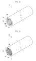
- an integral double pipe 10 according to the present exemplary embodiment includes an outer pipe 11 and an inner pipe 13.
- the integral double pipe 10 includes a plurality of barrier ribs 11a formed in a length direction and disposed at a predetermined distance in a circumferential direction between the outer pipe 11 and the inner pipe 13, and a plurality of protruding portions 13a formed at a position corresponding to each of the plurality of barrier ribs 11a and protruded in a center direction and formed in a length direction of an inner pipe from an inner circumferential surface of the inner pipe 13.
- the outer pipe 11, the plurality of barrier ribs 11a, the inner pipe 13, and the plurality of protruding portions 13a are integrally formed.
- Agas refrigerant of a low temperature and a low pressure flows in the inner pipe 13
- a liquid refrigerant of a high temperature and a high pressure flows in the outer pipe 11
- the refrigerants flow in an opposite direction to exchange a heat thereof.
- a liquid refrigerant of a high temperature and a high pressure flows in an outer pipe flow path 2 formed between the outer pipe 11 and the inner pipe 13.
- Agas refrigerant of a low temperature and a low pressure flows in an inner pipe flow path 3 formed in the inner pipe 13.
- Both the outer pipe 11 and the inner pipe 13 of the integral double pipe 10 have a circular sectional shape, however a shape of the outer pipe 11 and the inner pipe 13 of the integral double pipe 10 is not limited thereto and the outer pipe 11 and the inner pipe 13 can have various polygonal shapes such as a quadrangle, oval, and triangle.
- the barrier rib 11a and the protruding portion 13a have a rectangular sectional shape, but a shape of the barrier rib 11a and the protruding portion 13a is not limited thereto and the barrier rib 11a and the protruding portion 13a can have a polygonal shape such as a circle, oval, and triangle.
- an inner diameter of the outer pipe 11 is 22 mm and a thickness thereof is about 3 mm
- an inner diameter of the inner pipe 13 is 17 mm and a thickness thereof is about 2.4 mm .
- a sectional thickness and height of the barrier rib 11a and the protruding portion 13a are about 1 mm.
- a cylindrical angle formed between the barrier rib 11a and the protruding portion 13a and a next barrier rib 11a and a next protruding portion 13a is about 10 to 30°.
- FIGS. 2A to 2D illustrate modified examples of the integral double pipe 10 of FIG. 1 .
- a plurality of grooves 11b are formed in a length direction at a predetermined distance in a circumferential direction of an outer circumferential surface of the outer pipe 11.
- additional protruding portion 13b is formed between two adjacent protruding portions 13a of a plurality of protruding portions 13a of the inner pipe 13.
- an uneven portion 13c is formed in a portion in which the plurality of protruding portions 13a are not formed.
- the uneven portion 13c is formed in both an outer circumferential surface and an inner circumferential surface of the inner pipe 13, however may be formed only in an outer circumferential surface or an inner circumferential surface of the inner pipe 13. Further, instead of additional protruding portion 13b of FIG. 2B , an uneven portion 13c may be formed.
- an uneven portion 13d is formed in a surface of the protruding portion 13a of the inner pipe 13.
- the uneven portion 13d is formed in the protruding portion 13a of the inner pipe 13, however the uneven portion 13d may be formed in the additional protruding portion 13b of the inner pipe 13 of FIG. 2B .
- the uneven portion 13d may be formed in a plurality of barrier ribs 11a formed between the outer pipe 11 and the inner pipe 13.
- a refrigerant flowing to the integral double pipe 10 may be hydro fluoro olefin (HFO)-based 1234yf.
- a sectional area is formed by a plurality of protruding portions 13a and a plurality of barrier ribs 11a and thus thermal efficiency can be maximized, and thicknesses of the outer pipe and the inner pipe can be minimized.
- the integral double pipe 10 is made of one of aluminum, iron, plastic, and stainless steel.
- FIG. 3A is a perspective view illustrating a connector of the double pipe heat exchanger of FIG. 1
- FIG. 3B is a perspective view illustrating a modified example of the connector of FIG. 3A
- FIG. 4A is a perspective view illustrating an integral double pipe coupled to the connector of FIG. 3A
- FIG. 4B is a perspective view illustrating an integral double pipe coupled to the connector of FIG. 3B .
- a double pipe heat exchanger according to the present exemplary embodiment includes an integral double pipe 10 and a connector 20 coupled to an end portion of the integral double pipe 10.
- an outer pipe opening 23a for inserting the integral double pipe 10 is formed and at the other side thereof, an inner pipe opening 25a for inserting another pipe (13) having the same a diameter as that of the inner pipe 13 of the integral double pipe 10 is formed, and in an inner part thereof, a space 22 to be connected to a flow path between the inner pipe 13 and the outer pipe 11 of the integral double pipe 10 is formed.
- the connector 20 is described in detail hereinafter.
- the inside of the connector 20 is hollow, and the connector 20 includes an outer pipe coupler 23 formed at one end of the connector 20 and having an outer pipe opening 23a for inserting and coupling the outer pipe 11, an inner pipe coupler 25 formed at the other end of the connector 20 and having an inner pipe opening 25a for inserting the inner pipe 13 and for coupling it to an outer circumference of the inner pipe 13, and an external penetration hole 27 for inserting an outer circumferential surface between the outer pipe coupler 23 and the inner pipe coupler 25.
- the inner pipe 13 integrally formed with the outer pipe 11 and another inner pipe 13 inserted through the inner pipe opening 25a from the outside are coupled by welding within the connector 20.
- the inside of the connector 200 in which the connector 20 of FIGS. 3A and 4A is modified is hollow, and the connector 200 includes an outer pipe coupler 203 formed at one end of the connector 20 and having an outer pipe opening 203a for inserting and coupling the outer pipe 11, an inner pipe coupler 205 formed at the other end of the connector 200 and having an inner pipe opening 205a for inserting the inner pipe 13 and for coupling it to the outer circumference of the inner pipe 13, and an external penetration hole 207 for inserting an outer circumferential surface between the outer pipe coupler 203 and the inner pipe coupler 205.
- a difference between the connector 20 of FIG. 3A and the connector 200 of FIG. 3B is that the connector 20 of FIG. 3A has a reduced outer circumferential diameter as advancing to the inner pipe coupler 25, whereas the connector 200 of FIG. 3B has the same outer circumferential diameter in the inner pipe coupler 205 and the outer pipe coupler 203.
- spaces 22 and 202 to be connected to the outer pipe flow path 2 (see FIG. 1 ) of the integral double pipe 10 and the external penetration holes 27 and 207 are formed at the inside between the outer pipe couplers 23 and 203 and the inner pipe couplers 25 and 205 of the connectors 20 and 200, respectively. Therefore, the external insertion holes 27 and 207 and the outer pipe flow path 2 are connected through the spaces 22 and 202, respectively.
- latch jaws 29 and 209 are formed at the inside of the outer pipe couplers 23 and 203, respectively.
- the connectors 20 and 200 are coupled to the outer pipe 111 through outer pipe openings 23a and 203a of outer pipe couplers 23 and 203, and are coupled to the inner pipe 113 through inner pipe openings 25a and 205a such that the inner pipe 113 extends to the outside of the connectors 20 and 200 through inner pipe openings 25a and 205a.
- the outer pipe 11 and the inner pipe 13 are coupled, by welding both ends of each of the connectors 20 and 200, they are fixed and leakage of a solvent is prevented.
- Each of the connectors 20 and 200 is coupled to the other side of the integral double pipe 10, and an outer refrigerant pipe 30 is coupled to each of the external penetration holes 27 and 207 of each of the connectors 20 and 200 coupled to both sides of the integral double pipe 10.
- the outer refrigerant pipe 30 is coupled by welding.
- a closed loop is formed in the outer pipe 11 by each of the connectors 20 and 200 coupled to one side of the integral double pipe 10 and each of the connectors 20 and 200 coupled to the other side thereof, and a liquid refrigerant of a high temperature and a high pressure flows in the outer pipe flow path 2 via each of spaces 22 and 202 through the outer refrigerant pipe 30 coupled to each of the external insertion holes 27 and 207.
- a gas refrigerant of a low temperature and a low pressure flows in an opposite direction and thus heat exchange can be performed.
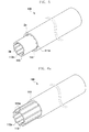
- FIG. 5 is a perspective view illustrating a separated double pipe of a double pipe heat exchanger according to another exemplary embodiment of the present invention
- FIGS. 6A and 6B are perspective views illustrating modified examples of the separated double pipe of FIG. 5 .
- an outer pipe 111 and an inner pipe 113 are separated.
- the separated double pipe 100 includes a plurality of first protruding portions 111a and a plurality of second protruding portions 113a.
- the plurality of first protruding portions 111a are disposed between the outer pipe 111 and the inner pipe 113, formed in a length direction and disposed at a predetermined distance in a circumferential direction in one of an inner circumferential surface of the inner pipe 113 and an outer circumferential surface of the inner pipe 113.
- the plurality of second protruding portions 113a are formed at positions corresponding to each of the plurality of first protruding portions 111a and protruded in a center direction and formed in a length direction of the inner pipe 113 from an inner circumferential surface of the inner pipe 113.
- a liquid refrigerant of a high temperature and a high pressure flows in an outer pipe flow path 2a formed between the outer pipe 111 and the inner pipe 113.
- a gas refrigerant of a low temperature and a low pressure flows an inner pipe flow path 3a formed in the inner pipe 113.
- FIGS. 6A and 6B illustrate modified examples of the separated double pipe 100 of FIG. 5 .
- a first protruding portion 111a formed in an inner circumferential surface of the outer pipe 111 of FIG. 5 is formed in an outer circumferential surface of the inner pipe 113.
- the first protruding portion 111a and the second protruding portions 113a are alternately disposed.
- an uneven portion 113b is formed in a portion in which the second protruding portion 113a is not formed, as shown in FIG. 2C .
- the uneven portion 113b is formed in both an outer circumferential surface and an inner circumferential surface of the inner pipe 113, however it may be formed only in an outer circumferential surface or an inner circumferential surface.
- the separated double pipe 100 is made of one of aluminum, iron, plastic, and stainless steel.
- a refrigerant flowing the separated double pipe 100 is HFO-based 1234yf.
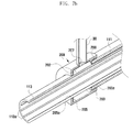
- FIG. 7A is a perspective view illustrating a separated double pipe coupled to the connector of FIG. 3A
- FIG. 7B is a perspective view illustrating a separated double pipe coupled to the connector of FIG. 3B .
- a double pipe heat exchanger of the present exemplary embodiment includes a separated double pipe 100 and each of connectors 20 and 200 of the foregoing exemplary embodiment coupled to an end portion of the separated double pipe 100.
- the connectors 20 and 200 have been described in the foregoing exemplary embodiment and therefore a detailed description thereof is omitted.
- the outer pipe 111 moves to a coupling position of the connector 200 along an outer circumferential surface of the inner pipe 113.
- the connectors 20 and 200 are coupled to the outer pipe 111 through outer pipe openings 23a and 203a of outer pipe couplers 23 and 203, and are coupled to the inner pipe 113 through inner pipe openings 25a and 205a such that the inner pipe 113 extends to the outside of the connectors 20 and 200 through inner pipe openings 25a and 205a.
- the outer pipe 111 and the inner pipe 113 are coupled, by welding both ends of each of the connectors 20 and 200, they are fixed and leakage of a solvent is prevented.
- the outer pipe 11 In the integral double pipe 10, in order to expose the inner pipe 13, the outer pipe 11 should be cut, however in the separated double pipe 100, the outer pipe 11 moves along an outer circumferential surface of the inner pipe 13, and thus it is unnecessary to cut the outer pipe 111.
- Each of spaces 22 and 202 to be connected to an outer pipe flow path 2a (see FIG. 5 ) of the separated double pipe 100 without cutting the outer pipe 11 is formed.
- a length of the outer pipe 111 is shorter than that of the inner pipe 113.
- An outer refrigerant pipe 30 is coupled to each of the external insertion holes 27 and 207 of each of the connectors 20 and 200 coupled to both sides of the separated double pipe 100.
- a gas refrigerant of a low temperature and a low pressure flows in an opposite direction and thus heat exchange can be performed.
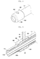
- FIG. 8 is a perspective view illustrating an integral connector formed in an outer pipe of the separated double pipe
- FIG. 9 is a perspective view illustrating a separated double pipe having the integral connector of FIG. 8 .
- an expanded pipe portion 503 having an inner diameter larger than that of the outer pipe 111 is integrally formed.
- An integral connector 500 is formed in the separated double pipe 100 by the expanded pipe portion 503.
- the integral connector 500 includes an expanded pipe portion 503 integrally formed from an end portion of the outer pipe 111 and having a diameter greater than an outer diameter of the outer pipe 111 and having an inner space 501, and a reduced pipe portion 505 having the reduced other end to couple to the outer circumference of the inner pipe 113 and having an inner pipe opening 505a, and an external insertion hole 507 for inserting an outer circumferential surface toward the inner space 501.
- the inner pipe 113 is inserted through the inner pipe opening 505a of the reduced pipe portion 505 of the integral connector 500, and by welding an end portion of the reduced pipe portion 505, they are fixed and leakage of a solvent is prevented.
- the outer refrigerant pipe 30 is coupled to the external insertion hole 507 of the integral connector 500.
- a circulation path of a refrigerant has been described above and therefore a detailed description thereof is omitted.
- the integral connector 500 of FIG. 8 has the same shape as that of the connector 20 of FIG. 3A , however may have the same shape as that of the connector 200 of FIG. 3B .
- cooling efficiency of a cooling system can be improved.
Landscapes
- Engineering & Computer Science (AREA)
- Physics & Mathematics (AREA)
- Thermal Sciences (AREA)
- Mechanical Engineering (AREA)
- General Engineering & Computer Science (AREA)
- Geometry (AREA)
- Heat-Exchange Devices With Radiators And Conduit Assemblies (AREA)
Abstract
Description
- The present invention relates to a double pipe and a heat exchanger having the same, and more particularly, to a double pipe and a heat exchanger having the same that can improve heat exchange efficiency of a heat exchanger by providing a double pipe structure having an excellent thermal conductivity performance.
- A vehicle air conditioner is installed in a vehicle to send a cold air into a vehicle room, thereby cooling the vehicle.
- A general air conditioning system of such an air conditioner has a freezing cycle formed by connecting, to a refrigerant pipe, a compressor for compressing and sending a refrigerant, a condenser for condensing a high pressure of refrigerant sent from the compressor, an expansion valve for depressurizing a refrigerant condensed and liquefied in the condenser, and an evaporator for cooling air ejected into a vehicle room with an endothermic reaction by an evaporation latent heat of a refrigerant by exchanging a heat of a low pressure of liquid refrigerant depressurized by the expansion valve with a heat of air to be sent into the vehicle room and by evaporating the refrigerant, and cools the vehicle room through a refrigerant circulation process.
- In order to improve a performance of an air conditioner, an apparatus that can supercool a liquid refrigerant of a high temperature and a high pressure expanded by an expansion valve and that can appropriately adjust a superheat degree of a refrigerant discharged in an evaporator is necessary, and therefore a recently developing cooling system has a predetermined internal heat exchanger in an expansion valve inhalation side and a compressor inhalation side. Such an internal heat exchanger has a double pipe structure and includes an inner pipe connected between a compression pipe in an evaporator and an outer pipe connected between a condenser and an expansion valve.
- Agas refrigerant of a low temperature and a low pressure flows in the inner pipe, and a liquid refrigerant of a high temperature and a high pressure flows in the outer pipe, and they flow in an opposite direction to exchange a heat thereof. That is, a temperature is appropriately adjusted by exchanging a heat of a liquid refrigerant of a high temperature and a high pressure injected into an expansion valve and a heat of a gas refrigerant of a low temperature and a low pressure discharged from an evaporator.
- When a heat transfer rate of such an internal heat exchanger increases, heat exchange efficiency thereof increases and is largely influenced by a structure of a double pipe.
- In order to limit a discharge of greenhouse gas to the atmosphere, a hydro fluoro carbon (HFC)-based 134a (R134a) refrigerant, which is a presently used global warming material will be replaced with a hydro fluoro olefin (HFO)-based 1234yf refrigerant, which is a low global warming material, and the 1234yf refrigerant to be a replacement in the future has a performance about 15% lower than R134a, which is a present refrigerant in an existing heat exchanger.
- In order to improve a lacking refrigerant performance, elements constituting an air conditioner, such as a compressor, an evaporator, and a condenser should be improved, however in order to improve the elements, much cost is required.
- Therefore, in order to improve efficiency and performance of a vehicle air conditioning system according to a refrigerant change, it is necessary to improve deterioration in performance of a heat exchanger.
- The present invention has been made in view of the above problems, and provides a double pipe and a heat exchanger having the same that can improve cooling efficiency of a cooling system by improving heat exchange efficiency of a heat exchanger by a double pipe structure.
- In accordance with an aspect of the present invention, a double pipe including an outer pipe and an inner pipe formed within the outer pipe includes: a plurality of barrier ribs formed in a length direction and disposed at a predetermined distance in a circumferential direction between the outer pipe and the inner pipe; and a plurality of protruding portions formed at positions corresponding to each of the plurality of barrier ribs and protruded in a center direction and formed in a length direction of the inner pipe from an inner circumferential surface of the inner pipe.
- In accordance with another aspect of the present invention, a double pipe heat exchanger includes: a double pipe including a plurality of barrier ribs formed in a length direction and disposed at a predetermined distance in a circumferential direction between an outer pipe and an inner pipe, and a plurality of protruding portions formed at positions corresponding to each of the plurality of barrier ribs and protruded in a center direction and formed in a length direction of the inner pipe from an inner circumferential surface of the inner pipe; and a connector coupled to an end portion of the double pipe, wherein all the outer pipe, the inner pipe, the plurality of barrier ribs, and the plurality of protruding portions are integrally formed, and an outer pipe opening for inserting the double pipe is formed at one side of the connector, an inner pipe opening for inserting the other pipe having the same diameter as that of the inner pipe of the double pipe is formed at the other side of the connector, and space to be connected to an outer pipe flow path formed between the inner pipe and the outer pipe of the double pipe is formed within the connector.
- The objects, features and advantages of the present invention will be more apparent from the following detailed description in conjunction with the accompanying drawings, in which:
-
FIG. 1 is a perspective view illustrating an integral double pipe of a double pipe heat exchanger according to an exemplary embodiment of the present invention; -
FIGS. 2A to 2D are perspective views illustrating modified examples of the integral double pipe ofFIG. 1 ; -
FIG. 3A is a perspective view illustrating a connector of the double pipe heat exchanger ofFIG. 1 ; -
FIG. 3B is a perspective view illustrating a modified example of the connector ofFIG. 3A ; -
FIG. 4A is a perspective view illustrating an integral double pipe coupled to the connector ofFIG. 3A ; -
FIG. 4B is a perspective view illustrating an integral double pipe coupled to the connector ofFIG. 3B ; -
FIG. 5 is a perspective view illustrating a separated double pipe of a double pipe heat exchanger according to another exemplary embodiment of the present invention; -
FIGS. 6A and6B are perspective views illustrating modified examples of the separated double pipe ofFIG. 5 ; -
FIG. 7A is a perspective view illustrating a separated double pipe coupled to the connector ofFIG. 3A ; -
FIG. 7B is a perspective view illustrating a separated double pipe coupled to the connector ofFIG. 3B ; -
FIG. 8 is a perspective view illustrating an integral connector formed in an outer pipe of the separated double pipe ofFIG. 5 ; and -
FIG. 9 is a perspective view illustrating a separated double pipe having the integral connector ofFIG. 8 . - Hereinafter, exemplary embodiments of the present invention are described in detail with reference to the accompanying drawings. The same reference numbers are used throughout the drawings to refer to the same or like parts. The views in the drawings are schematic views only, and are not intended to be to scale or correctly proportioned. Detailed descriptions of well-known functions and structures incorporated herein may be omitted to avoid obscuring the subject matter of the present invention.
-
FIG. 1 is a perspective view illustrating an integral double pipe of a double pipe heat exchanger according to an exemplary embodiment of the present invention, andFIGS. 2A to 2D are perspective views illustratingmodifiedexamples of the integral double pipe ofFIG. 1 . - Referring to
FIGS. 1 and2 , an integraldouble pipe 10 according to the present exemplary embodiment includes anouter pipe 11 and aninner pipe 13. - The integral
double pipe 10 includes a plurality ofbarrier ribs 11a formed in a length direction and disposed at a predetermined distance in a circumferential direction between theouter pipe 11 and theinner pipe 13, and a plurality of protrudingportions 13a formed at a position corresponding to each of the plurality ofbarrier ribs 11a and protruded in a center direction and formed in a length direction of an inner pipe from an inner circumferential surface of theinner pipe 13. - The
outer pipe 11, the plurality of barrier ribs 11a, theinner pipe 13, and the plurality of protrudingportions 13a are integrally formed. - Agas refrigerant of a low temperature and a low pressure flows in the
inner pipe 13, a liquid refrigerant of a high temperature and a high pressure flows in theouter pipe 11, and the refrigerants flow in an opposite direction to exchange a heat thereof. - A liquid refrigerant of a high temperature and a high pressure flows in an outer
pipe flow path 2 formed between theouter pipe 11 and theinner pipe 13. - Agas refrigerant of a low temperature and a low pressure flows in an inner
pipe flow path 3 formed in theinner pipe 13. - Both the
outer pipe 11 and theinner pipe 13 of the integraldouble pipe 10 have a circular sectional shape, however a shape of theouter pipe 11 and theinner pipe 13 of the integraldouble pipe 10 is not limited thereto and theouter pipe 11 and theinner pipe 13 can have various polygonal shapes such as a quadrangle, oval, and triangle. - The
barrier rib 11a and theprotruding portion 13a have a rectangular sectional shape, but a shape of thebarrier rib 11a and the protrudingportion 13a is not limited thereto and thebarrier rib 11a and the protrudingportion 13a can have a polygonal shape such as a circle, oval, and triangle. - For example, an inner diameter of the
outer pipe 11 is 22mm and a thickness thereof is about 3mm, and an inner diameter of theinner pipe 13 is 17mm and a thickness thereof is about 2.4mm. - A sectional thickness and height of the
barrier rib 11a and the protrudingportion 13a are about 1 mm. A cylindrical angle formed between thebarrier rib 11a and the protrudingportion 13a and anext barrier rib 11a and a next protrudingportion 13a is about 10 to 30°. -
FIGS. 2A to 2D illustrate modified examples of the integraldouble pipe 10 ofFIG. 1 . - Referring to
FIG. 2A , a plurality ofgrooves 11b are formed in a length direction at a predetermined distance in a circumferential direction of an outer circumferential surface of theouter pipe 11. - Referring to
FIG. 2B , additional protrudingportion 13b is formed between two adjacent protrudingportions 13a of a plurality of protrudingportions 13a of theinner pipe 13. - Referring to
FIG. 2C , in at least one of an outer circumferential surface and an inner circumferential surface of theinner pipe 13, anuneven portion 13c is formed in a portion in which the plurality of protrudingportions 13a are not formed. - In
FIG. 2C , theuneven portion 13c is formed in both an outer circumferential surface and an inner circumferential surface of theinner pipe 13, however may be formed only in an outer circumferential surface or an inner circumferential surface of theinner pipe 13. Further, instead of additional protrudingportion 13b ofFIG. 2B , anuneven portion 13c may be formed. - Referring to
FIG. 2D , anuneven portion 13d is formed in a surface of the protrudingportion 13a of theinner pipe 13. - In
FIG. 2D , theuneven portion 13d is formed in the protrudingportion 13a of theinner pipe 13, however theuneven portion 13d may be formed in the additional protrudingportion 13b of theinner pipe 13 ofFIG. 2B . - Further, the
uneven portion 13d may be formed in a plurality ofbarrier ribs 11a formed between theouter pipe 11 and theinner pipe 13. - A refrigerant flowing to the integral
double pipe 10 may be hydro fluoro olefin (HFO)-based 1234yf. - In an exemplary embodiment and modified examples of such a double pipe, when the refrigerant 1234yf to be used in the future having a higher specific volume than that of a presently used refrigerant, for example a refrigerant R134a is used, a sectional area is formed by a plurality of protruding
portions 13a and a plurality ofbarrier ribs 11a and thus thermal efficiency can be maximized, and thicknesses of the outer pipe and the inner pipe can be minimized. - The integral
double pipe 10 is made of one of aluminum, iron, plastic, and stainless steel. -
FIG. 3A is a perspective view illustrating a connector of the double pipe heat exchanger ofFIG. 1 ,FIG. 3B is a perspective view illustrating a modified example of the connector ofFIG. 3A ,FIG. 4A is a perspective view illustrating an integral double pipe coupled to the connector ofFIG. 3A , andFIG. 4B is a perspective view illustrating an integral double pipe coupled to the connector ofFIG. 3B . - Referring to
FIGS. 3A and4A , a double pipe heat exchanger according to the present exemplary embodiment includes an integraldouble pipe 10 and aconnector 20 coupled to an end portion of the integraldouble pipe 10. - At one side of the
connector 20, anouter pipe opening 23a for inserting the integraldouble pipe 10 is formed and at the other side thereof, aninner pipe opening 25a for inserting another pipe (13) having the same a diameter as that of theinner pipe 13 of the integraldouble pipe 10 is formed, and in an inner part thereof, aspace 22 to be connected to a flow path between theinner pipe 13 and theouter pipe 11 of the integraldouble pipe 10 is formed. - The
connector 20 is described in detail hereinafter. - Referring to
FIG. 3A , the inside of theconnector 20 is hollow, and theconnector 20 includes anouter pipe coupler 23 formed at one end of theconnector 20 and having anouter pipe opening 23a for inserting and coupling theouter pipe 11, aninner pipe coupler 25 formed at the other end of theconnector 20 and having aninner pipe opening 25a for inserting theinner pipe 13 and for coupling it to an outer circumference of theinner pipe 13, and anexternal penetration hole 27 for inserting an outer circumferential surface between theouter pipe coupler 23 and theinner pipe coupler 25. Theinner pipe 13 integrally formed with theouter pipe 11 and anotherinner pipe 13 inserted through theinner pipe opening 25a from the outside are coupled by welding within theconnector 20. - Referring to
FIGS. 3B and4B , the inside of theconnector 200 in which theconnector 20 ofFIGS. 3A and4A is modified is hollow, and theconnector 200 includes anouter pipe coupler 203 formed at one end of theconnector 20 and having anouter pipe opening 203a for inserting and coupling theouter pipe 11, aninner pipe coupler 205 formed at the other end of theconnector 200 and having aninner pipe opening 205a for inserting theinner pipe 13 and for coupling it to the outer circumference of theinner pipe 13, and anexternal penetration hole 207 for inserting an outer circumferential surface between theouter pipe coupler 203 and theinner pipe coupler 205. - A difference between the
connector 20 ofFIG. 3A and theconnector 200 ofFIG. 3B is that theconnector 20 ofFIG. 3A has a reduced outer circumferential diameter as advancing to theinner pipe coupler 25, whereas theconnector 200 ofFIG. 3B has the same outer circumferential diameter in theinner pipe coupler 205 and theouter pipe coupler 203. - Referring to
FIGS. 3A ,3B ,4A , and4B ,spaces FIG. 1 ) of the integraldouble pipe 10 and the external penetration holes 27 and 207 are formed at the inside between theouter pipe couplers inner pipe couplers connectors pipe flow path 2 are connected through thespaces - In the
connectors outer pipe 11, latchjaws outer pipe couplers - Therefore, the
connectors outer pipe 111 throughouter pipe openings outer pipe couplers inner pipe 113 throughinner pipe openings inner pipe 113 extends to the outside of theconnectors inner pipe openings outer pipe 11 and theinner pipe 13 are coupled, by welding both ends of each of theconnectors - Each of the
connectors double pipe 10, and anouter refrigerant pipe 30 is coupled to each of the external penetration holes 27 and 207 of each of theconnectors double pipe 10. Theouter refrigerant pipe 30 is coupled by welding. - Therefore, a closed loop is formed in the
outer pipe 11 by each of theconnectors double pipe 10 and each of theconnectors pipe flow path 2 via each ofspaces outer refrigerant pipe 30 coupled to each of the external insertion holes 27 and 207. - In the
inner pipe 13, a gas refrigerant of a low temperature and a low pressure flows in an opposite direction and thus heat exchange can be performed. -
FIG. 5 is a perspective view illustrating a separated double pipe of a double pipe heat exchanger according to another exemplary embodiment of the present invention, andFIGS. 6A and6B are perspective views illustrating modified examples of the separated double pipe ofFIG. 5 . - Referring to
FIGS. 5, 6A , and6B , unlike the integraldouble pipe 10 of the foregoing exemplary embodiment, in a separateddouble pipe 100 according to the present exemplary embodiment, anouter pipe 111 and aninner pipe 113 are separated. - The separated
double pipe 100 includes a plurality of first protrudingportions 111a and a plurality of second protrudingportions 113a. The plurality of first protrudingportions 111a are disposed between theouter pipe 111 and theinner pipe 113, formed in a length direction and disposed at a predetermined distance in a circumferential direction in one of an inner circumferential surface of theinner pipe 113 and an outer circumferential surface of theinner pipe 113. The plurality of second protrudingportions 113a are formed at positions corresponding to each of the plurality of first protrudingportions 111a and protruded in a center direction and formed in a length direction of theinner pipe 113 from an inner circumferential surface of theinner pipe 113. - As in the integral
double pipe 10 of the foregoing exemplary embodiment, a liquid refrigerant of a high temperature and a high pressure flows in an outerpipe flow path 2a formed between theouter pipe 111 and theinner pipe 113. - A gas refrigerant of a low temperature and a low pressure flows an inner
pipe flow path 3a formed in theinner pipe 113. -
FIGS. 6A and6B illustrate modified examples of the separateddouble pipe 100 ofFIG. 5 . - Referring to
FIG. 6A , a first protrudingportion 111a formed in an inner circumferential surface of theouter pipe 111 ofFIG. 5 is formed in an outer circumferential surface of theinner pipe 113. - The first protruding
portion 111a and the second protrudingportions 113a are alternately disposed. - Referring to
FIG. 6B , in at least one of an outer circumferential surface and an inner circumferential surface of theinner pipe 113, anuneven portion 113b is formed in a portion in which the second protrudingportion 113a is not formed, as shown inFIG. 2C . - In
FIG. 6B , theuneven portion 113b is formed in both an outer circumferential surface and an inner circumferential surface of theinner pipe 113, however it may be formed only in an outer circumferential surface or an inner circumferential surface. - In addition to the above-described elements, a configuration of the present exemplary embodiment and modified examples thereof can be applied to the foregoing exemplary embodiment, and a configuration the foregoing exemplary embodiment and modified examples thereof can be applied to the present exemplary embodiment.
- The separated
double pipe 100 is made of one of aluminum, iron, plastic, and stainless steel. - A refrigerant flowing the separated
double pipe 100 is HFO-based 1234yf. -
FIG. 7A is a perspective view illustrating a separated double pipe coupled to the connector ofFIG. 3A , andFIG. 7B is a perspective view illustrating a separated double pipe coupled to the connector ofFIG. 3B . - Referring to
FIGS. 3A ,3B ,7A , and7B , a double pipe heat exchanger of the present exemplary embodiment includes a separateddouble pipe 100 and each ofconnectors double pipe 100. - The
connectors - In order to insert the
connectors outer pipe 111 is coupled to theinner pipe 113, theouter pipe 111 moves to a coupling position of theconnector 200 along an outer circumferential surface of theinner pipe 113. - Therefore, the
connectors outer pipe 111 throughouter pipe openings outer pipe couplers inner pipe 113 throughinner pipe openings inner pipe 113 extends to the outside of theconnectors inner pipe openings outer pipe 111 and theinner pipe 113 are coupled, by welding both ends of each of theconnectors - In the integral
double pipe 10, in order to expose theinner pipe 13, theouter pipe 11 should be cut, however in the separateddouble pipe 100, theouter pipe 11 moves along an outer circumferential surface of theinner pipe 13, and thus it is unnecessary to cut theouter pipe 111. Each ofspaces pipe flow path 2a (seeFIG. 5 ) of the separateddouble pipe 100 without cutting theouter pipe 11 is formed. A length of theouter pipe 111 is shorter than that of theinner pipe 113. - An outer
refrigerant pipe 30 is coupled to each of the external insertion holes 27 and 207 of each of theconnectors double pipe 100. - Therefore, as in the integral
double pipe 10, by each of theconnectors double pipe 10 and coupled to the other side of the integraldouble pipe 10, a closed loop is formed in theouter pipe 111, and a liquid refrigerant of a high temperature and a high pressure flows through theouter refrigerant pipe 30 coupled to each of the external insertion holes 27 and 207. - In the
inner pipe 113, a gas refrigerant of a low temperature and a low pressure flows in an opposite direction and thus heat exchange can be performed. -
FIG. 8 is a perspective view illustrating an integral connector formed in an outer pipe of the separated double pipe, andFIG. 9 is a perspective view illustrating a separated double pipe having the integral connector ofFIG. 8 . - Referring to
FIGS. 8 and 9 , in both end portions of theouter pipe 111 of the separateddouble pipe 100 of the present exemplary embodiment, an expandedpipe portion 503 having an inner diameter larger than that of theouter pipe 111 is integrally formed. - An
integral connector 500 is formed in the separateddouble pipe 100 by the expandedpipe portion 503. - The
integral connector 500 includes an expandedpipe portion 503 integrally formed from an end portion of theouter pipe 111 and having a diameter greater than an outer diameter of theouter pipe 111 and having aninner space 501, and a reducedpipe portion 505 having the reduced other end to couple to the outer circumference of theinner pipe 113 and having aninner pipe opening 505a, and anexternal insertion hole 507 for inserting an outer circumferential surface toward theinner space 501. - The
inner pipe 113 is inserted through theinner pipe opening 505a of the reducedpipe portion 505 of theintegral connector 500, and by welding an end portion of the reducedpipe portion 505, they are fixed and leakage of a solvent is prevented. - The
outer refrigerant pipe 30 is coupled to theexternal insertion hole 507 of theintegral connector 500. A circulation path of a refrigerant has been described above and therefore a detailed description thereof is omitted. - The
integral connector 500 ofFIG. 8 has the same shape as that of theconnector 20 ofFIG. 3A , however may have the same shape as that of theconnector 200 ofFIG. 3B . - As described above, according to the present invention, by improving a thermal conductivity of a refrigerant by a double pipe structure, efficiency and performance of a vehicle air conditioning system can be improved.
- By the double pipe structure, a thickness of the outer pipe and the inner pipe can be minimized.
- By improving heat exchange efficiency by a heat exchanger having a double pipe, cooling efficiency of a cooling system can be improved.
- Although exemplary embodiments of the present invention have been described in detail hereinabove, it should be clearly understood that many variations and modifications of the basic inventive concepts herein described, which may appear to those skilled in the art, will still fall within the spirit and scope of the exemplary embodiments of the present invention as defined in the appended claims.
Claims (10)
- A double pipe comprising an outer pipe and an inner pipe formed within the outer pipe, comprising:a plurality of barrier ribs formed in a length direction and disposed at a predetermined distance in a circumferential direction between the outer pipe and the inner pipe; anda plurality of protruding portions formed at positions corresponding to each of the plurality of barrier ribs and protruded in a center direction and formed in a length direction of the inner pipe from an inner circumferential surface of the inner pipe.
- The double pipe of claim 1, wherein all the outer pipe, the inner pipe, the plurality of barrier ribs, and the plurality of protruding portions are integrally formed.
- The double pipe of claim 1, wherein a plurality of grooves formed in a length direction and disposed at a predetermined distance in a circumferential direction are formed in an outer circumferential surface of the outer pipe.
- The double pipe of claim 1, wherein an additional protruding portion is formed between two adjacent protruding portions of the plurality of protruding portions.
- The double pipe of claim 1, wherein in at least one of an outer circumferential surface and an inner circumferential surface of the inner pipe, an uneven portion is formed in a portion in which the plurality of protruding portions are not formed.
- The double pipe of any one of claims 1 to 4, wherein an uneven portion is formed in a surface of the protruding portion.
- A double pipe heat exchanger having a double pipe of any one of claims 1 to 6, the double pipe heat exchanger further comprising:a connector coupled to an end portion of the double pipe,wherein all the outer pipe, the inner pipe, the plurality of barrier ribs, and the plurality of protruding portions are integrally formed, andan outer pipe opening for inserting the double pipe is formed at one side of the connector, an inner pipe opening for inserting the other pipe having the same diameter as that of the inner pipe of the double pipe is formed at the other side of the connector, and space to be connected to an outer pipe flow path formed between the inner pipe and the outer pipe of the double pipe is formed within the connector.
- A double pipe comprising an outer pipe and an inner pipe formed within the outer pipe, comprising:a plurality of first protruding portions formed in a length direction and disposed at a predetermined distance in a circumferential direction in one of an inner circumferential surface of the outer pipe and an outer circumferential surface of the inner pipe, between the outer pipe and the inner pipe; anda plurality of second protruding portions formed at positions corresponding to each of the first protruding portions and protruded in a central direction and formed in a length direction of the inner pipe from an inner circumferential surface of the inner pipe.
- The double pipe of claim 8, wherein an expanded pipe portion having an inner diameter greater than that of the outer pipe is integrally formed in both end portions of the outer pipe.
- A double pipe heat exchanger comprising the double pipe of claims 8 or 9.
Applications Claiming Priority (1)
| Application Number | Priority Date | Filing Date | Title |
|---|---|---|---|
| KR1020100019822A KR101166806B1 (en) | 2010-03-05 | 2010-03-05 | Double tube and heat exchanger having same |
Publications (2)
| Publication Number | Publication Date |
|---|---|
| EP2363675A2 true EP2363675A2 (en) | 2011-09-07 |
| EP2363675A3 EP2363675A3 (en) | 2013-03-06 |
Family
ID=43131836
Family Applications (1)
| Application Number | Title | Priority Date | Filing Date |
|---|---|---|---|
| EP20110150834 Withdrawn EP2363675A3 (en) | 2010-03-05 | 2011-01-13 | Double pipe and heat exchanger having the same |
Country Status (4)
| Country | Link |
|---|---|
| US (1) | US20110214847A1 (en) |
| EP (1) | EP2363675A3 (en) |
| KR (1) | KR101166806B1 (en) |
| CN (1) | CN102192670A (en) |
Cited By (1)
| Publication number | Priority date | Publication date | Assignee | Title |
|---|---|---|---|---|
| WO2013070450A1 (en) * | 2011-11-08 | 2013-05-16 | Carrier Corporation | Heat exchanger and method of making thereof |
Families Citing this family (28)
| Publication number | Priority date | Publication date | Assignee | Title |
|---|---|---|---|---|
| KR101200597B1 (en) * | 2010-12-24 | 2012-11-12 | 엘지전자 주식회사 | A complex pipe for transferring heat, heat exchanging system and heat exchanger using the same |
| ITTO20110392A1 (en) * | 2011-05-03 | 2012-11-04 | Dytech Dynamic Fluid Tech Spa | HEAT EXCHANGER PREFERABLY FOR A CIRCUIT OF A VEHICLE |
| JP5916330B2 (en) * | 2011-10-04 | 2016-05-11 | 株式会社Uacj銅管 | Heat exchanger tube for supercooler and supercooler using the same |
| KR101211637B1 (en) | 2011-12-12 | 2012-12-18 | 주식회사 화승알앤에이 | Double pipe heat exchanger having multi-directional connector and air conditioner for vehicle having the same |
| EP2653765B1 (en) * | 2012-04-20 | 2019-02-27 | TI Automotive (Heidelberg) GmbH | Pipe for a fluid to be warmed up |
| CN103629952B (en) * | 2012-08-29 | 2016-05-18 | 洛阳麦达斯铝业有限公司 | Duct type heat exchanger, its manufacture method and heat transmission equipment |
| KR101249721B1 (en) * | 2012-09-05 | 2013-04-02 | 주식회사 화승알앤에이 | Dual pipe for heat exchange |
| CN102840399B (en) * | 2012-09-11 | 2014-12-24 | 精工管业(杭州)有限公司 | Duel-channel steel-plastic complex pipe |
| DE102012022363A1 (en) * | 2012-11-15 | 2014-05-15 | GM Global Technology Operations LLC (n. d. Gesetzen des Staates Delaware) | Internal heat exchanger for a motor vehicle air conditioning system |
| US10557667B2 (en) * | 2013-04-30 | 2020-02-11 | Carrier Corporation | Refrigerant to water heat exchanger |
| KR101335872B1 (en) * | 2013-05-28 | 2013-12-02 | 박용철 | Method for manufacturing pipe and apparatus for manufacturing therefor |
| EP3086011B1 (en) * | 2015-04-21 | 2019-07-31 | Airbus Operations GmbH | Double-walled pipe with integrated heating capability for an aircraft or spacecraft |
| US10508867B2 (en) * | 2015-05-28 | 2019-12-17 | Dometic Sweden Ab | Corrosion resistant coaxial heat exchanger assembly |
| CN105135925A (en) * | 2015-09-24 | 2015-12-09 | 江苏广通管业制造有限公司 | Cooling bellows |
| CN106679240A (en) * | 2015-11-11 | 2017-05-17 | 丹佛斯微通道换热器(嘉兴)有限公司 | Heat exchangers and tubes |
| EP3301199B1 (en) * | 2016-03-28 | 2021-01-20 | LG Electronics Inc. -1- | Bent pipe made of stainless steel |
| CN108071445A (en) * | 2016-11-11 | 2018-05-25 | 上海汽车集团股份有限公司 | Crankcase anti-icing equipment, crankcase ventilation system, engine and automobile |
| CN110006274A (en) * | 2018-01-04 | 2019-07-12 | 日本碍子株式会社 | Heat-exchanging part and heat exchanger |
| JP2021103009A (en) * | 2019-12-24 | 2021-07-15 | 株式会社Lixil | Hot water supply system and heat exchange device |
| FR3106201B1 (en) * | 2020-01-09 | 2022-11-11 | Hutchinson | WATERPROOF CONNECTION OF A CONNECTOR TO A COAXIAL TUBULAR HEAT EXCHANGER |
| EP4113036A4 (en) * | 2020-03-12 | 2023-08-09 | Zhejiang Dunan Artificial Environment Co., Ltd. | THREE-WAY TUBE, HEAT EXCHANGER, HEAT EXCHANGER ASSEMBLY AND REFRIGERATION DEVICE |
| US11920874B2 (en) * | 2021-02-09 | 2024-03-05 | Ngk Insulators, Ltd. | Heat exchange member, heat exchanger and heat conductive member |
| CN114279249A (en) * | 2021-12-29 | 2022-04-05 | 思安新能源股份有限公司 | Double-channel sleeve type heat exchange and storage structure and using method thereof |
| CN114471439B (en) * | 2022-02-28 | 2024-10-29 | 茂名重力石化装备股份公司 | String pipe reactor with static fit jacket |
| CN114659390B (en) * | 2022-03-22 | 2023-12-15 | 四川奥格莱能源科技有限公司 | Bidirectional double-layer enhanced heat transfer tube heat exchanger |
| CN116096044B (en) * | 2023-01-13 | 2026-01-06 | 江苏海迪威液压有限公司 | A water cooling system for a converter |
| KR20250127964A (en) * | 2024-02-20 | 2025-08-27 | 지성알미늄주식회사 | Integrated pipe for heat exchange |
| DE102024002556A1 (en) | 2024-08-07 | 2026-02-12 | Wieland-Werke Aktiengesellschaft | Coaxial heat exchanger and circuit with a coaxial heat exchanger |
Family Cites Families (15)
| Publication number | Priority date | Publication date | Assignee | Title |
|---|---|---|---|---|
| FR362995A (en) * | 1906-02-05 | 1906-07-18 | Paul Determes | Double finned tubes for heating or cooling liquids |
| FR2545594A1 (en) * | 1983-05-05 | 1984-11-09 | Scoma Energie | Heat exchanger |
| JPH064221Y2 (en) | 1987-05-21 | 1994-02-02 | 三菱電機株式会社 | Heat exchanger |
| DE4116692A1 (en) * | 1991-05-22 | 1992-11-26 | Kreis Truma Geraetebau | HEAT EXCHANGER INSERT FOR AIR HEATERS |
| JPH10339588A (en) | 1997-06-06 | 1998-12-22 | Denso Corp | Heat exchanger and its manufacturing method |
| JP3996300B2 (en) * | 1999-07-02 | 2007-10-24 | 株式会社コロナ | Heat exchanger |
| JP2002243380A (en) | 2001-02-16 | 2002-08-28 | Hitachi Ltd | Absorption chiller / heater |
| WO2003085344A1 (en) * | 2002-04-08 | 2003-10-16 | Norsk Hydro Asa | Heat exchanger assembly |
| CN2736729Y (en) * | 2003-03-28 | 2005-10-26 | 中国科学院理化技术研究所 | Miniature compact type deep cooling counter-flow heat exchanger |
| CN1546931A (en) * | 2003-12-12 | 2004-11-17 | 上海理工大学 | Composite rib casing heat exchanger |
| CN2771785Y (en) * | 2005-02-07 | 2006-04-12 | 邹昌校 | Sleeving-pipe type heat exchanger |
| DE102007015186A1 (en) * | 2007-03-29 | 2008-10-02 | Valeo Klimasysteme Gmbh | Internal heat exchanger for an air conditioner |
| JP2009041798A (en) * | 2007-08-07 | 2009-02-26 | Showa Denko Kk | Heat exchanger |
| JP2009162395A (en) | 2007-12-28 | 2009-07-23 | Showa Denko Kk | Double-wall-tube heat exchanger |
| JP5202030B2 (en) * | 2008-02-26 | 2013-06-05 | 株式会社ケーヒン・サーマル・テクノロジー | Double tube heat exchanger |
-
2010
- 2010-03-05 KR KR1020100019822A patent/KR101166806B1/en not_active Expired - Fee Related
- 2010-12-21 US US12/975,149 patent/US20110214847A1/en not_active Abandoned
-
2011
- 2011-01-13 EP EP20110150834 patent/EP2363675A3/en not_active Withdrawn
- 2011-01-28 CN CN2011100338809A patent/CN102192670A/en active Pending
Non-Patent Citations (1)
| Title |
|---|
| None |
Cited By (4)
| Publication number | Priority date | Publication date | Assignee | Title |
|---|---|---|---|---|
| WO2013070450A1 (en) * | 2011-11-08 | 2013-05-16 | Carrier Corporation | Heat exchanger and method of making thereof |
| US9943088B2 (en) | 2011-11-08 | 2018-04-17 | Carrier Corporation | Heat exchanger and method of making thereof |
| US10785992B2 (en) | 2011-11-08 | 2020-09-29 | Taylor Commercial Foodservice, Llc | Heat exchanger and method of making thereof |
| US11278040B2 (en) | 2011-11-08 | 2022-03-22 | Taylor Commercial Foodservice, Llc | Heat exchanger and method of making thereof |
Also Published As
| Publication number | Publication date |
|---|---|
| US20110214847A1 (en) | 2011-09-08 |
| EP2363675A3 (en) | 2013-03-06 |
| KR20100111610A (en) | 2010-10-15 |
| KR101166806B1 (en) | 2012-07-31 |
| CN102192670A (en) | 2011-09-21 |
Similar Documents
| Publication | Publication Date | Title |
|---|---|---|
| EP2363675A2 (en) | Double pipe and heat exchanger having the same | |
| US9513061B2 (en) | Dual pipe for heat exchange | |
| JP5777622B2 (en) | Heat exchanger, heat exchange method and refrigeration air conditioner | |
| KR101797176B1 (en) | Dual pipe structure for internal heat exchanger | |
| US20140069140A1 (en) | Accumulator heat exchanger | |
| JP2007032949A (en) | Heat exchanger | |
| JP5646257B2 (en) | Refrigeration cycle equipment | |
| US20060213220A1 (en) | Vehicular air-conditioner | |
| JP2009041798A (en) | Heat exchanger | |
| JP5540816B2 (en) | Evaporator unit | |
| JP2005049049A (en) | Heat exchanger | |
| JP5898892B2 (en) | Intermediate heat exchanger | |
| JP2001241806A (en) | Pressure-proof component, heat exchanger with pressure- proof component and freezer with pressure-proof component | |
| KR20120139007A (en) | Double-wall pipe type internal heat exchanger | |
| KR101389973B1 (en) | Heat exchange structure for capillary tube of refrigeration cycle | |
| US20140083664A1 (en) | Heat exchanger | |
| CN114207365A (en) | Water-cooled condenser | |
| JP2014095482A (en) | Double-pipe heat exchanger | |
| KR20160083440A (en) | Multiple pipe for refrigerator exchanger | |
| KR101314859B1 (en) | A method for manufacturing a heat exchanger | |
| CN216244609U (en) | Air conditioner | |
| JP2014035169A (en) | Intermediate heat exchanger | |
| KR20110004155A (en) | Chiller type air conditioner | |
| JP2010078256A (en) | Fin tube type heat exchanger, and refrigerating cycle device and air conditioner using the same | |
| WO2018168698A1 (en) | Heat exchanging device and heat exchanging method |
Legal Events
| Date | Code | Title | Description |
|---|---|---|---|
| PUAI | Public reference made under article 153(3) epc to a published international application that has entered the european phase |
Free format text: ORIGINAL CODE: 0009012 |
|
| AK | Designated contracting states |
Kind code of ref document: A2 Designated state(s): AL AT BE BG CH CY CZ DE DK EE ES FI FR GB GR HR HU IE IS IT LI LT LU LV MC MK MT NL NO PL PT RO RS SE SI SK SM TR |
|
| AX | Request for extension of the european patent |
Extension state: BA ME |
|
| PUAL | Search report despatched |
Free format text: ORIGINAL CODE: 0009013 |
|
| AK | Designated contracting states |
Kind code of ref document: A3 Designated state(s): AL AT BE BG CH CY CZ DE DK EE ES FI FR GB GR HR HU IE IS IT LI LT LU LV MC MK MT NL NO PL PT RO RS SE SI SK SM TR |
|
| AX | Request for extension of the european patent |
Extension state: BA ME |
|
| RIC1 | Information provided on ipc code assigned before grant |
Ipc: F28D 7/10 20060101AFI20130128BHEP Ipc: F28F 1/42 20060101ALI20130128BHEP Ipc: F28F 9/02 20060101ALI20130128BHEP Ipc: F28F 1/40 20060101ALI20130128BHEP |
|
| 17P | Request for examination filed |
Effective date: 20130905 |
|
| RBV | Designated contracting states (corrected) |
Designated state(s): AL AT BE BG CH CY CZ DE DK EE ES FI FR GB GR HR HU IE IS IT LI LT LU LV MC MK MT NL NO PL PT RO RS SE SI SK SM TR |
|
| 17Q | First examination report despatched |
Effective date: 20150518 |
|
| STAA | Information on the status of an ep patent application or granted ep patent |
Free format text: STATUS: THE APPLICATION IS DEEMED TO BE WITHDRAWN |
|
| 18D | Application deemed to be withdrawn |
Effective date: 20170530 |