EP2363692A2 - Verfahren und Anordnung zum Messen von Verfahrensparametern - Google Patents
Verfahren und Anordnung zum Messen von Verfahrensparametern Download PDFInfo
- Publication number
- EP2363692A2 EP2363692A2 EP20110152563 EP11152563A EP2363692A2 EP 2363692 A2 EP2363692 A2 EP 2363692A2 EP 20110152563 EP20110152563 EP 20110152563 EP 11152563 A EP11152563 A EP 11152563A EP 2363692 A2 EP2363692 A2 EP 2363692A2
- Authority
- EP
- European Patent Office
- Prior art keywords
- fluid
- flow
- airfoil
- edge
- pedestal
- Prior art date
- Legal status (The legal status is an assumption and is not a legal conclusion. Google has not performed a legal analysis and makes no representation as to the accuracy of the status listed.)
- Granted
Links
Images


Classifications
-
- G—PHYSICS
- G01—MEASURING; TESTING
- G01D—MEASURING NOT SPECIALLY ADAPTED FOR A SPECIFIC VARIABLE; ARRANGEMENTS FOR MEASURING TWO OR MORE VARIABLES NOT COVERED IN A SINGLE OTHER SUBCLASS; TARIFF METERING APPARATUS; MEASURING OR TESTING NOT OTHERWISE PROVIDED FOR
- G01D5/00—Mechanical means for transferring the output of a sensing member; Means for converting the output of a sensing member to another variable where the form or nature of the sensing member does not constrain the means for converting; Transducers not specially adapted for a specific variable
- G01D5/26—Mechanical means for transferring the output of a sensing member; Means for converting the output of a sensing member to another variable where the form or nature of the sensing member does not constrain the means for converting; Transducers not specially adapted for a specific variable characterised by optical transfer means, i.e. using infrared, visible, or ultraviolet light
- G01D5/28—Mechanical means for transferring the output of a sensing member; Means for converting the output of a sensing member to another variable where the form or nature of the sensing member does not constrain the means for converting; Transducers not specially adapted for a specific variable characterised by optical transfer means, i.e. using infrared, visible, or ultraviolet light with deflection of beams of light, e.g. for direct optical indication
- G01D5/30—Mechanical means for transferring the output of a sensing member; Means for converting the output of a sensing member to another variable where the form or nature of the sensing member does not constrain the means for converting; Transducers not specially adapted for a specific variable characterised by optical transfer means, i.e. using infrared, visible, or ultraviolet light with deflection of beams of light, e.g. for direct optical indication the beams of light being detected by photocells
-
- G—PHYSICS
- G01—MEASURING; TESTING
- G01F—MEASURING VOLUME, VOLUME FLOW, MASS FLOW OR LIQUID LEVEL; METERING BY VOLUME
- G01F1/00—Measuring the volume flow or mass flow of fluid or fluent solid material wherein the fluid passes through a meter in a continuous flow
- G01F1/05—Measuring the volume flow or mass flow of fluid or fluent solid material wherein the fluid passes through a meter in a continuous flow by using mechanical effects
- G01F1/20—Measuring the volume flow or mass flow of fluid or fluent solid material wherein the fluid passes through a meter in a continuous flow by using mechanical effects by detection of dynamic effects of the flow
- G01F1/32—Measuring the volume flow or mass flow of fluid or fluent solid material wherein the fluid passes through a meter in a continuous flow by using mechanical effects by detection of dynamic effects of the flow using swirl flowmeters
- G01F1/325—Means for detecting quantities used as proxy variables for swirl
- G01F1/3259—Means for detecting quantities used as proxy variables for swirl for detecting fluid pressure oscillations
-
- G—PHYSICS
- G01—MEASURING; TESTING
- G01K—MEASURING TEMPERATURE; MEASURING QUANTITY OF HEAT; THERMALLY-SENSITIVE ELEMENTS NOT OTHERWISE PROVIDED FOR
- G01K13/00—Thermometers specially adapted for specific purposes
- G01K13/02—Thermometers specially adapted for specific purposes for measuring temperature of moving fluids or granular materials capable of flow
- G01K13/024—Thermometers specially adapted for specific purposes for measuring temperature of moving fluids or granular materials capable of flow of moving gases
-
- G—PHYSICS
- G01—MEASURING; TESTING
- G01K—MEASURING TEMPERATURE; MEASURING QUANTITY OF HEAT; THERMALLY-SENSITIVE ELEMENTS NOT OTHERWISE PROVIDED FOR
- G01K13/00—Thermometers specially adapted for specific purposes
- G01K13/02—Thermometers specially adapted for specific purposes for measuring temperature of moving fluids or granular materials capable of flow
- G01K13/028—Thermometers specially adapted for specific purposes for measuring temperature of moving fluids or granular materials capable of flow for use in total air temperature [TAT] probes
Definitions
- At least some known sensors are susceptible to ice buildup due to their position and orientation in their environment.
- Some of these sensors use a heating system, for example, an electrical or pneumatic heating system, to prevent ice build up.
- a heating system for example, an electrical or pneumatic heating system
- the ice build up is due to the combination of water content in the fluid surrounding the sensor, the ambient temperature, and shape of the sensor.
- the heating system adds complexity, weight, and cost to the sensor, may affect sensor performance, and introduce errors into the sensor output.
- the errors may relate to a time response of the sensor, a recovery error, and because current sensors are designed for optimal performance at zero angle of attack airflow conditions, an error due an angle of attack of the sensor with respect to the flow past the sensor.
- a sensor assembly in one embodiment, includes a base, a pedestal including a body extending between a leading edge and a trailing edge in a direction of fluid flow past the body, a first edge of the pedestal coupled to the base, a second edge opposes the first edge.
- the sensor assembly also includes an airfoil extending from the pedestal, a leading edge of the airfoil aligned with the leading edge of the pedestal, the airfoil extending in a direction of a flow of fluid along the second edge.
- the sensor assembly further includes a sensor element extending from the second edge spaced apart from the airfoil by a first gap, and a shield at least partially surrounding the sensor element, the shield spaced apart from the airfoil by a second gap defining a fluid flow inlet to the sensor element.
- a method of sensing a process parameter includes positioning a process sensor assembly within a flow of fluid, the sensor assembly including a convex surface and an adjacent concave surface oriented serially in a direction of the flow of fluid, sampling a portion of the flow of fluid after the portion of the flow of fluid is decelerated by the concave surface, and channeling the portion of the flow of fluid to a sensor element shielded from direct impingement of the flow of fluid.
- a process sensing system in yet another embodiment, includes a fluid conveyor including a sidewall, a pedestal coupled to the sidewall, and an airfoil extending from the pedestal, the airfoil substantially symmetric about a longitudinal axis extending substantially in a direction of a flow of fluid through the fluid conveyor, the airfoil including a convex surface and a convex surface oriented serially in the direction of the flow of fluid.
- the process sensing system also includes a sensor element extending from the pedestal downstream of the airfoil, and a shield at least partially surrounding the sensor element, the shield spaced apart from the sensor element by a sensor flow channel, the shield spaced apart from the airfoil by a second gap defining a fluid flow inlet to the sensor element.
- FIG. 1 is a perspective view of a process sensor assembly 100 in accordance with an exemplary embodiment of the present invention.
- process sensor assembly 100 includes a base 102 coupled to a flange 104.
- Base 102 extends a height 106 away from flange 104.
- Height 106 is selected to substantially match a thickness of a sidewall of a fluid conveying member such as, but not limited to, a pipe and a gas turbine engine casing.
- Process sensor assembly 100 includes a pedestal 108 having a substantially triangular cross-section.
- Pedestal 108 includes a body 110 having substantially symmetric sidewalls 112 diverging between a knife-edge leading edge 114 and a respective trailing edge 116 in a direction 117 of a flow of fluid.
- a first edge 118 of pedestal 108 is coupled to base 102 and a second edge 120 opposes first edge 118.
- Process sensor assembly 100 includes an airfoil 122 extending from pedestal 108.
- a leading edge 124 of airfoil 122 is substantially aligned with leading edge 114 of pedestal 108.
- Airfoil 122 extends along edge 120 in direction 117 to respective trailing edges 126 separated by a concave trailing surface 128.
- airfoil 122 is symmetric about a centerline 130.
- Airfoil 122 includes a convex surface portion 132 upstream from a concave surface portion 134. Convex surface portion 132 extends from leading edge 124 to concave surface portion 134 and concave surface portion 134 extends from convex surface portion 132 to trailing edge 126.
- a profile of convex surface portion 132 and concave surface portion 134 is configured to channel liquid entrained in a fluid flowing over convex surface portion 132 and concave surface portion 134 away from fluid flow inlet 144 to sensor element 136.
- Pedestal 108 includes a height 133 between first edge 118 and second edge 120 wherein height 121 is selected to extend airfoil 122 into the flow of fluid beyond a boundary layer of the flow of fluid.
- a sensor element 136 extends from second edge 120 and is spaced apart from airfoil 122 by a first gap 138.
- a shield 140 at least partially surrounds sensor element 136.
- Shield 140 is spaced apart from trailing edge 126 by a second gap 142 defining a fluid flow inlet 144 to sensor element 136.
- shield 140 is formed of separate airfoils.
- shield 140 is formed of a single member configured to perform the functions described herein.
- a gap is maintained between shield 140 and sensor element 136 that defines a sensor flow channel 146.
- Pedestal 110 includes knife edge leading edge 114 and a trailing surface 148 having a width 150.
- Airfoil 122 includes a varying width between leading edge 124 and trailing edges 126 that is generally greater than width 150.
- Flange 104 is coupled to base 102.
- Flange 104 is configured to couple to a wall (not shown) of a fluid conveying member, such as, but not limited to a pipe and a gas turbine engine casing.
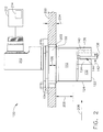
- FIG. 2 is a side elevation view of process sensor assembly 100 in accordance with an exemplary embodiment of the present invention.
- process sensor assembly 100 is couplable to a gas turbine engine casing 200 through an aperture 202.
- Height 106 substantially matches a thickness 204 of casing 200.
- Pedestal 110 includes height 133 selected to extend airfoil 122 into a flow of fluid 206 beyond a boundary layer 208 of flow of fluid 206.
- An electrical connection box 210 facilitates connecting electrical conduits between sensor element 136 and, for example, but not limited to, a control system 212 comprising a processor 214.
- process sensor assembly 100 is inserted into aperture 202 through engine casing 200 or other fluid conveying member.
- Pedestal 110 is selected based on positioning airfoil 122 and sensor element 136 away from engine casing 200 a distance sufficient for airfoil 122 and sensor element 136 to be beyond a boundary layer of fluid flow through engine casing 200.
- fluid flow past process sensor assembly 100 may contain entrained water, ice, and/or particulate matter.
- Water and ice impinging on pedestal 110 are shed quickly due to knife edge leading edge 114 and the narrow wedge shape of pedestal 110.
- Entrained ice and water passing airfoil 122 is accelerated by convex surface 132 and then decelerated by concave surface 134.
- the flow of fluid at the trailing edge of concave surface 134 is substantially stalled.
- because of the mass of the water and ice they can not decelerate quickly and is carried on past shield 140 and consequently can not enter fluid flow inlet 144.
- the stalled fluid flow because of its slow velocity is able to enter fluid flow inlet 114 aided by a low pressure volume generated proximate surface 128.
- the fluid is then directed through sensor flow channel 146, where sensor element 136 is able to interact with the fluid flow to determine one or more process parameters associated with the fluid flow.
- the fluid flow exits process sensor assembly 100 through exhaust port 300 (shown in Figure 3 ).
- Figure 3 is a perspective view of process sensor assembly 100 looking upstream.
- an exhaust port 300 is coupled in flow communication to fluid flow inlet 144 and sensor flow channel 146.
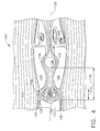
- FIG. 4 is a diagram indicating lines of flow of fluid past process sensor assembly 100 in accordance with an exemplary embodiment of the present invention.
- a bulk flow of fluid 400 flows past process sensor assembly 100.
- Bulk flow of fluid 400 flows past airfoil 122 which accelerates a portion (not shown in figure 4 ) of bulk flow of fluid 400 along convex surface portion 132 (not shown in Figure 4 ) and then decelerates bulk flow of fluid 400 along concave surface portion 134 such that a portion 402 of bulk flow of fluid 400 substantially stalls proximate fluid flow inlet 144.
- portion 402 is substantially free of any water droplets or particulate matter that can form into ice or Portion 402 is further facilitated being drawn into fluid flow inlet 144 by a low pressure area 404 formed at concave trailing surface 128.
- Portion 402 is channeled through sensor flow channel 146 where the parameter sensed by sensor element 136 is determined.
- sensor element 136 is a temperature sensor.
- sensor element 136 is other than a temperature sensor, for example, but not limited to, a pressure sensor, a differential pressure sensor, a flow sensor, a gas composition sensor, and a fluid chemistry sensor.
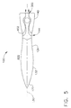
- Figure 5 is a diagram indicating lines of flow of fluid past process sensor assembly 100 in accordance with an exemplary embodiment of the present invention.
- bulk flow of fluid 400 flows past process sensor assembly 100 at a zero angle of attack.
- Surfaces 132 and 134 channel portion 402 through fluid flow inlet 144 and sensor flow channel 146 without exposing sensor element 136 to impingement or contact with water or particulates from bulk flow 400.
- Figure 6 is a diagram indicating lines of flow of fluid past process sensor assembly 100 in accordance with an exemplary embodiment of the present invention.
- bulk flow of fluid 400 flows past process sensor assembly 100 at a positive angle of attack 600.
- angle of attack 600 equals approximately 5°. In various other embodiments, angle of attack 600 equals an angle greater than approximately 5°.
- processor refers to central processing units, microprocessors, microcontrollers, reduced instruction set circuits (RISC), application specific integrated circuits (ASIC), logic circuits, and any other circuit or processor capable of executing the functions described herein.
- RISC reduced instruction set circuits
- ASIC application specific integrated circuits
- the terms "software” and “firmware” are interchangeable, and include any computer program stored in memory for execution by processor 214, including RAM memory, ROM memory, EPROM memory, EEPROM memory, and nonvolatile RAM (NVRAM) memory.
- RAM memory random access memory
- ROM memory read-only memory
- EPROM memory erasable programmable read-only memory
- EEPROM memory electrically erasable programmable read-only memory
- NVRAM nonvolatile RAM
- the above-described embodiments of the disclosure may be implemented using computer programming or engineering techniques including computer software, firmware, hardware or any combination or subset thereof, wherein the technical effect is for sensing a process parameters using an unheated sensor in a location where icing and water impingement may introduce errors in the value of the sensed parameter.
- Any such resulting program, having computer-readable code means may be embodied or provided within one or more computer-readable media, thereby making a computer program product, i.e., an article of manufacture, according to the discussed embodiments of the disclosure.
- the computer readable media may be, for example, but is not limited to, a fixed (hard) drive, diskette, optical disk, magnetic tape, semiconductor memory such as read-only memory (ROM), and/or any transmitting/receiving medium such as the Internet or other communication network or link.
- the article of manufacture containing the computer code may be made and/or used by executing the code directly from one medium, by copying the code from one medium to another medium, or by transmitting the code over a network.
- the above-described embodiments of a method and assembly for sensing a process parameter provides a cost-effective and reliable means for reducing effects of direct water and/or ice impingement on the sensor, angle of attack, and time response. More specifically, the methods and assembly described herein facilitate separating water and/or ice from a flow of fluid. In addition, the above-described methods and assembly facilitate sampling a low velocity portion of the flow of fluid without moving parts in the process sensor assembly. As a result, the methods and assembly described herein facilitate measuring parameters of a process in a cost-effective and reliable manner.
Landscapes
- Physics & Mathematics (AREA)
- General Physics & Mathematics (AREA)
- Fluid Mechanics (AREA)
- Measuring Volume Flow (AREA)
- Measuring Temperature Or Quantity Of Heat (AREA)
Applications Claiming Priority (1)
| Application Number | Priority Date | Filing Date | Title |
|---|---|---|---|
| US12/697,377 US7845222B1 (en) | 2010-02-01 | 2010-02-01 | Method and assembly for sensing process parameters |
Publications (3)
| Publication Number | Publication Date |
|---|---|
| EP2363692A2 true EP2363692A2 (de) | 2011-09-07 |
| EP2363692A3 EP2363692A3 (de) | 2014-10-01 |
| EP2363692B1 EP2363692B1 (de) | 2015-10-21 |
Family
ID=43244009
Family Applications (1)
| Application Number | Title | Priority Date | Filing Date |
|---|---|---|---|
| EP11152563.0A Active EP2363692B1 (de) | 2010-02-01 | 2011-01-28 | Verfahren und Anordnung zum Messen von Verfahrensparametern |
Country Status (4)
| Country | Link |
|---|---|
| US (1) | US7845222B1 (de) |
| EP (1) | EP2363692B1 (de) |
| JP (1) | JP5767479B2 (de) |
| CA (1) | CA2729446C (de) |
Cited By (2)
| Publication number | Priority date | Publication date | Assignee | Title |
|---|---|---|---|---|
| EP2667168A2 (de) * | 2012-05-22 | 2013-11-27 | Unison Industries LLC | Prozesssensor mit konvektivem Erhöher |
| CN108896211A (zh) * | 2013-10-22 | 2018-11-27 | 罗斯蒙特航天公司 | 温度传感器 |
Families Citing this family (15)
| Publication number | Priority date | Publication date | Assignee | Title |
|---|---|---|---|---|
| US8806934B2 (en) | 2011-05-11 | 2014-08-19 | Unison Industries, Llc | Method and assembly for high angle of attack process parameter sensors |
| US8517604B2 (en) * | 2011-12-21 | 2013-08-27 | Unison Industries, Llc | Apparatus for determining an air temperature |
| EP2969762B8 (de) | 2013-03-15 | 2021-03-31 | Raytheon Technologies Corporation | Gesamtluft-temperatursensor für einen triebwerkeinlass |
| US9624787B2 (en) * | 2013-09-30 | 2017-04-18 | Rosemount Aerospace Inc. | Total air temperature sensors |
| US10725065B2 (en) | 2016-11-14 | 2020-07-28 | Rosemount Aerospace Inc. | Angle of attack sensor with rotatable airfoil |
| WO2018141637A1 (en) * | 2017-01-31 | 2018-08-09 | Belimo Holding Ag | Flow sensor and air flow device with such flow sensor |
| US10371585B2 (en) | 2017-06-05 | 2019-08-06 | General Electric Company | Temperature sensor assembly for swirling flows |
| US10545057B2 (en) | 2017-06-22 | 2020-01-28 | Unison Industries, Llc | Air temperature sensor and method of reducing error |
| US10578498B2 (en) | 2017-06-22 | 2020-03-03 | Unison Industries, Llc | Air temperature sensor |
| US10585007B2 (en) * | 2017-06-22 | 2020-03-10 | Unison Industries, Llc | Air temperature sensor |
| US10605675B2 (en) | 2017-06-22 | 2020-03-31 | Unison Industries, Llc | Air temperature sensor |
| USD844466S1 (en) | 2017-06-22 | 2019-04-02 | Unison Industries, Llc | Temperature sensor |
| US11578655B2 (en) * | 2019-06-17 | 2023-02-14 | Rosemount Aerospace Inc. | Engine intake pressure and temperature sensor performance enhancement |
| CA3172899A1 (en) | 2020-02-25 | 2021-11-25 | Rosemount Aerospace Inc. | Angle of attack sensor with integral bearing support cage |
| US11885261B2 (en) * | 2021-02-19 | 2024-01-30 | Pratt & Whitney Canada Corp. | Ice accumulation and shedding mitigation for sensor probe |
Family Cites Families (11)
| Publication number | Priority date | Publication date | Assignee | Title |
|---|---|---|---|---|
| US3925979A (en) | 1973-10-29 | 1975-12-16 | Gen Electric | Anti-icing system for a gas turbine engine |
| DE3124960A1 (de) * | 1981-06-25 | 1983-01-20 | Robert Bosch Gmbh, 7000 Stuttgart | "vorrichtung zur messung der masse eines stroemenden mediums" |
| US4783026A (en) * | 1987-05-22 | 1988-11-08 | Avco Corporation | Anti-icing management system |
| US5011098A (en) * | 1988-12-30 | 1991-04-30 | The Boeing Company | Thermal anti-icing system for aircraft |
| US4972672A (en) | 1989-09-28 | 1990-11-27 | Pratt & Whitney Canada, Inc. | Controlled bypass inlet duct |
| IL109388A0 (en) * | 1993-04-29 | 1994-07-31 | Rosemount Aerospace Inc | Temperature sensor with integral debris guard |
| US5484122A (en) | 1993-11-09 | 1996-01-16 | Parker-Hannifin Corporation | Turbine exhaust gas anti-ice system |
| US6701781B1 (en) * | 2000-11-22 | 2004-03-09 | Visteon Global Technologies, Inc. | Mass air flow sensor bypass housing |
| US6974250B2 (en) * | 2004-04-15 | 2005-12-13 | Rosemount Aerospace Inc. | Temperature sensor with controlled thermal offset for determining static temperature |
| US7823374B2 (en) | 2006-08-31 | 2010-11-02 | General Electric Company | Heat transfer system and method for turbine engine using heat pipes |
| US8333549B2 (en) | 2008-06-17 | 2012-12-18 | Honeywell International Inc. | Air cycle machine turbine outlet heated diffuser |
-
2010
- 2010-02-01 US US12/697,377 patent/US7845222B1/en active Active
-
2011
- 2011-01-28 EP EP11152563.0A patent/EP2363692B1/de active Active
- 2011-01-28 CA CA2729446A patent/CA2729446C/en not_active Expired - Fee Related
- 2011-01-31 JP JP2011017353A patent/JP5767479B2/ja active Active
Non-Patent Citations (1)
| Title |
|---|
| None |
Cited By (2)
| Publication number | Priority date | Publication date | Assignee | Title |
|---|---|---|---|---|
| EP2667168A2 (de) * | 2012-05-22 | 2013-11-27 | Unison Industries LLC | Prozesssensor mit konvektivem Erhöher |
| CN108896211A (zh) * | 2013-10-22 | 2018-11-27 | 罗斯蒙特航天公司 | 温度传感器 |
Also Published As
| Publication number | Publication date |
|---|---|
| CA2729446C (en) | 2012-02-07 |
| EP2363692B1 (de) | 2015-10-21 |
| JP2011158476A (ja) | 2011-08-18 |
| US7845222B1 (en) | 2010-12-07 |
| EP2363692A3 (de) | 2014-10-01 |
| JP5767479B2 (ja) | 2015-08-19 |
| CA2729446A1 (en) | 2011-05-27 |
Similar Documents
| Publication | Publication Date | Title |
|---|---|---|
| CA2729446C (en) | Method and assembly for sensing process parameters | |
| US8806934B2 (en) | Method and assembly for high angle of attack process parameter sensors | |
| EP2743660B1 (de) | Lufttemperatursensoranordnung für ein Fahrzeug und Verfahren zur Messung der Lufttemperatur | |
| CN102844645B (zh) | 空气质量流量计 | |
| EP1992928A2 (de) | Verbesserte aspirierte Gesamtlufttemperatursonde | |
| CN100405023C (zh) | 用于确定在管道中流动的介质的至少一个参数的装置 | |
| Venkatachari et al. | Assessment of RANS-based transition models based on experimental data of the common research model with natural laminar flow | |
| Clari et al. | Three-dimensional flow separations in the diffuser of a steam turbine control valve | |
| Schulz et al. | Calculation of three-dimensional viscous flow in hydrodynamic torque converters | |
| CN103791807B (zh) | 用于检测系统部件的损坏的装置和方法 | |
| Goss et al. | Scaling effects on inertial particle separator performance | |
| US10371585B2 (en) | Temperature sensor assembly for swirling flows | |
| KR20150113581A (ko) | 2단 원심 블로워용 임펠러의 요소 검출 방법 | |
| CN208076340U (zh) | 一种测量效果增强的静电粉尘传感器 | |
| US20160091356A1 (en) | Air flow meter | |
| Karczewski et al. | Performance of three turbulence models in 3D flow investigation for a 1.5-stage turbine | |
| Roberts et al. | Measurements and prediction of free-stream turbulence and pressure-gradient effects on attached-flow boundary-layer transition | |
| CN219976177U (zh) | 一种用于输送液体的管道及高低温循环装置 | |
| Choi et al. | Investigation of axial spacing and effect of interface location in a 1.5 stage transonic axial compressor | |
| Thomas et al. | The pervasive effect of the calmed region | |
| FI129067B (en) | Sensor, arrangement, use and method for estimating the angle of encounter | |
| Bragg et al. | Effect of wind-tunnel walls on airfoil droplet impingement | |
| Dellacasagrande et al. | Evaluation of Turbulent Spot Production Rate in Boundary Layers Under Variable Pressure Gradients for Gas Turbine Applications | |
| CN115667707A (zh) | 用于监测风力涡轮机的转子叶片的表面处的气流的组件和方法 | |
| Reddy et al. | Aerodynamic studies in the static components of a centrifugal compressor stage |
Legal Events
| Date | Code | Title | Description |
|---|---|---|---|
| PUAI | Public reference made under article 153(3) epc to a published international application that has entered the european phase |
Free format text: ORIGINAL CODE: 0009012 |
|
| AK | Designated contracting states |
Kind code of ref document: A2 Designated state(s): AL AT BE BG CH CY CZ DE DK EE ES FI FR GB GR HR HU IE IS IT LI LT LU LV MC MK MT NL NO PL PT RO RS SE SI SK SM TR |
|
| AX | Request for extension of the european patent |
Extension state: BA ME |
|
| PUAL | Search report despatched |
Free format text: ORIGINAL CODE: 0009013 |
|
| AK | Designated contracting states |
Kind code of ref document: A3 Designated state(s): AL AT BE BG CH CY CZ DE DK EE ES FI FR GB GR HR HU IE IS IT LI LT LU LV MC MK MT NL NO PL PT RO RS SE SI SK SM TR |
|
| AX | Request for extension of the european patent |
Extension state: BA ME |
|
| RIC1 | Information provided on ipc code assigned before grant |
Ipc: G01D 5/30 20060101AFI20140827BHEP Ipc: G01F 1/32 20060101ALI20140827BHEP Ipc: G01K 13/02 20060101ALI20140827BHEP |
|
| 17P | Request for examination filed |
Effective date: 20150401 |
|
| RBV | Designated contracting states (corrected) |
Designated state(s): AL AT BE BG CH CY CZ DE DK EE ES FI FR GB GR HR HU IE IS IT LI LT LU LV MC MK MT NL NO PL PT RO RS SE SI SK SM TR |
|
| GRAP | Despatch of communication of intention to grant a patent |
Free format text: ORIGINAL CODE: EPIDOSNIGR1 |
|
| INTG | Intention to grant announced |
Effective date: 20150609 |
|
| GRAS | Grant fee paid |
Free format text: ORIGINAL CODE: EPIDOSNIGR3 |
|
| GRAA | (expected) grant |
Free format text: ORIGINAL CODE: 0009210 |
|
| AK | Designated contracting states |
Kind code of ref document: B1 Designated state(s): AL AT BE BG CH CY CZ DE DK EE ES FI FR GB GR HR HU IE IS IT LI LT LU LV MC MK MT NL NO PL PT RO RS SE SI SK SM TR |
|
| REG | Reference to a national code |
Ref country code: NL Ref legal event code: MP Effective date: 20151021 Ref country code: GB Ref legal event code: FG4D |
|
| REG | Reference to a national code |
Ref country code: CH Ref legal event code: EP |
|
| REG | Reference to a national code |
Ref country code: AT Ref legal event code: REF Ref document number: 756887 Country of ref document: AT Kind code of ref document: T Effective date: 20151115 |
|
| REG | Reference to a national code |
Ref country code: IE Ref legal event code: FG4D |
|
| REG | Reference to a national code |
Ref country code: DE Ref legal event code: R096 Ref document number: 602011020720 Country of ref document: DE |
|
| REG | Reference to a national code |
Ref country code: FR Ref legal event code: PLFP Year of fee payment: 6 |
|
| REG | Reference to a national code |
Ref country code: LT Ref legal event code: MG4D |
|
| REG | Reference to a national code |
Ref country code: AT Ref legal event code: MK05 Ref document number: 756887 Country of ref document: AT Kind code of ref document: T Effective date: 20151021 |
|
| PG25 | Lapsed in a contracting state [announced via postgrant information from national office to epo] |
Ref country code: IS Free format text: LAPSE BECAUSE OF FAILURE TO SUBMIT A TRANSLATION OF THE DESCRIPTION OR TO PAY THE FEE WITHIN THE PRESCRIBED TIME-LIMIT Effective date: 20160221 Ref country code: HR Free format text: LAPSE BECAUSE OF FAILURE TO SUBMIT A TRANSLATION OF THE DESCRIPTION OR TO PAY THE FEE WITHIN THE PRESCRIBED TIME-LIMIT Effective date: 20151021 Ref country code: ES Free format text: LAPSE BECAUSE OF FAILURE TO SUBMIT A TRANSLATION OF THE DESCRIPTION OR TO PAY THE FEE WITHIN THE PRESCRIBED TIME-LIMIT Effective date: 20151021 Ref country code: NO Free format text: LAPSE BECAUSE OF FAILURE TO SUBMIT A TRANSLATION OF THE DESCRIPTION OR TO PAY THE FEE WITHIN THE PRESCRIBED TIME-LIMIT Effective date: 20160121 Ref country code: IT Free format text: LAPSE BECAUSE OF FAILURE TO SUBMIT A TRANSLATION OF THE DESCRIPTION OR TO PAY THE FEE WITHIN THE PRESCRIBED TIME-LIMIT Effective date: 20151021 Ref country code: LT Free format text: LAPSE BECAUSE OF FAILURE TO SUBMIT A TRANSLATION OF THE DESCRIPTION OR TO PAY THE FEE WITHIN THE PRESCRIBED TIME-LIMIT Effective date: 20151021 Ref country code: NL Free format text: LAPSE BECAUSE OF FAILURE TO SUBMIT A TRANSLATION OF THE DESCRIPTION OR TO PAY THE FEE WITHIN THE PRESCRIBED TIME-LIMIT Effective date: 20151021 |
|
| PG25 | Lapsed in a contracting state [announced via postgrant information from national office to epo] |
Ref country code: LV Free format text: LAPSE BECAUSE OF FAILURE TO SUBMIT A TRANSLATION OF THE DESCRIPTION OR TO PAY THE FEE WITHIN THE PRESCRIBED TIME-LIMIT Effective date: 20151021 Ref country code: GR Free format text: LAPSE BECAUSE OF FAILURE TO SUBMIT A TRANSLATION OF THE DESCRIPTION OR TO PAY THE FEE WITHIN THE PRESCRIBED TIME-LIMIT Effective date: 20160122 Ref country code: AT Free format text: LAPSE BECAUSE OF FAILURE TO SUBMIT A TRANSLATION OF THE DESCRIPTION OR TO PAY THE FEE WITHIN THE PRESCRIBED TIME-LIMIT Effective date: 20151021 Ref country code: RS Free format text: LAPSE BECAUSE OF FAILURE TO SUBMIT A TRANSLATION OF THE DESCRIPTION OR TO PAY THE FEE WITHIN THE PRESCRIBED TIME-LIMIT Effective date: 20151021 Ref country code: BE Free format text: LAPSE BECAUSE OF NON-PAYMENT OF DUE FEES Effective date: 20160131 Ref country code: PL Free format text: LAPSE BECAUSE OF FAILURE TO SUBMIT A TRANSLATION OF THE DESCRIPTION OR TO PAY THE FEE WITHIN THE PRESCRIBED TIME-LIMIT Effective date: 20151021 Ref country code: FI Free format text: LAPSE BECAUSE OF FAILURE TO SUBMIT A TRANSLATION OF THE DESCRIPTION OR TO PAY THE FEE WITHIN THE PRESCRIBED TIME-LIMIT Effective date: 20151021 Ref country code: SE Free format text: LAPSE BECAUSE OF FAILURE TO SUBMIT A TRANSLATION OF THE DESCRIPTION OR TO PAY THE FEE WITHIN THE PRESCRIBED TIME-LIMIT Effective date: 20151021 Ref country code: PT Free format text: LAPSE BECAUSE OF FAILURE TO SUBMIT A TRANSLATION OF THE DESCRIPTION OR TO PAY THE FEE WITHIN THE PRESCRIBED TIME-LIMIT Effective date: 20160222 |
|
| REG | Reference to a national code |
Ref country code: DE Ref legal event code: R097 Ref document number: 602011020720 Country of ref document: DE |
|
| PG25 | Lapsed in a contracting state [announced via postgrant information from national office to epo] |
Ref country code: CZ Free format text: LAPSE BECAUSE OF FAILURE TO SUBMIT A TRANSLATION OF THE DESCRIPTION OR TO PAY THE FEE WITHIN THE PRESCRIBED TIME-LIMIT Effective date: 20151021 |
|
| PLBE | No opposition filed within time limit |
Free format text: ORIGINAL CODE: 0009261 |
|
| STAA | Information on the status of an ep patent application or granted ep patent |
Free format text: STATUS: NO OPPOSITION FILED WITHIN TIME LIMIT |
|
| PG25 | Lapsed in a contracting state [announced via postgrant information from national office to epo] |
Ref country code: SK Free format text: LAPSE BECAUSE OF FAILURE TO SUBMIT A TRANSLATION OF THE DESCRIPTION OR TO PAY THE FEE WITHIN THE PRESCRIBED TIME-LIMIT Effective date: 20151021 Ref country code: RO Free format text: LAPSE BECAUSE OF FAILURE TO SUBMIT A TRANSLATION OF THE DESCRIPTION OR TO PAY THE FEE WITHIN THE PRESCRIBED TIME-LIMIT Effective date: 20151021 Ref country code: DK Free format text: LAPSE BECAUSE OF FAILURE TO SUBMIT A TRANSLATION OF THE DESCRIPTION OR TO PAY THE FEE WITHIN THE PRESCRIBED TIME-LIMIT Effective date: 20151021 Ref country code: EE Free format text: LAPSE BECAUSE OF FAILURE TO SUBMIT A TRANSLATION OF THE DESCRIPTION OR TO PAY THE FEE WITHIN THE PRESCRIBED TIME-LIMIT Effective date: 20151021 Ref country code: LU Free format text: LAPSE BECAUSE OF FAILURE TO SUBMIT A TRANSLATION OF THE DESCRIPTION OR TO PAY THE FEE WITHIN THE PRESCRIBED TIME-LIMIT Effective date: 20160128 Ref country code: SM Free format text: LAPSE BECAUSE OF FAILURE TO SUBMIT A TRANSLATION OF THE DESCRIPTION OR TO PAY THE FEE WITHIN THE PRESCRIBED TIME-LIMIT Effective date: 20151021 |
|
| REG | Reference to a national code |
Ref country code: CH Ref legal event code: PL |
|
| 26N | No opposition filed |
Effective date: 20160722 |
|
| PG25 | Lapsed in a contracting state [announced via postgrant information from national office to epo] |
Ref country code: MC Free format text: LAPSE BECAUSE OF FAILURE TO SUBMIT A TRANSLATION OF THE DESCRIPTION OR TO PAY THE FEE WITHIN THE PRESCRIBED TIME-LIMIT Effective date: 20151021 |
|
| PG25 | Lapsed in a contracting state [announced via postgrant information from national office to epo] |
Ref country code: LI Free format text: LAPSE BECAUSE OF NON-PAYMENT OF DUE FEES Effective date: 20160131 Ref country code: CH Free format text: LAPSE BECAUSE OF NON-PAYMENT OF DUE FEES Effective date: 20160131 |
|
| REG | Reference to a national code |
Ref country code: IE Ref legal event code: MM4A |
|
| PG25 | Lapsed in a contracting state [announced via postgrant information from national office to epo] |
Ref country code: SI Free format text: LAPSE BECAUSE OF FAILURE TO SUBMIT A TRANSLATION OF THE DESCRIPTION OR TO PAY THE FEE WITHIN THE PRESCRIBED TIME-LIMIT Effective date: 20151021 |
|
| PG25 | Lapsed in a contracting state [announced via postgrant information from national office to epo] |
Ref country code: BE Free format text: LAPSE BECAUSE OF FAILURE TO SUBMIT A TRANSLATION OF THE DESCRIPTION OR TO PAY THE FEE WITHIN THE PRESCRIBED TIME-LIMIT Effective date: 20151021 |
|
| REG | Reference to a national code |
Ref country code: FR Ref legal event code: PLFP Year of fee payment: 7 |
|
| PG25 | Lapsed in a contracting state [announced via postgrant information from national office to epo] |
Ref country code: IE Free format text: LAPSE BECAUSE OF NON-PAYMENT OF DUE FEES Effective date: 20160128 |
|
| PG25 | Lapsed in a contracting state [announced via postgrant information from national office to epo] |
Ref country code: MT Free format text: LAPSE BECAUSE OF FAILURE TO SUBMIT A TRANSLATION OF THE DESCRIPTION OR TO PAY THE FEE WITHIN THE PRESCRIBED TIME-LIMIT Effective date: 20151021 |
|
| REG | Reference to a national code |
Ref country code: FR Ref legal event code: PLFP Year of fee payment: 8 |
|
| PG25 | Lapsed in a contracting state [announced via postgrant information from national office to epo] |
Ref country code: HU Free format text: LAPSE BECAUSE OF FAILURE TO SUBMIT A TRANSLATION OF THE DESCRIPTION OR TO PAY THE FEE WITHIN THE PRESCRIBED TIME-LIMIT; INVALID AB INITIO Effective date: 20110128 Ref country code: CY Free format text: LAPSE BECAUSE OF FAILURE TO SUBMIT A TRANSLATION OF THE DESCRIPTION OR TO PAY THE FEE WITHIN THE PRESCRIBED TIME-LIMIT Effective date: 20151021 |
|
| PG25 | Lapsed in a contracting state [announced via postgrant information from national office to epo] |
Ref country code: MK Free format text: LAPSE BECAUSE OF FAILURE TO SUBMIT A TRANSLATION OF THE DESCRIPTION OR TO PAY THE FEE WITHIN THE PRESCRIBED TIME-LIMIT Effective date: 20151021 Ref country code: TR Free format text: LAPSE BECAUSE OF FAILURE TO SUBMIT A TRANSLATION OF THE DESCRIPTION OR TO PAY THE FEE WITHIN THE PRESCRIBED TIME-LIMIT Effective date: 20151021 Ref country code: MT Free format text: LAPSE BECAUSE OF FAILURE TO SUBMIT A TRANSLATION OF THE DESCRIPTION OR TO PAY THE FEE WITHIN THE PRESCRIBED TIME-LIMIT Effective date: 20160131 |
|
| PG25 | Lapsed in a contracting state [announced via postgrant information from national office to epo] |
Ref country code: BG Free format text: LAPSE BECAUSE OF FAILURE TO SUBMIT A TRANSLATION OF THE DESCRIPTION OR TO PAY THE FEE WITHIN THE PRESCRIBED TIME-LIMIT Effective date: 20151021 |
|
| PG25 | Lapsed in a contracting state [announced via postgrant information from national office to epo] |
Ref country code: AL Free format text: LAPSE BECAUSE OF FAILURE TO SUBMIT A TRANSLATION OF THE DESCRIPTION OR TO PAY THE FEE WITHIN THE PRESCRIBED TIME-LIMIT Effective date: 20151021 |
|
| PGFP | Annual fee paid to national office [announced via postgrant information from national office to epo] |
Ref country code: DE Payment date: 20191218 Year of fee payment: 10 |
|
| REG | Reference to a national code |
Ref country code: DE Ref legal event code: R119 Ref document number: 602011020720 Country of ref document: DE |
|
| PG25 | Lapsed in a contracting state [announced via postgrant information from national office to epo] |
Ref country code: DE Free format text: LAPSE BECAUSE OF NON-PAYMENT OF DUE FEES Effective date: 20210803 |
|
| P01 | Opt-out of the competence of the unified patent court (upc) registered |
Effective date: 20230418 |
|
| PGFP | Annual fee paid to national office [announced via postgrant information from national office to epo] |
Ref country code: GB Payment date: 20251220 Year of fee payment: 16 |
|
| PGFP | Annual fee paid to national office [announced via postgrant information from national office to epo] |
Ref country code: FR Payment date: 20251217 Year of fee payment: 16 |