EP2363718A2 - Dispositif de contrôle et de court-circuitage sur des réseaux de lignes aériennes isolés - Google Patents
Dispositif de contrôle et de court-circuitage sur des réseaux de lignes aériennes isolés Download PDFInfo
- Publication number
- EP2363718A2 EP2363718A2 EP11000454A EP11000454A EP2363718A2 EP 2363718 A2 EP2363718 A2 EP 2363718A2 EP 11000454 A EP11000454 A EP 11000454A EP 11000454 A EP11000454 A EP 11000454A EP 2363718 A2 EP2363718 A2 EP 2363718A2
- Authority
- EP
- European Patent Office
- Prior art keywords
- short
- cover
- circuiting
- connection housing
- shorting
- Prior art date
- Legal status (The legal status is an assumption and is not a legal conclusion. Google has not performed a legal analysis and makes no representation as to the accuracy of the status listed.)
- Withdrawn
Links
- 238000012360 testing method Methods 0.000 title claims description 19
- 239000004020 conductor Substances 0.000 claims abstract description 10
- 230000005484 gravity Effects 0.000 claims description 4
- 238000005259 measurement Methods 0.000 claims description 2
- 230000011664 signaling Effects 0.000 claims description 2
- 230000005540 biological transmission Effects 0.000 abstract description 6
- 239000003086 colorant Substances 0.000 description 1
- 239000012777 electrically insulating material Substances 0.000 description 1
- 230000002349 favourable effect Effects 0.000 description 1
- 238000009413 insulation Methods 0.000 description 1
Images


Classifications
-
- G—PHYSICS
- G01—MEASURING; TESTING
- G01R—MEASURING ELECTRIC VARIABLES; MEASURING MAGNETIC VARIABLES
- G01R1/00—Details of instruments or arrangements of the types included in groups G01R5/00 - G01R13/00 and G01R31/00
- G01R1/02—General constructional details
- G01R1/04—Housings; Supporting members; Arrangements of terminals
-
- H—ELECTRICITY
- H02—GENERATION; CONVERSION OR DISTRIBUTION OF ELECTRIC POWER
- H02G—INSTALLATION OF ELECTRIC CABLES OR LINES, OR OF COMBINED OPTICAL AND ELECTRIC CABLES OR LINES
- H02G7/00—Overhead installations of electric lines or cables
- H02G7/05—Suspension arrangements or devices for electric cables or lines
-
- H—ELECTRICITY
- H02—GENERATION; CONVERSION OR DISTRIBUTION OF ELECTRIC POWER
- H02B—BOARDS, SUBSTATIONS OR SWITCHING ARRANGEMENTS FOR THE SUPPLY OR DISTRIBUTION OF ELECTRIC POWER
- H02B1/00—Frameworks, boards, panels, desks, casings; Details of substations or switching arrangements
- H02B1/16—Earthing arrangements
-
- H—ELECTRICITY
- H02—GENERATION; CONVERSION OR DISTRIBUTION OF ELECTRIC POWER
- H02B—BOARDS, SUBSTATIONS OR SWITCHING ARRANGEMENTS FOR THE SUPPLY OR DISTRIBUTION OF ELECTRIC POWER
- H02B5/00—Non-enclosed substations; Substations with enclosed and non-enclosed equipment
- H02B5/02—Non-enclosed substations; Substations with enclosed and non-enclosed equipment mounted on pole, e.g. pole transformer substation
Definitions
- the invention relates to a test and short-circuit device on insulated overhead lines.
- a voltage-free state must be established for the line section in question. After the voltage has been determined, which is usually measured, the conductors of the line section must be short-circuited in order to ensure a voltage-free state for the duration of the work to be carried out.
- the invention is therefore based on the object to provide a test and short-circuiting device on isolated overhead lines, which allows a secure check of the voltage-free state of the line and a simple short-circuiting the same.
- a testing and short-circuiting device on insulated overhead lines comprising at least one measuring point on an overhead line in the form of a Anschlußgamitur with a connection housing in which at least some of the conductors of the overhead line are looped contactable.
- the terminal housing has means for receiving a shorting bridge.
- the terminal housing may be provided with a connection point for attachment of a working earth.
- connection housing to be closable with a swivellably hinged, exchangeable cover and for the connection unit to further comprise at least one short-circuit cover provided with at least one short-circuiting link, which, after being exchanged with the regular cover, can be swung into the connection housing Position can be brought into the short-circuited position
- connection housing can be designed so that it can be easily and safely suspended by means of a linkage from the connection housing and can be replaced in a corresponding manner by a short-circuit cover.
- the short-circuit cover can then be pivoted by means of a linkage from a safe distance in the short-circuited position.
- connection housing It is particularly expedient if means for electrical contacting of the inserted conductors are provided within the connection housing.
- As means for electrical contacting can be provided within the terminal housing exposed arranged contact poles.
- the contact poles are each formed as fork-shaped contacts for receiving contact blades or contact webs of a short-circuiting bridge.
- the short-circuiting bridge can be arranged, for example, captive on the side of the short-circuiting cover facing the inside of the connection housing.
- connection housing and the short-circuiting cover are expediently formed from an electrically insulating material.
- connection device in a variant of the connection device according to the invention, provision is made for the short-circuit cover to be provided with means for signaling a short-circuit position and / or a measuring operation position.
- the short-circuiting lid can be embodied, for example, in a signal color which differs markedly from the color tone of the cover of the connection housing, so that the short-circuited state of the relevant line section is widely visible.
- a signal lug to be arranged on the short-circuit cover which, when the short-circuiting cover is suspended, extends widely in the direction of gravity or hangs down.
- connection housing is provided on one side with journal bearings which are open in the installed position against the direction of the force of gravity for mounting bearing journals of a cover or a short-circuit cover.
- journal bearings are each provided with a slotted guide for guiding the bearing pin in its end position or from its end position.
- a latch / snap closure On the side facing away from the pivot bearing of the lid, these can be provided with a latch / snap closure, which can be provided with means for receiving or for attacking a Entriegelungs- / actuating linkage.
- FIG. 1 shows an overhead mast 1 with a hung on this, insulated overhead line 2 and a fixed to the transmission tower 1 terminal housing 3, which is part of the invention Prof and short-circuiting device.
- the connection housing 3 is made of a weather-resistant plastic and is substantially cup-shaped and screwed by means of an angle 4 with the transmission tower 1.
- the connection housing 3 is closed on its side facing down in the installed position with a cover 5, which will be described as below, is simply detachably mounted in the connection housing 3.
- connection housing 3 is further provided with cable bushings 6 for line branches 7 from the overhead line 2.
- the overhead line 2 shown in the embodiment comprises a total of five conductors, namely three phases, a ground and a street lighting wire All five lines of the bypass line 2 are looped via the line branches 7 in the terminal housing 3 and arranged there via terminals 8 exposed electrically contacted.
- 3 fork-shaped contact poles 9 are provided within the terminal housing, which are electrically connected to the respective terminal 8.
- the terminals 8 and the contact poles 9 are each electrically isolated from each other.
- the lid 5, as in FIG. 1 shown By means of a suitable linkage (not shown), the lid 5, as in FIG. 1 shown, swung open. Then the contact poles 9 are freely accessible, so that in each case a voltage measurement can be made at the contact poles 9 with a measuring device suitable for this purpose.
- the cover 5 can be exchanged for a short-circuiting cover 10.
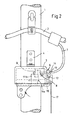
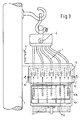
- the shorting cover 10 is for example in the Figures 2 and 3 shown.
- the short-circuiting lid is provided in the installed position on the inside of the contact poles 9 with a shorting bridge 11a, which is provided according to the number of contact poles 9, in theknownsbelspiel described five, with contact blades 11b (contact webs), which in the short-circuited position of the shorting cover 10 (FIG. FIG. 2 ) are in engagement with the contact poles 9, so that an all-pole short circuit of the overhead line 3 is effected.
- the short-circuiting bridge 11a is captively fastened to the short-circuiting cover 10.
- Both the cover 5 and the short-circuiting cover 10 are provided on one side with two bearing journals 12 which are each provided on one side of the connection housing 3 provided journal bearing 13 are mounted.
- the journal bearings are open in the installed position of the terminal housing 3 against the direction of gravity and provided with a slotted guide 14 for guiding the bearing pin 12 in the end position.
- the slide guide 14 allows, for example, in the in FIG. 1
- the cover 5 as well as the shorting cover 10 are pivoted about the hinge pin formed by the bearing pin 12 and journal bearing 13 in the closed position.
- the closed position is for example in FIG. 1 drawn with dashed lines.
- a locking or snap mechanism not shown, which is sufficiently stiff to the cover 5 or the shorting cover 10 in the closed position hold.
- a tongue 15 is provided in each case, which is provided on the outside thereof with an engagement hole 16 for an actuating rod.
- an opening of the cover 5 can be accomplished with distance to the contact poles 9 safely. It is essential that the production of a short circuit by pivoting the shorting cover 10 in the in FIG. 2 shown position with distance to the contact poles 9 can be made.
- the short-circuiting cover 10 is preferably designed in a signal color which is significantly different from the color of the cover 5 or of the connection housing 3.
- the shorting cover 10 is provided with a signal lug 17, which hangs down visibly, preferably in the colors white / red, and which is visible on both sides when manufactured short circuit.
Landscapes
- Physics & Mathematics (AREA)
- General Physics & Mathematics (AREA)
- Testing Of Short-Circuits, Discontinuities, Leakage, Or Incorrect Line Connections (AREA)
Applications Claiming Priority (1)
| Application Number | Priority Date | Filing Date | Title |
|---|---|---|---|
| DE201010006006 DE102010006006A1 (de) | 2010-01-27 | 2010-01-27 | Prüf- und Kurzschlusseinrichtung an isolierten Freileitungsnetzen |
Publications (2)
| Publication Number | Publication Date |
|---|---|
| EP2363718A2 true EP2363718A2 (fr) | 2011-09-07 |
| EP2363718A3 EP2363718A3 (fr) | 2014-12-03 |
Family
ID=44000700
Family Applications (1)
| Application Number | Title | Priority Date | Filing Date |
|---|---|---|---|
| EP11000454.6A Withdrawn EP2363718A3 (fr) | 2010-01-27 | 2011-01-21 | Dispositif de contrôle et de court-circuitage sur des réseaux de lignes aériennes isolés |
Country Status (2)
| Country | Link |
|---|---|
| EP (1) | EP2363718A3 (fr) |
| DE (1) | DE102010006006A1 (fr) |
Cited By (2)
| Publication number | Priority date | Publication date | Assignee | Title |
|---|---|---|---|---|
| CN105954548A (zh) * | 2016-07-13 | 2016-09-21 | 中国人民解放军91224部队 | 一种防干扰可拆卸电场传感器支撑装置 |
| CN115498576A (zh) * | 2022-09-21 | 2022-12-20 | 国网山东省电力公司五莲县供电公司 | 一种电力供电系统 |
Families Citing this family (3)
| Publication number | Priority date | Publication date | Assignee | Title |
|---|---|---|---|---|
| DE102013205236A1 (de) * | 2012-10-17 | 2014-04-17 | Siemens Aktiengesellschaft | Überwachungsvorrichtung und Verfahren zum Überwachen einer Restspannung |
| CN113314977B (zh) * | 2021-06-22 | 2025-02-07 | 扬中海潮电力设备有限公司 | 一种可诊断系统故障的高压开关柜 |
| CN114039319B (zh) * | 2021-12-08 | 2023-08-15 | 国网河南省电力公司经济技术研究院 | 一种gis式带保护远跳功能的高压电缆临时跳通装置 |
Family Cites Families (7)
| Publication number | Priority date | Publication date | Assignee | Title |
|---|---|---|---|---|
| AT184241B (de) * | 1953-12-23 | 1955-12-27 | Karl Ing Hoffmann | Trennschalteranordnung für Schaltanlagen |
| DE1076217B (de) * | 1959-04-24 | 1960-02-25 | Pfisterer Karl | Anschlussstueck fuer stationaeren Erdungsanschluss in Hochspannungsanlagen |
| DE1173557B (de) * | 1960-04-21 | 1964-07-09 | Alois Schiffmann Dipl Kfm | Erdungsvorrichtung fuer Mehrleiter-Hochspannungsanlagen |
| US3863145A (en) * | 1973-08-29 | 1975-01-28 | Mc Graw Edison Co | Electrical fault detecting tool with fuse assembly and power line clamp device |
| DE7530169U (de) * | 1975-09-24 | 1977-03-31 | Elsic Elektrische Sicherheitsausruestungen Und Betriebsmittel Gmbh, 4050 Moenchengladbach | Erdungsvorrichtung für elektrische Schalt- und Verteileranlagen |
| DE2619794C2 (de) * | 1976-05-05 | 1983-08-18 | Dipl.-Ing. H. Horstmann Gmbh, 5628 Heiligenhaus | Kurzschlußanzeiger für Freileitungen |
| DE3430409A1 (de) * | 1984-08-17 | 1986-02-27 | Siemens AG, 1000 Berlin und 8000 München | Geraet zur ueberpruefung der abschalteinrichtung eines hochspannungsnetzteiles |
-
2010
- 2010-01-27 DE DE201010006006 patent/DE102010006006A1/de active Pending
-
2011
- 2011-01-21 EP EP11000454.6A patent/EP2363718A3/fr not_active Withdrawn
Non-Patent Citations (1)
| Title |
|---|
| None |
Cited By (3)
| Publication number | Priority date | Publication date | Assignee | Title |
|---|---|---|---|---|
| CN105954548A (zh) * | 2016-07-13 | 2016-09-21 | 中国人民解放军91224部队 | 一种防干扰可拆卸电场传感器支撑装置 |
| CN105954548B (zh) * | 2016-07-13 | 2019-06-11 | 中国人民解放军91224部队 | 一种防干扰可拆卸电场传感器支撑装置 |
| CN115498576A (zh) * | 2022-09-21 | 2022-12-20 | 国网山东省电力公司五莲县供电公司 | 一种电力供电系统 |
Also Published As
| Publication number | Publication date |
|---|---|
| DE102010006006A1 (de) | 2011-07-28 |
| EP2363718A3 (fr) | 2014-12-03 |
Similar Documents
| Publication | Publication Date | Title |
|---|---|---|
| DE102010006006A1 (de) | Prüf- und Kurzschlusseinrichtung an isolierten Freileitungsnetzen | |
| EP1830437A2 (fr) | Contact électrique | |
| DE202007019217U1 (de) | Vorrichtung für die Wartung von Hochspannungs-Schalteinrichtungen unter Spannung | |
| DE102012214981A1 (de) | Redundante blitzableitvorrichtung für eine windturbine | |
| EP2928025B1 (fr) | Dispositif de raccordement, ensemble d'installation et installation électrique | |
| DE102017214408A1 (de) | Vorrichtung zur Bestimmung eines Isolationswiderstandes, Batteriemanagementsystem, Automobil, portable Messeinheit und Verfahren zur Isolationswiderstandsbestimmung. | |
| DE10053363B4 (de) | Struktur einer Leiterschutzvorrichtung zur Herausführung von Leitern | |
| EP0219640A2 (fr) | Appareil d'installation à couvercle rabattable | |
| DE2838528A1 (de) | Stromverteilungseinrichtung mit schnellanschluessen | |
| DE202019106942U1 (de) | Anti-Rattankletterungs-Vorrichtung für Mastkabel | |
| EP1198817B1 (fr) | Unite coupe-circuit et bascule de commutation avec affichage de controle | |
| DE102015203634B4 (de) | Stromzuführung für einen Tür- oder Fensterflügel | |
| CN208571154U (zh) | 一种快速装卸的短接线夹 | |
| DE102017203205A1 (de) | Kabelbrückenmodul zur flexiblen verknüpfung von verbindungsklemmen | |
| DE102019105383A1 (de) | Messadapter für ein Elektrofahrzeug | |
| DE19752646A1 (de) | Anordnung in Verbindung mit einer Stromabnahmevorrichtung eines Stromschienensystems | |
| DE102015001890B4 (de) | Notleuchte | |
| DE535380C (de) | Anordnung zu Strommessungen in der laufenden Kabelstrecke bei elektrischen Mehrleiterkabeln | |
| DE520236C (de) | Verfahren zum Pruefen von elektrischen Installationsanlagen und installierten Zaehlern | |
| DE69930870T3 (de) | An einer übertragungsleitung befestigten schlagableiter mit einer stabilisierenden vorrichtung | |
| DE2449326A1 (de) | Klemmanschlussvorrichtung zur kontaktierung zwischen einem elektrischen leiter und einem anschlusselement | |
| DE102018133424A1 (de) | Anwesenheitskontrolle PE-Stromabnehmer | |
| DE709045C (de) | Elektrisches Schaltgeraet, insbesondere Selbstschalter | |
| DE919958C (de) | Blitzsicherung fuer Hausinstallationen | |
| DE1665380B1 (de) | Stromabnahme klemme |
Legal Events
| Date | Code | Title | Description |
|---|---|---|---|
| PUAI | Public reference made under article 153(3) epc to a published international application that has entered the european phase |
Free format text: ORIGINAL CODE: 0009012 |
|
| AK | Designated contracting states |
Kind code of ref document: A2 Designated state(s): AL AT BE BG CH CY CZ DE DK EE ES FI FR GB GR HR HU IE IS IT LI LT LU LV MC MK MT NL NO PL PT RO RS SE SI SK SM TR |
|
| AX | Request for extension of the european patent |
Extension state: BA ME |
|
| PUAL | Search report despatched |
Free format text: ORIGINAL CODE: 0009013 |
|
| AK | Designated contracting states |
Kind code of ref document: A3 Designated state(s): AL AT BE BG CH CY CZ DE DK EE ES FI FR GB GR HR HU IE IS IT LI LT LU LV MC MK MT NL NO PL PT RO RS SE SI SK SM TR |
|
| AX | Request for extension of the european patent |
Extension state: BA ME |
|
| RIC1 | Information provided on ipc code assigned before grant |
Ipc: G01R 31/02 20060101ALI20141027BHEP Ipc: H02B 5/02 20060101ALI20141027BHEP Ipc: H02G 1/02 20060101ALI20141027BHEP Ipc: G01R 1/04 20060101AFI20141027BHEP Ipc: H02B 1/16 20060101ALI20141027BHEP Ipc: H02G 7/05 20060101ALI20141027BHEP |
|
| STAA | Information on the status of an ep patent application or granted ep patent |
Free format text: STATUS: THE APPLICATION IS DEEMED TO BE WITHDRAWN |
|
| 18D | Application deemed to be withdrawn |
Effective date: 20150604 |