EP2363728A1 - Appareil de radar cohérent à faisceau entrelacé et procédé de traitement - Google Patents
Appareil de radar cohérent à faisceau entrelacé et procédé de traitement Download PDFInfo
- Publication number
- EP2363728A1 EP2363728A1 EP11156293A EP11156293A EP2363728A1 EP 2363728 A1 EP2363728 A1 EP 2363728A1 EP 11156293 A EP11156293 A EP 11156293A EP 11156293 A EP11156293 A EP 11156293A EP 2363728 A1 EP2363728 A1 EP 2363728A1
- Authority
- EP
- European Patent Office
- Prior art keywords
- doppler
- range
- radar
- beams
- buffers
- Prior art date
- Legal status (The legal status is an assumption and is not a legal conclusion. Google has not performed a legal analysis and makes no representation as to the accuracy of the status listed.)
- Ceased
Links
Images
Classifications
-
- G—PHYSICS
- G01—MEASURING; TESTING
- G01S—RADIO DIRECTION-FINDING; RADIO NAVIGATION; DETERMINING DISTANCE OR VELOCITY BY USE OF RADIO WAVES; LOCATING OR PRESENCE-DETECTING BY USE OF THE REFLECTION OR RERADIATION OF RADIO WAVES; ANALOGOUS ARRANGEMENTS USING OTHER WAVES
- G01S13/00—Systems using the reflection or reradiation of radio waves, e.g. radar systems; Analogous systems using reflection or reradiation of waves whose nature or wavelength is irrelevant or unspecified
- G01S13/02—Systems using reflection of radio waves, e.g. primary radar systems; Analogous systems
- G01S13/06—Systems determining position data of a target
- G01S13/42—Simultaneous measurement of distance and other co-ordinates
- G01S13/426—Scanning radar, e.g. 3D radar
-
- G—PHYSICS
- G01—MEASURING; TESTING
- G01S—RADIO DIRECTION-FINDING; RADIO NAVIGATION; DETERMINING DISTANCE OR VELOCITY BY USE OF RADIO WAVES; LOCATING OR PRESENCE-DETECTING BY USE OF THE REFLECTION OR RERADIATION OF RADIO WAVES; ANALOGOUS ARRANGEMENTS USING OTHER WAVES
- G01S13/00—Systems using the reflection or reradiation of radio waves, e.g. radar systems; Analogous systems using reflection or reradiation of waves whose nature or wavelength is irrelevant or unspecified
- G01S13/02—Systems using reflection of radio waves, e.g. primary radar systems; Analogous systems
- G01S13/50—Systems of measurement based on relative movement of target
- G01S13/58—Velocity or trajectory determination systems; Sense-of-movement determination systems
- G01S13/581—Velocity or trajectory determination systems; Sense-of-movement determination systems using transmission of interrupted pulse modulated waves and based upon the Doppler effect resulting from movement of targets
- G01S13/582—Velocity or trajectory determination systems; Sense-of-movement determination systems using transmission of interrupted pulse modulated waves and based upon the Doppler effect resulting from movement of targets adapted for simultaneous range and velocity measurements
-
- G—PHYSICS
- G01—MEASURING; TESTING
- G01S—RADIO DIRECTION-FINDING; RADIO NAVIGATION; DETERMINING DISTANCE OR VELOCITY BY USE OF RADIO WAVES; LOCATING OR PRESENCE-DETECTING BY USE OF THE REFLECTION OR RERADIATION OF RADIO WAVES; ANALOGOUS ARRANGEMENTS USING OTHER WAVES
- G01S13/00—Systems using the reflection or reradiation of radio waves, e.g. radar systems; Analogous systems using reflection or reradiation of waves whose nature or wavelength is irrelevant or unspecified
- G01S13/02—Systems using reflection of radio waves, e.g. primary radar systems; Analogous systems
- G01S2013/0236—Special technical features
- G01S2013/0245—Radar with phased array antenna
- G01S2013/0254—Active array antenna
Definitions
- Embodiments of the invention generally pertain to electronically-steered pulse-Doppler radar systems and methods. More particularly, embodiments on the invention pertain to a method of radar energy management and Doppler processing. Embodiments are further directed to a method for artificially increasing the coherent integration time (Doppler resolution) for a given receive position without penalty to the overall radar timeline.
- Doppler resolution coherent integration time
- Doppler processing in radar systems is well known.
- a set number of multiple pulses are transmitted at a constant "pulse repetition interval" (PRI).
- the total number of pulses to be processed at a time multiplied by the PRI is typically referred to as the “coherent period of integration” (CPI).
- the radar processor stores received complex signals (Range samples) as a function of time (sometimes referred to as “fast time,” corresponding to samples in range of energy returned from a single pulse) from each successive individual pulse (sometimes referred to as “slow time,” with the value corresponding to pulse or pulse repetition interval (PRI) number within a given CPI).
- a Fourier transform is performed across the data points for all of the PRIs within a CPI. This calculation transforms phase change rate across the PRIs at a common range into Doppler. When performed for all range samples, the result is a two dimensional array of complex values that correspond to radar Range and Doppler.
- Doppler resolution is often described as the ability to separate two sources of response at two different Dopplers at the same range.
- Doppler resolution is a function of radar frequency and the CPI.
- Unambiguous Doppler corresponds to the breadth of range rate that the radar can measure a target unambiguously, i.e. without aliasing.
- the unambiguous Doppler is determined by the radar frequency and the radar "pulse repetition frequency" (PRF).
- PRF can be represented as the inverse of the PRI duration.
- the unambiguous Doppler divided by the number of PRIs within a CPI results in a value that approximates the Doppler resolution capability. For example, in the case that the frequency and CPI duration result in an unambiguous Doppler capability covering 0 meters per second (m/s) to 320 m/s, and the CPI contains 32 pulses, the resulting Doppler resolution can be approximated to be 10 m/s.
- An embodiment of the invention is directed to a method for Doppler processing.
- a non-limiting aspect of the invention is directed to a method for managing Doppler resolution for short duration CPIs in radar systems through an interleaved coherent beam pointing with a corresponding Doppler processing technique.
- Another non-limiting aspect of the invention is directed to a method for efficient energy management for radar systems, enabling the use of short CPI waveform sets that would otherwise be ineffective due to possessing a Doppler resolution not sufficient for target detection. This increases the time available for the use of long pulsewidths in conjunction with waveform sets tuned to maximize radar detection range.
- an embodiment of the invention is directed to a method for pulse-Doppler radar including the steps of providing a plurality of synchronized, coherent, pulsed transmit beams having substantially repeatable gain and phase pattern characteristics; electronically steering the plurality of transmit beams in a respective, sequential plurality of spatially diverse directions in a temporally-interleaved manner; sequentially collecting a respective plurality of receive beams in a respective plurality of time vs. range buffers; repeating the above steps for a desired number of pulse repetition intervals to achieve desired range-Doppler resolution characteristics; and determining a range-Doppler output at a selected, common receive position in each of the plurality of buffers.
- An embodiment of the invention is directed to an Electronically Scanned Array (ESA) radar system.
- the embodied system includes one or more processors that may be programmed to read and execute instructional commands and operational functions. These executable commands, instructions, and/or functions include one or more of the following: transmit a plurality of synchronized, coherent pulsed transmit beams having substantially repeatable gain and phase pattern characteristics; electronically steer the plurality of transmit beams in a respective, sequential plurality of spatially diverse directions in a temporally-interleaved manner; sequentially collect a respective plurality of receive beams in a respective plurality of time vs. range buffers; determine a range-Doppler output at a selected, common receive position in each of the plurality of buffers.
- non-transitory computer-readable media capable of storing said executable instructions and being read by the one or more processors.
- non-transitory computer readable media may comprise computer storage media and communication media.
- Computer storage media includes volatile and nonvolatile, removable and non-removable media implemented in any method or technology for storage of information such as computer-readable instructions, data structures, program modules, or other data.
- Computer storage media includes, but is not limited to, RAM, ROM, Erasable Programmable ROM (“EPROM”), Electrically Erasable Programmable ROM (“EEPROM”), flash memory or other solid state memory technology, CD-ROM, digital versatile disks (“DVD”), or other optical storage, magnetic cassettes, magnetic tape, magnetic disk storage or other magnetic storage devices, or any other medium which can be used to store the desired information and which can be accessed by the one or more processors.
- the embodiments and aspects of the present invention provide techniques for enhancing modern ESA radar system capabilities, as well as a novel ESA radar system.
- the apparatus and techniques take advantage of precision scan and time sampling technology, and utilizing new degrees of freedom in radar energy management by allowing for radar pulses in a CPI to be non-consecutive in angular direction, having the radar and processor perform multiple CPIs in parallel, and utilizing the associated increase in CPI (and associated decrease in unambiguous Doppler coverage) to create a performance advantage in Doppler resolution when compared to previous techniques.
- the embodied invention provides a way to artificially increase the coherent integration time for a given position without penalty to the energy timeline by transmitting in spatially diverse directions in an interleaved fashion.
- the embodied invention provides a way to reduce Doppler cell size for short-range waveforms without sacrificing timeline.
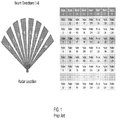
- Figure 1 shows the sample radar beam position and sequencing associated with the description in Example 1 for a traditional pulsed Doppler radar configuration
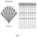
- Figure 2 shows the same radar beam positions and sequencing associated with the description in Example 1, according to a non-limiting, illustrative embodiment of the invention.
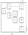
- FIG. 3 is a block diagram illustrating an ESA radar system according to an exemplary, illustrative embodiment of the invention.
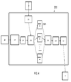
- Figure 4 is a block diagram showing the signal processor component of the radar system of Figure 3 .
- an arbitrary or pre-defined waveform is generated, amplified, and radiated from the radar antenna.
- the characteristics of the energy that is radiated from the antenna elements can be manipulated in amplitude and relative phase by modern antenna technologies that are well known.
- the transmitted energy can be directed in a desired spatial direction.
- energy received by the antenna can be manipulated in the same way.
- the direction that the phased array directs the energy in is typically referred to as the radar's beam position.
- the beam width of the radar system is a function of the frequency of the radar, the size of the antenna, and the amplitude settings of the individual antenna elements. (In some applications, element phasing is used to "spoil" the radar beamwidth, which widens the beamwidth but incurs radar signal loss.)
- Typical pulsed Doppler radar systems will direct the radar beam in a given direction, and will transmit and receive multiple pulses in that direction with precision timing. The radar will then direct the beam to the next desired position, and again will transmit / receive multiple pulses in that direction.
- the signal from the antenna may be down-converted to a lower frequency, and the resultant signal may be de-modulated or "pulse compressed" with techniques that are well known. Digitization of this signal may take place at any point in this process. While the descriptions associated with this invention assume digital data streams, comparable processes utilizing analog signals will yield the same advantages.
- typical pulsed Doppler radars will store digitized samples of the signal for what is sometimes referred to as "corner turn processing". For a single pulse, digital samples are measured at set time intervals, and correspond to range from the radar antenna. This process is repeated for multiple pulses, with the set of digital samples corresponding to ranges identical to that of the previous pulses.
- a set number of pulses are scheduled for processing.
- a Fourier transform calculation is performed on the samples of common range.
- the output of this calculation is a complex value for which the amplitude corresponds to the summation of signal received at a corresponding range rate, or Doppler.
- radars will typically utilize a Fast Fourier Transform (FFT) calculation for efficiency, which will generate the same number of phase rate coefficients in the calculation as there are pulses in the CPI.
- FFT Fast Fourier Transform
- the Doppler resolution is usually defined as the ability to separate targets and / or clutter that are at two different Dopplers and at a common range.
- the exact Doppler resolution of a radar system is dependent on many factors, but the fundamental properties that determine the Doppler resolution are the size of the CPI in time and the frequency of the radar.
- Unambiguous Doppler is defined as the limitation of the radar to measure the Doppler of a target without aliasing.
- Embodiments of the invention utilize additional degrees of freedom available on modern radars for the purpose of manipulation of Doppler resolution and unambiguous Doppler for target detection and/or radar timeline improvements.
- the methods described herein advantageously exploit the ability of modern radar systems to change the spatial direction of consecutive radar pulses and return to a previous spatial direction with precision repeatability, as well as modern computational capabilities for the simultaneous Doppler processing of multiple beams.
- Doppler Resolution c 2 ⁇ freq ⁇ CPI ⁇ #beams
- Unambiguous Doppler c 4 ⁇ freq ⁇ PRI ⁇ #beams where #beams is defined as the number of beam positions being simultaneously utilized.
- this technique will impact the Doppler resolution and the unambiguous Doppler associated with the target toward a reduced unambiguous Doppler, and a Doppler resolution that allows for the separation of targets or clutter that are closer in Doppler at a common range.
- Example 1 illustrates Doppler resolution improvements over conventional processing.
- a waveform PRI of 15 ⁇ sec (microseconds) is utilized, and 32 pulses integrated per CPI. This results in a CPI of 0.00048 seconds, and a total search time of 0.00384 seconds.
- a classical radar (refer to Figure 1 ) would direct the radar beam to position #1, pulse 32 times, then direct to position #2, pulse 32 times, and so on through position #8.
- the resulting characteristics are an unambiguous Doppler coverage of +/-1666.7 m/s, and an approximate Doppler resolution of 104.2 m/s.
- the instrumented range is approximately 2000 m, with range aliasing being well understood.
- the processing method would direct the radar beam to position #1, pulse one time, then direct to position #2, pulse 1 time, and so on for positions #'s 3-7, then direct to position #8, pulse 1 time, then redirect to position #1, pulse one time, etc., until each beam position had a total of 32 pulses.
- the resulting characteristics are an unambiguous Doppler coverage of +/- 208.3 m/s, and an approximate Doppler resolution of 13.0 m/s.
- the instrumented range remains unchanged at approximately 2000 m, and range aliasing is modified (with respect to transmit sidelobe power associated with the transmit of other beam positions, and with respect to well understood effects with an effective PRI that is eight times greater than the case of the classical implementation).
- a classical radar technique to achieve the Doppler resolution required would be to increase the CPI by a factor of 8, through either, or combination of, increasing the PRI length or the number of pulses. In either case, to achieve the same Doppler resolution, the radar timeline would require an increase by a factor of 8.
- an additional classical radar technique to achieve the Doppler resolution required would be to transmit a "spoiled" transmit beam that is wider than the given beamwidth "D" to place transmit energy on all 8 beam positions. This requires the assumption that all 8 beam positions are not too far apart and as such can be covered with a single spoiled transmit beam.
- the requirement to achieve the equivalent Doppler resolution as the instant embodied invention will require an additional 8 radar receiver channel sets, the capability to steer receive beam sets to 8 places simultaneously, and the equivalent processing of the instant embodied invention.
- spoiling a transmit beam to widen it will result in the loss of transmit energy.
- the CPIs of the 8 simultaneous receive channel sets would have to be lengthened, and hence require additional radar timeline as compared to the instant embodied invention.
- Example 2 illustrates radar timeline improvement in the presence of Doppler resolution requirements.
- the radar requires 128 pulses of 8 ⁇ s transmit pulses at a single beam location to achieve the minimum target detection range (unambiguous) of 9,300 m.
- the radar is limited to a 10% transmit duty cycle.
- the radar requirements include a need to provide continuous coverage from 400 m through 9300 m, with a Doppler resolution of less than 6 m/s.
- the required maximum target unambiguous Doppler is 300 m/s.
- the required search volume for this target requires 20 beam positions in disparate locations.
- a single beam position CPI will have to be approximately 0.0071 seconds in order to achieve the required Doppler resolution.
- the pulse width of at least one waveform set for each beam position will have to be 2 ⁇ s or less.
- Solution #1 (classical) -
- the requirements can be achieved utilizing a 2 ⁇ s pulse, a PRI of 65 ⁇ s, 512 pulses integrated, resulting in the desired requirements at an update rate of 0.67 seconds.
- Solution #2 (classical) - Requires the use of two waveform sets.
- Set #1 utilizes a 2 ⁇ s pulse, 56 ⁇ s PRI, and 128 pulses integrated, resulting in a target detection range of 6800 m.
- Set #2 uses an 8 ⁇ s pulse, 80 ⁇ s PRI, and 128 pulses integrated, resulted in the remaining target detection range required.
- the update rate for the entire range is 0.37 seconds, and all requirements are met.
- Solution #3 (according to an illustrative aspect of the instant invention) - Requires the use of two waveform sets.
- Set #1 utilizes a 1 ⁇ s pulse, 14 ⁇ s PRI, and 128 pulses integrated, and is interleaved between four beam positions at a time, resulting in a target detection range of 5700 m.
- the unambiguous Doppler and Doppler resolution are identical to that in Set #1 in Solution #2.
- Set #2 uses an 8 ⁇ s pulse, 80 ⁇ s PRI, and 128 pulses integrated, resulting in the remaining target detection range required.
- the update for the entire range is 0.24 seconds, and all requirements are met. Thus radar energy usage is more efficient for this scenario.
- FIG. 3 is a block diagram illustrating an ESA radar system 100 enabled to execute any and all of the following functions according to an embodiment of the invention: transmit a plurality of synchronized, coherent pulsed transmit beams having substantially repeatable gain and phase pattern characteristics; electronically steer the plurality of transmit beams in a respective, sequential plurality of spatially diverse directions in a temporally-interleaved manner; sequentially collect a respective plurality of receive beams in a respective plurality of time vs. range buffers (as shown within the signal processor 200 in Figure 4 ); determine a range-Doppler output at a selected, common receive position in each of the plurality of buffers.
- the non-limiting, illustrative radar system 100 shown in Figure 3 includes a radar beam scheduler 10, a waveform generator 12, an antenna controller 14, an antenna with integrated transmit amplifier 16, a transmit/receive switch or circulator 18, an analog to digital convertor , a signal processor 200, and a detection / user interface processor 22.
- the non-limiting, illustrative signal processor sub system 200 within radar system 100 includes an input 210 for the digitized receive measurement, an input 212 for the radar scheduler, a digital filter 214, a beam position data router 216, multiple buffers 218 n for data storage, a beam position selector 220, a corner-turn processor 222, and a detection and clutter processor 224.
- the radar system is capable of receiving and reading an executable instruction contained in a non-transitory machine-readable medium 25 that includes an executable instruction set comprising: transmit a plurality of synchronized, coherent transmit beams having substantially repeatable gain and phase pattern characteristics; steer the plurality of transmit beams in a respective, sequential plurality of spatially diverse directions in a temporally-interleaved manner; sequentially collect a respective plurality of receive beams in a respective plurality of time vs. range buffers; and determine a range-Doppler output at a selected, common receive position in each of the plurality of buffers.
Landscapes
- Engineering & Computer Science (AREA)
- Radar, Positioning & Navigation (AREA)
- Remote Sensing (AREA)
- Computer Networks & Wireless Communication (AREA)
- Physics & Mathematics (AREA)
- General Physics & Mathematics (AREA)
- Radar Systems Or Details Thereof (AREA)
Applications Claiming Priority (1)
| Application Number | Priority Date | Filing Date | Title |
|---|---|---|---|
| US12/715,480 US8259006B2 (en) | 2010-03-02 | 2010-03-02 | Interleaved beam coherent radar apparatus and processing method |
Publications (1)
| Publication Number | Publication Date |
|---|---|
| EP2363728A1 true EP2363728A1 (fr) | 2011-09-07 |
Family
ID=44080482
Family Applications (1)
| Application Number | Title | Priority Date | Filing Date |
|---|---|---|---|
| EP11156293A Ceased EP2363728A1 (fr) | 2010-03-02 | 2011-02-28 | Appareil de radar cohérent à faisceau entrelacé et procédé de traitement |
Country Status (3)
| Country | Link |
|---|---|
| US (1) | US8259006B2 (fr) |
| EP (1) | EP2363728A1 (fr) |
| IL (1) | IL211458A (fr) |
Cited By (3)
| Publication number | Priority date | Publication date | Assignee | Title |
|---|---|---|---|---|
| GB2500931A (en) * | 2012-04-05 | 2013-10-09 | Selex Galileo Ltd | Radar surveillance system |
| US20180074161A1 (en) * | 2015-04-09 | 2018-03-15 | Corvus Technologies Corp | Beacon and associated components for a ranging system |
| CN113655481A (zh) * | 2021-09-27 | 2021-11-16 | 水利部南京水利水文自动化研究所 | 一种InSAR变形监测精度提升和检验方法及系统 |
Families Citing this family (14)
| Publication number | Priority date | Publication date | Assignee | Title |
|---|---|---|---|---|
| US8872693B1 (en) | 2009-04-29 | 2014-10-28 | The United States of America as respresented by the Secretary of the Air Force | Radar signature database validation for automatic target recognition |
| US8350749B1 (en) * | 2009-04-29 | 2013-01-08 | The United States Of America As Represented By The Secretary Of The Air Force | Radar signature database validation for automatic target recognition |
| US8259006B2 (en) * | 2010-03-02 | 2012-09-04 | Src Inc. | Interleaved beam coherent radar apparatus and processing method |
| US12242929B2 (en) | 2013-12-11 | 2025-03-04 | United States Of America As Represented By The Secretary Of The Air Force | Fano-based information theoretic method (FBIT) for design and optimization of nonlinear systems |
| JP6331195B2 (ja) * | 2014-09-29 | 2018-05-30 | パナソニックIpマネジメント株式会社 | レーダ装置 |
| CN107015242B (zh) * | 2017-04-14 | 2019-11-19 | 北京佳讯飞鸿电气股份有限公司 | 一种探测方法及装置 |
| JP6828193B2 (ja) * | 2017-06-14 | 2021-02-10 | ビーエイイー・システムズ・インフォメーション・アンド・エレクトロニック・システムズ・インテグレイション・インコーポレーテッド | 合成開口を介した雨および運動の衛星トモグラフィ |
| US11555908B2 (en) | 2019-09-06 | 2023-01-17 | International Business Machines Corporation | Multi range radar system |
| US11108472B1 (en) * | 2019-10-08 | 2021-08-31 | Steven P. Leytus | Radar waveform generator configured for use in Wi-Fi systems testing |
| CN111751791B (zh) * | 2020-07-15 | 2022-08-19 | 四川九洲电器集团有限责任公司 | 多频连续波相干转发方法和装置 |
| CN112305528B (zh) * | 2020-10-26 | 2023-07-11 | 西安电子工程研究所 | 一种相控阵雷达重复周期优选方法 |
| CN115407328B (zh) * | 2021-05-26 | 2025-08-15 | 北京华航无线电测量研究所 | 一种利用交叠合成波束进行测速的多普勒雷达 |
| FR3143767B1 (fr) * | 2022-12-16 | 2024-12-13 | Thales Sa | Procédé de caractérisation de cible pour un dispositif de détection du type radar ou sonar multi-panneaux à balayage électronique |
| IT202400004042A1 (it) * | 2024-02-26 | 2025-08-26 | Virtualabs S R L | Metodo di progettazione/costruzione di un radar |
Citations (2)
| Publication number | Priority date | Publication date | Assignee | Title |
|---|---|---|---|---|
| US5128683A (en) * | 1991-04-16 | 1992-07-07 | General Electric Company | Radar system with active array antenna, elevation-responsive PRF control, and beam multiplex control |
| US20050253748A1 (en) * | 2003-10-10 | 2005-11-17 | Eli Brookner | Efficient technique for estimating elevation angle when using a broad beam for search in a radar |
Family Cites Families (14)
| Publication number | Priority date | Publication date | Assignee | Title |
|---|---|---|---|---|
| US3274594A (en) * | 1949-12-27 | 1966-09-20 | Robert M Page | Signal integrating radar system |
| US3858209A (en) * | 1962-07-27 | 1974-12-31 | Us Air Force | Radar moving target tracking system |
| US3408647A (en) * | 1964-08-18 | 1968-10-29 | North American Rockwell | Amti radar system |
| FR1515000A (fr) * | 1966-09-21 | 1968-03-01 | Labo Cent Telecommunicat | Perfectionnements aux radars doppler cohérents à impulsions |
| JPH03252581A (ja) | 1990-03-02 | 1991-11-11 | Mitsubishi Electric Corp | レーダ装置 |
| US5093649A (en) * | 1990-08-28 | 1992-03-03 | The Boeing Company | Bessel beam radar system using sequential spatial modulation |
| US5173706A (en) | 1991-04-16 | 1992-12-22 | General Electric Company | Radar processor with range sidelobe reduction following doppler filtering |
| US5262785A (en) * | 1992-04-30 | 1993-11-16 | General Electric Co. | Small target doppler detection system |
| US6952440B1 (en) | 2000-04-18 | 2005-10-04 | Sirf Technology, Inc. | Signal detector employing a Doppler phase correction system |
| US7382310B1 (en) | 2006-01-03 | 2008-06-03 | Gregory Hubert Piesinger | Method for independently setting range resolution, Doppler resolution, and processing gain of a pseudo-random coded radar system |
| US7646326B2 (en) * | 2006-04-28 | 2010-01-12 | The United States Of America As Represented By The Secretary Of The Air Force | Method and apparatus for simultaneous synthetic aperture radar and moving target indication |
| US8289203B2 (en) * | 2009-06-26 | 2012-10-16 | Src, Inc. | Radar architecture |
| US20110205120A1 (en) * | 2010-02-19 | 2011-08-25 | Src, Inc. | Monopulse Beamformer for Electronically Switched Antennas |
| US8259006B2 (en) * | 2010-03-02 | 2012-09-04 | Src Inc. | Interleaved beam coherent radar apparatus and processing method |
-
2010
- 2010-03-02 US US12/715,480 patent/US8259006B2/en active Active
-
2011
- 2011-02-28 IL IL211458A patent/IL211458A/en active IP Right Grant
- 2011-02-28 EP EP11156293A patent/EP2363728A1/fr not_active Ceased
Patent Citations (2)
| Publication number | Priority date | Publication date | Assignee | Title |
|---|---|---|---|---|
| US5128683A (en) * | 1991-04-16 | 1992-07-07 | General Electric Company | Radar system with active array antenna, elevation-responsive PRF control, and beam multiplex control |
| US20050253748A1 (en) * | 2003-10-10 | 2005-11-17 | Eli Brookner | Efficient technique for estimating elevation angle when using a broad beam for search in a radar |
Cited By (6)
| Publication number | Priority date | Publication date | Assignee | Title |
|---|---|---|---|---|
| GB2500931A (en) * | 2012-04-05 | 2013-10-09 | Selex Galileo Ltd | Radar surveillance system |
| US9651657B2 (en) | 2012-04-05 | 2017-05-16 | Leonardo Mw Ltd | Radar surveillance system |
| US20180074161A1 (en) * | 2015-04-09 | 2018-03-15 | Corvus Technologies Corp | Beacon and associated components for a ranging system |
| US10634764B2 (en) * | 2015-04-09 | 2020-04-28 | Corvus Technologies Corp | Beacon and associated components for a ranging system |
| CN113655481A (zh) * | 2021-09-27 | 2021-11-16 | 水利部南京水利水文自动化研究所 | 一种InSAR变形监测精度提升和检验方法及系统 |
| CN113655481B (zh) * | 2021-09-27 | 2023-11-24 | 水利部南京水利水文自动化研究所 | 一种InSAR变形监测精度提升和检验方法及系统 |
Also Published As
| Publication number | Publication date |
|---|---|
| US20110215962A1 (en) | 2011-09-08 |
| US8259006B2 (en) | 2012-09-04 |
| IL211458A (en) | 2015-09-24 |
| IL211458A0 (en) | 2011-06-30 |
Similar Documents
| Publication | Publication Date | Title |
|---|---|---|
| US8259006B2 (en) | Interleaved beam coherent radar apparatus and processing method | |
| US7567201B2 (en) | Vehicle-installation direction detection apparatus enabling accurate detection of target body directions irrespective of vehicle speed | |
| CN103210319B (zh) | 雷达系统 | |
| US20200191911A1 (en) | Fmcw radar with interfering signal suppression in the time domain | |
| US10054668B2 (en) | Probabilistic signal, detection, and track processing architecture and system | |
| US5128683A (en) | Radar system with active array antenna, elevation-responsive PRF control, and beam multiplex control | |
| US5748143A (en) | Adaptive post-doppler sequential beam processor | |
| US20080088499A1 (en) | Methods and apparatus for hyperview automotive radar | |
| US10928500B2 (en) | Distributed clutter motion suppression through multiple moving transmit phase centers | |
| US7737881B2 (en) | Signal processing system for pulse-doppler radar | |
| EP2182375A1 (fr) | Système, procédé et produit de programme informatique | |
| JPWO2007020704A1 (ja) | 目標物検出方法及び目標物検出装置 | |
| JP5656505B2 (ja) | レーダ装置 | |
| Shapir et al. | Doppler ambiguity resolving in TDMA automotive MIMO radar via digital multiple PRF | |
| EP0509842A2 (fr) | Processeur de radar avec supression des lobes latéraux à distance suivant un filtrage Doppler | |
| CN113093125A (zh) | 雷达的干扰源定位方法、系统及信号处理设备、存储介质 | |
| Park et al. | MPSK-MIMO FMCW radar-based indoor multipath recognition | |
| US12164056B2 (en) | Context based target detection | |
| KR102924637B1 (ko) | 타깃 위치 결정 장치 및 방법 | |
| JP4723880B2 (ja) | 電波誘導装置 | |
| RU2315332C1 (ru) | Радиолокационная станция | |
| Waqar et al. | Reconfigurable monopulse radar tracking processor | |
| RU2421749C1 (ru) | Устройство определения направления | |
| Sit et al. | Simple OFDM-based MIMO radar for real-time short-range area surveillance | |
| JP2747360B2 (ja) | 追尾レーダ装置 |
Legal Events
| Date | Code | Title | Description |
|---|---|---|---|
| PUAI | Public reference made under article 153(3) epc to a published international application that has entered the european phase |
Free format text: ORIGINAL CODE: 0009012 |
|
| AK | Designated contracting states |
Kind code of ref document: A1 Designated state(s): AL AT BE BG CH CY CZ DE DK EE ES FI FR GB GR HR HU IE IS IT LI LT LU LV MC MK MT NL NO PL PT RO RS SE SI SK SM TR |
|
| AX | Request for extension of the european patent |
Extension state: BA ME |
|
| 17P | Request for examination filed |
Effective date: 20120307 |
|
| 17Q | First examination report despatched |
Effective date: 20131002 |
|
| STAA | Information on the status of an ep patent application or granted ep patent |
Free format text: STATUS: THE APPLICATION HAS BEEN REFUSED |
|
| 18R | Application refused |
Effective date: 20160930 |