EP2363738A2 - Dispositif d'éclairage pour véhicule - Google Patents
Dispositif d'éclairage pour véhicule Download PDFInfo
- Publication number
- EP2363738A2 EP2363738A2 EP11001413A EP11001413A EP2363738A2 EP 2363738 A2 EP2363738 A2 EP 2363738A2 EP 11001413 A EP11001413 A EP 11001413A EP 11001413 A EP11001413 A EP 11001413A EP 2363738 A2 EP2363738 A2 EP 2363738A2
- Authority
- EP
- European Patent Office
- Prior art keywords
- light
- emitting
- section
- light guide
- translucent cover
- Prior art date
- Legal status (The legal status is an assumption and is not a legal conclusion. Google has not performed a legal analysis and makes no representation as to the accuracy of the status listed.)
- Withdrawn
Links
Images




Classifications
-
- G—PHYSICS
- G02—OPTICS
- G02B—OPTICAL ELEMENTS, SYSTEMS OR APPARATUS
- G02B6/00—Light guides; Structural details of arrangements comprising light guides and other optical elements, e.g. couplings
- G02B6/0001—Light guides; Structural details of arrangements comprising light guides and other optical elements, e.g. couplings specially adapted for lighting devices or systems
- G02B6/0011—Light guides; Structural details of arrangements comprising light guides and other optical elements, e.g. couplings specially adapted for lighting devices or systems the light guides being planar or of plate-like form
- G02B6/0013—Means for improving the coupling-in of light from the light source into the light guide
- G02B6/0015—Means for improving the coupling-in of light from the light source into the light guide provided on the surface of the light guide or in the bulk of it
- G02B6/0018—Redirecting means on the surface of the light guide
-
- F—MECHANICAL ENGINEERING; LIGHTING; HEATING; WEAPONS; BLASTING
- F21—LIGHTING
- F21S—NON-PORTABLE LIGHTING DEVICES; SYSTEMS THEREOF; VEHICLE LIGHTING DEVICES SPECIALLY ADAPTED FOR VEHICLE EXTERIORS
- F21S43/00—Signalling devices specially adapted for vehicle exteriors, e.g. brake lamps, direction indicator lights or reversing lights
- F21S43/10—Signalling devices specially adapted for vehicle exteriors, e.g. brake lamps, direction indicator lights or reversing lights characterised by the light source
- F21S43/13—Signalling devices specially adapted for vehicle exteriors, e.g. brake lamps, direction indicator lights or reversing lights characterised by the light source characterised by the type of light source
- F21S43/14—Light emitting diodes [LED]
-
- F—MECHANICAL ENGINEERING; LIGHTING; HEATING; WEAPONS; BLASTING
- F21—LIGHTING
- F21S—NON-PORTABLE LIGHTING DEVICES; SYSTEMS THEREOF; VEHICLE LIGHTING DEVICES SPECIALLY ADAPTED FOR VEHICLE EXTERIORS
- F21S43/00—Signalling devices specially adapted for vehicle exteriors, e.g. brake lamps, direction indicator lights or reversing lights
- F21S43/20—Signalling devices specially adapted for vehicle exteriors, e.g. brake lamps, direction indicator lights or reversing lights characterised by refractors, transparent cover plates, light guides or filters
- F21S43/235—Light guides
- F21S43/236—Light guides characterised by the shape of the light guide
- F21S43/241—Light guides characterised by the shape of the light guide of complex shape
-
- F—MECHANICAL ENGINEERING; LIGHTING; HEATING; WEAPONS; BLASTING
- F21—LIGHTING
- F21S—NON-PORTABLE LIGHTING DEVICES; SYSTEMS THEREOF; VEHICLE LIGHTING DEVICES SPECIALLY ADAPTED FOR VEHICLE EXTERIORS
- F21S43/00—Signalling devices specially adapted for vehicle exteriors, e.g. brake lamps, direction indicator lights or reversing lights
- F21S43/20—Signalling devices specially adapted for vehicle exteriors, e.g. brake lamps, direction indicator lights or reversing lights characterised by refractors, transparent cover plates, light guides or filters
- F21S43/235—Light guides
- F21S43/242—Light guides characterised by the emission area
- F21S43/245—Light guides characterised by the emission area emitting light from one or more of its major surfaces
-
- F—MECHANICAL ENGINEERING; LIGHTING; HEATING; WEAPONS; BLASTING
- F21—LIGHTING
- F21S—NON-PORTABLE LIGHTING DEVICES; SYSTEMS THEREOF; VEHICLE LIGHTING DEVICES SPECIALLY ADAPTED FOR VEHICLE EXTERIORS
- F21S43/00—Signalling devices specially adapted for vehicle exteriors, e.g. brake lamps, direction indicator lights or reversing lights
- F21S43/20—Signalling devices specially adapted for vehicle exteriors, e.g. brake lamps, direction indicator lights or reversing lights characterised by refractors, transparent cover plates, light guides or filters
- F21S43/235—Light guides
- F21S43/249—Light guides with two or more light sources being coupled into the light guide
-
- F—MECHANICAL ENGINEERING; LIGHTING; HEATING; WEAPONS; BLASTING
- F21—LIGHTING
- F21S—NON-PORTABLE LIGHTING DEVICES; SYSTEMS THEREOF; VEHICLE LIGHTING DEVICES SPECIALLY ADAPTED FOR VEHICLE EXTERIORS
- F21S43/00—Signalling devices specially adapted for vehicle exteriors, e.g. brake lamps, direction indicator lights or reversing lights
- F21S43/20—Signalling devices specially adapted for vehicle exteriors, e.g. brake lamps, direction indicator lights or reversing lights characterised by refractors, transparent cover plates, light guides or filters
- F21S43/27—Attachment thereof
-
- G—PHYSICS
- G02—OPTICS
- G02B—OPTICAL ELEMENTS, SYSTEMS OR APPARATUS
- G02B6/00—Light guides; Structural details of arrangements comprising light guides and other optical elements, e.g. couplings
- G02B6/0001—Light guides; Structural details of arrangements comprising light guides and other optical elements, e.g. couplings specially adapted for lighting devices or systems
- G02B6/0011—Light guides; Structural details of arrangements comprising light guides and other optical elements, e.g. couplings specially adapted for lighting devices or systems the light guides being planar or of plate-like form
- G02B6/0013—Means for improving the coupling-in of light from the light source into the light guide
- G02B6/0015—Means for improving the coupling-in of light from the light source into the light guide provided on the surface of the light guide or in the bulk of it
- G02B6/002—Means for improving the coupling-in of light from the light source into the light guide provided on the surface of the light guide or in the bulk of it by shaping at least a portion of the light guide, e.g. with collimating, focussing or diverging surfaces
-
- G—PHYSICS
- G02—OPTICS
- G02B—OPTICAL ELEMENTS, SYSTEMS OR APPARATUS
- G02B6/00—Light guides; Structural details of arrangements comprising light guides and other optical elements, e.g. couplings
- G02B6/0001—Light guides; Structural details of arrangements comprising light guides and other optical elements, e.g. couplings specially adapted for lighting devices or systems
- G02B6/0011—Light guides; Structural details of arrangements comprising light guides and other optical elements, e.g. couplings specially adapted for lighting devices or systems the light guides being planar or of plate-like form
- G02B6/0033—Means for improving the coupling-out of light from the light guide
- G02B6/0035—Means for improving the coupling-out of light from the light guide provided on the surface of the light guide or in the bulk of it
- G02B6/0038—Linear indentations or grooves, e.g. arc-shaped grooves or meandering grooves, extending over the full length or width of the light guide
-
- G—PHYSICS
- G02—OPTICS
- G02B—OPTICAL ELEMENTS, SYSTEMS OR APPARATUS
- G02B6/00—Light guides; Structural details of arrangements comprising light guides and other optical elements, e.g. couplings
- G02B6/0001—Light guides; Structural details of arrangements comprising light guides and other optical elements, e.g. couplings specially adapted for lighting devices or systems
- G02B6/0011—Light guides; Structural details of arrangements comprising light guides and other optical elements, e.g. couplings specially adapted for lighting devices or systems the light guides being planar or of plate-like form
- G02B6/0033—Means for improving the coupling-out of light from the light guide
- G02B6/0035—Means for improving the coupling-out of light from the light guide provided on the surface of the light guide or in the bulk of it
- G02B6/0045—Means for improving the coupling-out of light from the light guide provided on the surface of the light guide or in the bulk of it by shaping at least a portion of the light guide
- G02B6/0046—Tapered light guide, e.g. wedge-shaped light guide
-
- G—PHYSICS
- G02—OPTICS
- G02B—OPTICAL ELEMENTS, SYSTEMS OR APPARATUS
- G02B6/00—Light guides; Structural details of arrangements comprising light guides and other optical elements, e.g. couplings
- G02B6/0001—Light guides; Structural details of arrangements comprising light guides and other optical elements, e.g. couplings specially adapted for lighting devices or systems
- G02B6/0011—Light guides; Structural details of arrangements comprising light guides and other optical elements, e.g. couplings specially adapted for lighting devices or systems the light guides being planar or of plate-like form
- G02B6/0075—Arrangements of multiple light guides
- G02B6/0078—Side-by-side arrangements, e.g. for large area displays
Definitions
- the present invention relates to a lighting device for a vehicle.
- a lighting device for a vehicle having a configuration in which a light source is provided in a lamp house formed in the vehicle and a light guide is provided in front of the light source, wherein light from the light source is guided into the light guide to be branched so that the light is emitted from a plurality of emitting sections (for example, see JP 4,290,601 ).
- the light from the light source is made to be emitted from a plurality of emitting sections by using the light guide. Therefore, the light is emitted in a wide range from arbitrary positions regardless of the position of the light entering section.
- the emitting surfaces of the plurality of emitting sections are provided on the same surface. Therefore, when the translucent cover which covers the emitting sections is slanted with respect to the emitting surfaces of the emitting sections, the distances between each of the emitting sections and the translucent cover differ from each other. Therefore, when seen from the front through the translucent cover, the emitting sections are observed differently.
- the emitting sections close to the translucent cover can be observed clearly when seen from the front through the translucent cover.
- the emitting sections away from the translucent cover are difficult to be observed. This is not preferable in view of designing.
- the emitting sections are seen from the front in a state where the lighting device of the vehicle is lit, the light emitting surfaces of the emitting sections close to the translucent cover are vivid. However, the light emitting surfaces of the emitting sections away from the translucent cover are blurred. Thus, unevenness in light emitting occurs.
- An object of the present invention is to make the emitting sections be observed uniformly along the slanting direction of the translucent cover when the emitting sections are seen from the front through the translucent cover in the lighting device for a vehicle which includes the translucent cover that is slanted with respect to the emitting sections.
- a lighting device for a vehicle reflecting one aspect of the present invention includes a translucent cover which closes a lamp house of the vehicle, a light source which is provided in the lamp house and a light guide which is provided in front of the light source in the lamp house, the light guide including an emitting section having an emitting surface which faces forward and a light guide section which is formed integrally with the emitting section and which introduces light from the light source inside to guide the light to the emitting section, and the translucent cover has a slanted wall which faces the emitting section and is slanted with respect to a front direction, the emitting section is constituted of a plurality of emitting parts, the plurality of emitting parts are arranged parallelly along a slanting direction of the slanted wall via the light guide section, and two of the emitting parts which are adjacent to each other have a level difference between each other in a front-back direction so as to trace a slant of the slanted wall.
- FIG. 1 is a front view of a combination lamp 1 which is installed at the rear left side of a vehicle
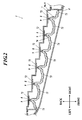
- FIG. 2 is a cross-sectional view when cut along the line II-II shown in FIG. 1
- FIG. 3 is a cross-sectional view when cut along the line III-III shown in FIG. 1 .
- the combination lamp is installed at each of rear left and rear right sides of a vehicle.
- the combination lamp for right side and the combination lamp for left side have structures which are line symmetry to each other, only the combination lamp 1 which is to be installed at the rear left side of a vehicle will be described in the following description and drawings and descriptions of the combination lamp which is to be installed at the rear right side of a vehicle will be omitted.
- the combination lamp 1 which is to be installed at the rear left side of a vehicle will be installed in the vehicle so that the front face of the combination lamp 1 faces backward direction of the vehicle. Therefore, in the following description, it is assumed that “front (front side)”, “back (back side)”, “right” and “left” mean “front (front side)”, “back (back side)”, “right” and “left” when the vehicle is seen from the back unless there is a specific notification.
- the combination lamp 1 of the embodiment includes a tail lamp 2 and a turn signal lamp 3 which are installed in a lamp house.
- the tail lamp 2 and the turn signal lamp 3 of the combination lamp 1 are covered with a translucent cover 4 which closes the opening of the lamp house.
- the translucent cover 4 is slanted so that the right part thereof projects more forward than the left part thereof as shown in FIG. 2 when seen planarly and so that the lower part thereof projects more forward than the upper part thereof as shown in FIG. 3 when seen from the right side, when the combination lamp 1 is installed in the vehicle.
- the tail lamp 2 is set so as to extend in a line form along three sides (upper side, right side and lower side) of the translucent cover 4 as shown in FIG. 1 when seen from the front.
- the turn signal lamp 3 is arranged at a position where three directions (up, right and left) are encircled by the tail lamp 2 as shown in FIG. 1 when seen from the front.
- the turn signal lamp 3 is formed in a shape similar to the outer shape of the translucent cover 4 when seen from the front.
- the turn signal lamp 3 includes a light emitting device 31 such as LED, a reflector 32, a transparent cover 33 and a diffusion plate 34.
- the turn signal lamp 3 has a configuration in which light from the light emitting device 31 is totally reflected by the reflector 32 and guided to the diffusion plate 34 through the transparent cover 33, and after the light is sufficiently diffused by the diffusion plate 34, the light is emitted outside through the translucent cover 4.
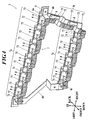
- FIG. 4 is a front schematic view of the tail lamp 2 and FIG. 5 is a back schematic view of the light guide.
- the tail lamp 2 includes a plurality of base plates 8, light emitting devices (light sources) 9 each of which is attached to each of the base plates 8, a light guide 7 which introduces the light from each of the light emitting devices 9 inside thereof and emits the light toward front direction and a supporting member 6 which supports the base plates 8, the light emitting devices 9 and the light guide 7.
- the light guide 7 is constituted of an upper light guide 7a, a right light guide 7b and a lower light guide 7c.
- Each of the upper light guide 7a, the right light guide 7b and the lower light guide 7c includes a plurality of emitting sections (emitting parts) 73.
- Each of the emitting sections 73 is formed in a rectangular shape when seen from the front.
- the upper light guide 7a is set so as to extend in a line form along the upper side of the translucent cover 4 when seen from the front.
- the upper light guide 7a is formed in stairs so as to trace the slant of a part of the translucent cover 4 that faces the upper light guide 7a. That is, with respect to any two emitting sections 73 which are adjacent to each other side by side, the emitting section on the right side is positioned more forward than the emitting section on the left side.
- the right light guide 7b is set so as to extend in a line form along the right side of the translucent cover 4 when seen form the front.
- the right light guide 7b is formed in stairs so as to trace the slant of the translucent cover 4 that faces the right light guide 7b. That is, with respect to any two emitting sections 73 which are arranged one above the other, the lower emitting section is positioned more forward than the upper emitting section.
- the lower light guide 7c is set so as to extend in a line form along the lower side of the translucent cover 4 when seen from the front.
- the lower light guide 7c is formed in stairs so as to trace the slant of a part of the translucent cover 4 that faces the lower light guide 7c. That is, with respect to any two emitting sections 73 which are adjacent to each other side by side, the emitting section on the right side is positioned more forward than the emitting section on the left side.
- Each of the upper light guide 7a, the right light guide 7b and the lower light guide 7c includes light guide sections 72 which introduce the light from the light emitting devices 9 inside thereof to guide the light to the emitting sections 73 in addition to the plurality of emitting sections 73.
- the light guide sections 72 are formed integrally with the emitting sections 73, wherein one light guide section 72 being arranged between two emitting sections 73 which are adjacent to each other.
- Each light guide section 72 arranged in between two emitting sections 73 projects to back side of the emitting sections 73, and the back end of each light guide section 72 becomes narrower towards the back part and forms a truncated cone section 72a in which the light axis Ax (defined later) is the rotation symmetry axis.
- each of the light guide sections 72 includes a light entering section 721 from which the light from the light emitting device 9 enters into the light guide, a branching section 722 which branches the light entered from the light entering section 721 in two and a reflecting section 723 which reflects the light which is branched in two by the branching section 722 separately toward the emitting sections 73 which are adjacent to each other.
- the light entering section 721 is structured to form the truncated cone section 72a as shown in FIG. 5 .
- a cone hole 72b which opens toward back direction is formed.
- the cone hole 72b is formed in a cone shape in which the light axis Ax (defined later) is the rotation symmetry axis.
- a convex surface (aspheric surface) 72c which bulges out toward back direction and which has the rotation symmetry axis is formed.
- the light axis Ax is defined as the rotation symmetry axis of the convex surface 72c.
- FIG. 6 one light source (light emitting device 9) and the light guide module which emits light by the one light source are shown.
- the light guide module 70 includes the first emitting part 731, the second emitting part 732 and a light guide section 720 which guides the light from the light emitting device 9 to the first emitting part 731 and the second emitting part 732.
- the first emitting part 731 constitutes half of either one of the two emitting sections 73 in the light guide 7 which are adjacent to each other and the second emitting part 732 constitutes half of the other of the two emitting sections 73.
- the light guide section 720 of the light guide module 70 corresponds to the light guide section 72 of the light guide 7.
- each of the upper light guide 7a, the right light guide 7b and the lower light guide 7c is constituted.
- the light guide sections 72 and the emitting sections 73 in the light guide 7 will be described in detail by using the light guide module 70 with reference to FIG. 7 .
- the convex surface 72c which is formed in the light entering section 721 structures the first light entering surface 721a. Further, the wall surface of the cone hole 72b structures the second light entering surface 721b and the wall surface of the truncated cone section 72a structures the reflecting surface 721c. Furthermore, the light emitting device 9 is set in a region which is enclosed by the first light entering surface 721a and the second light entering surface 721b, the light emitting device 9 facing front so as to match with the focus position of the first light entering surface 721a.
- the light entering section 721 functions to make the light from the light emitting device 9 which enters the first light entering surface 721a be the light which is parallel to the light axis Ax that emits toward the light axis Ax direction and makes the light which enters the second light entering surface 721b be the light parallel to the light axis Ax that emits toward the light axis Ax direction by totally reflecting the light by the reflecting surface 721c.
- the branching section 722 is constituted of a bifurcated section, and the light from the first light entering surface 721a and the reflecting surface 721c is branched into two at the branching part of the bifurcated section.
- the reflecting section 723 is constituted of the first reflecting surface 723a and the second reflecting surface 723b which reflect the light which is branched by the branching section 722 separately toward the first emitting part 731 and the second emitting part 732, respectively.
- the first reflecting surface 723a and the second reflecting surface 723b are formed to have level difference therebetween in the light axis Ax direction so as to correspond to the level difference between the first emitting part 731 and the second emitting part 732.
- the first reflecting surface 723a and the second reflecting surface 723b are slanted so as to have an angle of 45 degree with respect to the light axis Ax.
- the first reflecting surface 723a and the second reflecting surface 723b function to reflect the light which is branched in two by the branching section 722 separately to guide the lights to the first emitting part 731 and the second emitting part 732.
- first reflecting surface 723a and the second reflecting surface 723b may be parabolic surfaces and not plane surfaces.
- a plurality of reflecting surfaces 731a which reflect the light from the first reflecting surface 723a in the forward direction are provided at the back of the first emitting part 731.
- the back surface of the first emitting part 731 is formed in stairs.
- the stair treads 731b of the back surface of the first emitting part 731 which is formed in stairs are surfaces which are orthogonal to the light axis Ax, and the stair treads are made to be positioned more in front gradually as the stair treads be away from the light axis Ax.
- Each of the reflecting surfaces 731a is arranged between two stair treads 731b which are adjacent to each other and each of the reflecting surfaces 731a is formed so as to be parallel to the first reflecting surface 723a.
- the front surface of the first emitting part 731 is a large cylindrical surface which bulges toward front having a bus bar in a direction orthogonal to the light axis Ax.
- a plurality of cylindrical surfaces 731c which are smaller than the cylindrical surface which is the front surface of the first emitting part 731 are provided parallelly in a direction going away from the light axis Ax.
- the first emitting part 731 functions to diffuse and emit the light.
- a plurality of reflecting surfaces 731a are formed, and one reflecting surface which is parallel to the first reflecting surface 723a may be formed.
- a plurality of small lens surfaces for diffusing the light may be formed in a lattice form instead of the plurality of cylindrical surfaces 731c.
- a plurality of reflecting surfaces 732a which reflect the light from the first reflecting surface 723b in the forward direction are provided at the back of the second emitting part 732.
- the back surface of the second emitting part 732 is formed in stairs.
- the stair treads 732b of the back surface of the second emitting part 732 which is formed in stairs are surfaces which are orthogonal to the light axis Ax, and the stair treads are made to be positioned more in front gradually as the stair treads be away from the light axis Ax.
- Each of the reflecting surfaces 732a is arranged between two stair treads 732b which are adjacent to each other, and each of the reflecting surfaces 732a is formed in parallel with the first reflecting surface 723b.
- the front surface of the second emitting part 732 is a large cylindrical surface which bulges toward front having a bus bar in a direction orthogonal to the light axis Ax, for example. Further, on the front surface of the second emitting part 732, a plurality of cylindrical surfaces 732c which are smaller than the cylindrical surface which is the front surface of the second emitting part 732 are provided parallelly in a direction going away from the light axis Ax.
- the second emitting part 732 functions to diffuse and emit the light.
- a plurality of reflecting surfaces 732a are formed, and one reflecting surface which is parallel to the second reflecting surface 723b may be formed.
- a plurality of small lens surfaces (prism surfaces) for diffusing the light may be formed in a lattice form instead of the plurality of cylindrical surfaces 732c.
- the supporting member 6 When seen from the front, the supporting member 6 is constituted of an upper supporting plate 6a, a right supporting plate 6b and a lower supporting plate 6c which are respectively set so as to extend along the three sides (upper side, right side and lower side) of the translucent cover 4. Further, an enforcing plate 6d is bridged between the left end of the upper supporting plate 6a and the left end of the lower supporting plate 6c.
- the upper supporting plate 6a is for supporting the upper light guide 7a.
- the upper supporting plate 6a When seen from the front, the upper supporting plate 6a is set so as to extend in a line form along the upper side of the translucent cover 4 similarly to the upper light guide 7a.
- the upper supporting plate 6a is bent to form stairs similarly as in the upper light guide 7a. That is, the upper supporting plate 6a has a plurality of stair treads, and with respect to any two stair treads which are adjacent to each other side by side, the stair tread on the right side is positioned more forward than the stair tread on the left side.
- the base plate 8 and the light emitting device 9 are attached at each of the stair treads of the upper supporting plate 6a, and the upper light guide 7a is attached to the upper supporting plate 6a so that each of the light guide sections 72 positions in front of each of the light emitting devices 9.
- the right supporting plate 6b is for supporting the right light guide 7b.
- the right supporting plate 6b When seen from the front, the right supporting plate 6b is set so as to extend in a line form along the right side of the translucent cover 4 similarly to the right light guide 7b. Further, the right supporting plate 6b is bent to form stairs similarly as in the right light guide 7b. That is, the right supporting plate 6b has a plurality of stair treads, and with respect to any two stair treads which are arranged one above the other, the lower stair tread is positioned more forward than the upper stair tread.
- the base plate 8 and the light emitting device 9 are attached at each of the stair treads of the right supporting plate 6b, and the right light guide 7b is attached to the right supporting plate 6b so that each of the light guide sections 72 positions in front of each of the light emitting devices 9.
- the lower supporting plate 6c is for supporting the lower light guide 7c.
- the lower supporting plate 6c When seen from the front, the lower supporting plate 6c is set so as to extend in a line form along the lower side of the translucent cover 4 similarly to the lower light guide 7c. Further, the lower supporting plate 6c is bent to form stairs similarly as in the lower light guide 7c. That is, the lower supporting plate 6c has a plurality of stair treads, and with respect to any two stair treads which are adjacent to each other side by side, the stair tread on the right side is positioned more forward than the stair tread on the left side.
- the base plate 8 and the light emitting device 9 are attached at each of the stair treads of the lower supporting plate 6c, and the lower light guide 7c is attached to the lower supporting plate 6c so that each of the light guide sections 72 positions in front of each of the light emitting devices 9.
- the emitting section of the light guide 7 is constituted of a plurality of emitting sections (emitting parts) 73 having level differences so as to trace the slant in the slanting direction of the slanted wall of the translucent cover 4. Therefore, for example, in a state where the lighting device of the vehicle is not lit, the distances between the slanted wall of the translucent cover 4 and the emitting sections 73 are equal to each other. Therefore, the emitting sections 73 can be visually confirmed uniformly when seen from the front through the translucent cover 4. Further, in a state where the lighting device for the vehicle is lit, the degree of light emission of the light emitting surfaces of the emitting sections 73 are uniformly vivid when seen from the front.
- FIG. 8 is a schematic view of the light guide module according to the second embodiment.
- the second embodiment has a structure similar to that of the light guide 7 of the first embodiment by connecting the light guide modules 70A of FIG. 8 integrally in a line form instead of the light guide modules 70 of the first embodiment.
- the diagram of the entire light guide which is formed by connecting the light guide modules 70A is not shown.
- the light guide module 70A of the second embodiment is different from the light guide module 70 of the first embodiment in that the sizes of the first emitting part 731 and the second emitting part 732 are different and the light amount to be introduced in the first emitting part 731 and the light amount to be introduced in the second emitting part 732 are different. That is, in the light guide module 70A, the second emitting part 732 is larger than the first emitting part 731 and the light amount to be introduced in the second emitting part 732 is greater than the light amount to be introduced in the first emitting part 731.
- the advantages similar to that of the first embodiment can be obtained, and further, flexibility in designing of a lighting device for a vehicle can be enhanced.
- FIG. 9 is a schematic view of the light guide module according to the third embodiment.
- the third embodiment has a structure similar to that of the light guide 7 of the first embodiment by connecting the light guide modules 70B of FIG. 9 integrally in a line form instead of the light guide modules 70 of the first embodiment.
- the diagram of the entire light guide which is formed by connecting the light guide modules 70B is not shown.
- the light guide module 70B of the third embodiment differs from the light guide module 70 of the first embodiment in that the emitting section 79 is formed at the branching part of the bifurcated section which structures the branching section 722.
- the emitting section 79 is provided on the light axis Ax, and the emitting section 79 faces the same direction as the first emitting part 731 and the second emitting part 732 and the front surface thereof is formed in a convex surface shape.
- the front surface of the emitting section 79 may be formed in a concave surface shape or a plane surface shape.
- light can also be emitted from between the first emitting part 731 and the second emitting part 732. Therefore, dark portion in between the first emitting part 731 and the second emitting part 732 can be reduced.
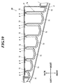
- FIG. 10 is a horizontal sectional view of a tail lamp 2B according to the fourth embodiment.
- the supporting member 6 of the tail lamp 2B is planarly formed so as to be orthogonal to the light axis Ax of the upper light guide 7a.
- the base plates 8 and the light emitting devices 9 are arranged on the front surface of the supporting member 6 by having a constant space therebetween.
- the light guide sections 72 become longer as the light guide sections 72 approach the right side.
- the right light guide 7b and the lower light guide 7c have the structure similar to the structure of the upper light guide 7a.
- the supporting member 6 is planarly formed, the supporting member 6 can be easily installed in the lamp house and can be easily replaced with an existing tail lamp.
- the present invention is applied to the tail lamp 2 of the combination lamp 1.
- the present invention can be applied to the turn signal lamp 3, a stop lamp (not shown) and a backup lamp (not shown).
- the present invention may be applied to a high mountain stop lamp, a front turn lamp, a side turn lamp and the like other than the turn signal lamp 3, the stop lamp and the backup lamp.
- the light emitting devices 9 such as LED are used as the light sources.
- inorganic electroluminescent elements, organic electroluminescent elements or other semiconductor light emitting elements may be used as the light emitting devices.
- bulbs light bulb may be used instead of the light emitting devices 9 as the light sources.
- a lighting device for a vehicle includes a translucent cover which closes a lamp house of the vehicle, a light source which is provided in the lamp house and a light guide which is provided in front of the light source in the lamp house, the light guide including an emitting section having an emitting surface which faces forward and a light guide section which is formed integrally with the emitting section and which introduces light from the light source inside to guide the light to the emitting section, and the translucent cover has a slanted wall which faces the emitting section and is slanted with respect to a front direction, the emitting section is constituted of a plurality of emitting parts, the plurality of emitting parts are arranged parallelly along a slanting direction of the slanted wall via the light guide section, and two of the emitting parts which are adjacent to each other have a level difference between each other in a front-back direction so as to trace a slant of the slanted wall.
- the light guide section includes a light entering section from which the light from the light source enters, a branching section which branches the light entered from the light entering section in two, and two reflecting surfaces which reflects the light which is branched in two by the branching section separately to guide the light to the two of the emitting parts.
- the light guide section includes another emitting section, which emits the light entered from the light entering section without making the light go through the two reflecting surfaces, in between the two reflecting surfaces.
- the emitting section of the light guide is constituted of a plurality of emitting parts having level difference so as to trace the slant in the slanting direction of the slanted wall of the translucent cover. Therefore, for example, in a state where the lighting device of the vehicle is not lit, the distances between the translucent cover and the emitting parts are equal to each other. Therefore, when seen from the front through the translucent cover, the emitting sections can be visually confirmed uniformly. Further, in a state where the lighting device of the vehicle is lit, the degree of light emission of the light emitting surfaces of the emitting sections are uniformly vivid when seen from the front.
Landscapes
- Engineering & Computer Science (AREA)
- General Engineering & Computer Science (AREA)
- Physics & Mathematics (AREA)
- Optics & Photonics (AREA)
- General Physics & Mathematics (AREA)
- Microelectronics & Electronic Packaging (AREA)
- Non-Portable Lighting Devices Or Systems Thereof (AREA)
Applications Claiming Priority (1)
| Application Number | Priority Date | Filing Date | Title |
|---|---|---|---|
| JP2010038246A JP5553643B2 (ja) | 2010-02-24 | 2010-02-24 | 車両用灯具 |
Publications (2)
| Publication Number | Publication Date |
|---|---|
| EP2363738A2 true EP2363738A2 (fr) | 2011-09-07 |
| EP2363738A3 EP2363738A3 (fr) | 2016-04-13 |
Family
ID=44022056
Family Applications (1)
| Application Number | Title | Priority Date | Filing Date |
|---|---|---|---|
| EP11001413.1A Withdrawn EP2363738A3 (fr) | 2010-02-24 | 2011-02-21 | Dispositif d'éclairage pour véhicule |
Country Status (2)
| Country | Link |
|---|---|
| EP (1) | EP2363738A3 (fr) |
| JP (1) | JP5553643B2 (fr) |
Cited By (12)
| Publication number | Priority date | Publication date | Assignee | Title |
|---|---|---|---|---|
| FR2995977A1 (fr) * | 2012-09-26 | 2014-03-28 | Valeo Vision | Guide de lumiere pour un dispositif d'eclairage et/ou de signalisation de vehicule automobile |
| WO2014074842A1 (fr) * | 2012-11-08 | 2014-05-15 | Fraen Corporation | Optique de mélange de couleur multi-del/multi-puce |
| CN103851542A (zh) * | 2012-11-29 | 2014-06-11 | 法雷奥照明公司 | 用于光学装置、特别是用于照明和/或信号指示的光导 |
| WO2016008897A1 (fr) * | 2014-07-15 | 2016-01-21 | Koninklijke Philips N.V. | Module d'éclairage de véhicule |
| FR3044778A1 (fr) * | 2015-12-07 | 2017-06-09 | Valeo Vision | Element optique transparent avec facettes de renvoi pour duplication d'image |
| US9784425B2 (en) | 2015-01-07 | 2017-10-10 | Varroc Lighting Systems, s.r.o. | Signal lamp |
| US9890920B2 (en) | 2014-09-19 | 2018-02-13 | Koito Manufacturing Co., Ltd. | Vehicular lamp |
| WO2018162037A1 (fr) * | 2017-03-07 | 2018-09-13 | HELLA GmbH & Co. KGaA | Dispositif d'éclairage pour véhicules |
| CN108626679A (zh) * | 2018-05-22 | 2018-10-09 | 常州星宇车灯股份有限公司 | 一种基于光导的用于机动车辆的光源组件 |
| WO2019015829A1 (fr) * | 2017-07-21 | 2019-01-24 | Weidplas Gmbh | Composant pour un véhicule |
| EP3486558B1 (fr) * | 2017-11-20 | 2022-09-07 | Foshan Ichikoh Valeo Auto Lighting Systems Co., Ltd. | Ensemble d'émission de lumière, appareil d'éclairage et véhicule |
| US20250146641A1 (en) * | 2022-02-21 | 2025-05-08 | Stanley Electric Co., Ltd. | Lighting tool for vehicle and vehicle rearward illumination system |
Families Citing this family (9)
| Publication number | Priority date | Publication date | Assignee | Title |
|---|---|---|---|---|
| JP5677122B2 (ja) * | 2011-02-15 | 2015-02-25 | スタンレー電気株式会社 | 車両用灯具 |
| JP2013152828A (ja) * | 2012-01-24 | 2013-08-08 | Stanley Electric Co Ltd | 車両用灯具 |
| KR102588792B1 (ko) * | 2016-02-15 | 2023-10-18 | 엘지이노텍 주식회사 | 램프 및 이를 구비하는 차량 |
| TWM535812U (zh) * | 2016-08-29 | 2017-01-21 | Chun Kuang Optics Corp | 光學透鏡組合及具有該光學透鏡組合的照明裝置 |
| US11422367B2 (en) * | 2017-06-16 | 2022-08-23 | Maxell, Ltd. | Light source apparatus and head up display apparatus |
| JP6901354B2 (ja) * | 2017-09-11 | 2021-07-14 | スタンレー電気株式会社 | 車両用灯具 |
| JP7023779B2 (ja) * | 2018-04-17 | 2022-02-22 | スタンレー電気株式会社 | 車両用灯具 |
| JP2022147959A (ja) * | 2021-03-24 | 2022-10-06 | スタンレー電気株式会社 | 車両用灯具 |
| JPWO2024195655A1 (fr) * | 2023-03-17 | 2024-09-26 |
Citations (1)
| Publication number | Priority date | Publication date | Assignee | Title |
|---|---|---|---|---|
| JP4290601B2 (ja) | 2004-05-17 | 2009-07-08 | 株式会社小糸製作所 | 車両用灯具ユニットおよび車両用灯具 |
Family Cites Families (6)
| Publication number | Priority date | Publication date | Assignee | Title |
|---|---|---|---|---|
| JP2005158362A (ja) * | 2003-11-21 | 2005-06-16 | Stanley Electric Co Ltd | 車両用灯具 |
| JP4497348B2 (ja) * | 2004-01-13 | 2010-07-07 | 株式会社小糸製作所 | 車両用灯具 |
| JP4290607B2 (ja) * | 2004-06-04 | 2009-07-08 | 株式会社小糸製作所 | 車両用灯具 |
| JP2006059541A (ja) * | 2004-08-17 | 2006-03-02 | Ichikoh Ind Ltd | 導光体及びそれを備えたled光源ユニット |
| JP4556140B2 (ja) * | 2006-12-07 | 2010-10-06 | 市光工業株式会社 | 車両用灯具 |
| JP2008166072A (ja) * | 2006-12-27 | 2008-07-17 | Ichikoh Ind Ltd | 導光体および車両用灯具 |
-
2010
- 2010-02-24 JP JP2010038246A patent/JP5553643B2/ja not_active Expired - Fee Related
-
2011
- 2011-02-21 EP EP11001413.1A patent/EP2363738A3/fr not_active Withdrawn
Patent Citations (1)
| Publication number | Priority date | Publication date | Assignee | Title |
|---|---|---|---|---|
| JP4290601B2 (ja) | 2004-05-17 | 2009-07-08 | 株式会社小糸製作所 | 車両用灯具ユニットおよび車両用灯具 |
Cited By (29)
| Publication number | Priority date | Publication date | Assignee | Title |
|---|---|---|---|---|
| WO2014049082A1 (fr) * | 2012-09-26 | 2014-04-03 | Valeo Vision | Guide de lumière pour un dispositif d'éclairage et/ou de signalisation de véhicule automobile |
| CN104822983A (zh) * | 2012-09-26 | 2015-08-05 | 法雷奥照明公司 | 用于汽车车辆的照明和/或信号通知设备的光导 |
| FR2995977A1 (fr) * | 2012-09-26 | 2014-03-28 | Valeo Vision | Guide de lumiere pour un dispositif d'eclairage et/ou de signalisation de vehicule automobile |
| US10012359B2 (en) | 2012-09-26 | 2018-07-03 | Valeo Vision | Light guide for a lighting and/or signaling device of an automobile vehicle |
| WO2014074842A1 (fr) * | 2012-11-08 | 2014-05-15 | Fraen Corporation | Optique de mélange de couleur multi-del/multi-puce |
| US10429565B2 (en) | 2012-11-08 | 2019-10-01 | Fraen Corporation | Multi-LED/multi-chip color mixing optics |
| US9746596B2 (en) | 2012-11-08 | 2017-08-29 | Fraen Corporation | Multi-LED/multi-chip color mixing optics |
| CN103851542B (zh) * | 2012-11-29 | 2018-10-16 | 法雷奥照明公司 | 用于光学装置、特别是用于照明和/或信号指示的光导 |
| CN103851542A (zh) * | 2012-11-29 | 2014-06-11 | 法雷奥照明公司 | 用于光学装置、特别是用于照明和/或信号指示的光导 |
| WO2016008897A1 (fr) * | 2014-07-15 | 2016-01-21 | Koninklijke Philips N.V. | Module d'éclairage de véhicule |
| US10386032B2 (en) | 2014-07-15 | 2019-08-20 | Koninklijke Philips N.V. | Vehicle lighting module |
| US9890920B2 (en) | 2014-09-19 | 2018-02-13 | Koito Manufacturing Co., Ltd. | Vehicular lamp |
| DE102016100207B4 (de) | 2015-01-07 | 2020-08-06 | Varroc Lighting Systems, s.r.o. | Signalleuchte |
| US9784425B2 (en) | 2015-01-07 | 2017-10-10 | Varroc Lighting Systems, s.r.o. | Signal lamp |
| FR3044778A1 (fr) * | 2015-12-07 | 2017-06-09 | Valeo Vision | Element optique transparent avec facettes de renvoi pour duplication d'image |
| EP3179157A1 (fr) * | 2015-12-07 | 2017-06-14 | Valeo Vision | Element optique transparent avec facettes de renvoi pour duplication d'image |
| CN110382949B (zh) * | 2017-03-07 | 2021-10-26 | 黑拉有限责任两合公司 | 用于交通工具的照明装置 |
| WO2018162037A1 (fr) * | 2017-03-07 | 2018-09-13 | HELLA GmbH & Co. KGaA | Dispositif d'éclairage pour véhicules |
| CN110382949A (zh) * | 2017-03-07 | 2019-10-25 | 黑拉有限责任两合公司 | 用于交通工具的照明装置 |
| US20200012035A1 (en) * | 2017-03-07 | 2020-01-09 | HELLA GmbH & Co. KGaA | Lighting device for vehicles |
| US10908345B2 (en) * | 2017-03-07 | 2021-02-02 | HELLA GmbH & Co. KGaA | Lighting device for vehicles |
| WO2019015829A1 (fr) * | 2017-07-21 | 2019-01-24 | Weidplas Gmbh | Composant pour un véhicule |
| CN110958960A (zh) * | 2017-07-21 | 2020-04-03 | 魏德塑料有限责任公司 | 用于车辆的构件 |
| US11014497B2 (en) | 2017-07-21 | 2021-05-25 | Weidplas Gmbh | Component for a vehicle |
| EP3486558B1 (fr) * | 2017-11-20 | 2022-09-07 | Foshan Ichikoh Valeo Auto Lighting Systems Co., Ltd. | Ensemble d'émission de lumière, appareil d'éclairage et véhicule |
| CN108626679A (zh) * | 2018-05-22 | 2018-10-09 | 常州星宇车灯股份有限公司 | 一种基于光导的用于机动车辆的光源组件 |
| CN108626679B (zh) * | 2018-05-22 | 2024-05-17 | 常州星宇车灯股份有限公司 | 一种基于光导的用于机动车辆的光源组件 |
| US20250146641A1 (en) * | 2022-02-21 | 2025-05-08 | Stanley Electric Co., Ltd. | Lighting tool for vehicle and vehicle rearward illumination system |
| US12338967B2 (en) * | 2022-02-21 | 2025-06-24 | Stanley Electric Co., Ltd. | Lighting tool for vehicle and vehicle rearward illumination system |
Also Published As
| Publication number | Publication date |
|---|---|
| EP2363738A3 (fr) | 2016-04-13 |
| JP5553643B2 (ja) | 2014-07-16 |
| JP2011175817A (ja) | 2011-09-08 |
Similar Documents
| Publication | Publication Date | Title |
|---|---|---|
| JP5553643B2 (ja) | 車両用灯具 | |
| JP6714379B2 (ja) | 車両用灯具 | |
| EP2762770B1 (fr) | Unité d'éclairage de véhicule | |
| EP2990720B1 (fr) | Unité d'éclairage de véhicule | |
| US8469564B2 (en) | Vehicular lamp | |
| CN107346045B (zh) | 一种光导部件及具有该光导部件的车灯 | |
| US20160195230A1 (en) | Lighting system, in particular for a motor vehicle lighting member, comprising a printed circuit board in the plane of the lighting direction | |
| JP7458238B2 (ja) | 車両用灯具 | |
| JP2016119273A (ja) | 車両用灯具 | |
| JP2016194983A (ja) | 車両用灯具 | |
| JP6827275B2 (ja) | 光源ユニット及び照明器具 | |
| JP2015215946A (ja) | 車両用灯具 | |
| US10378722B2 (en) | Lighting system, in particular for a motor vehicle lighting member, comprising integrated LEDs | |
| JP7205193B2 (ja) | 車両用灯具 | |
| JP2016119283A (ja) | 車両用灯具 | |
| JP6383583B2 (ja) | 車両用照明装置 | |
| KR20160039221A (ko) | 광원으로부터 오프셋된 발광 요소를 포함하는, 특히 자동차 조명 부품용 조명 시스템 | |
| JP2016212949A (ja) | 車両用灯具 | |
| JP7052556B2 (ja) | 車両用灯具 | |
| JP5575627B2 (ja) | 電球型ledランプ | |
| JP6884027B2 (ja) | 車両用灯具 | |
| JP7629800B2 (ja) | 車両用灯具 | |
| CN205014216U (zh) | 光学组件、led灯与车灯 | |
| JP6035901B2 (ja) | 車両用灯具 | |
| JP6082225B2 (ja) | 車両用灯具 |
Legal Events
| Date | Code | Title | Description |
|---|---|---|---|
| PUAI | Public reference made under article 153(3) epc to a published international application that has entered the european phase |
Free format text: ORIGINAL CODE: 0009012 |
|
| AK | Designated contracting states |
Kind code of ref document: A2 Designated state(s): AL AT BE BG CH CY CZ DE DK EE ES FI FR GB GR HR HU IE IS IT LI LT LU LV MC MK MT NL NO PL PT RO RS SE SI SK SM TR |
|
| AX | Request for extension of the european patent |
Extension state: BA ME |
|
| PUAL | Search report despatched |
Free format text: ORIGINAL CODE: 0009013 |
|
| AK | Designated contracting states |
Kind code of ref document: A3 Designated state(s): AL AT BE BG CH CY CZ DE DK EE ES FI FR GB GR HR HU IE IS IT LI LT LU LV MC MK MT NL NO PL PT RO RS SE SI SK SM TR |
|
| AX | Request for extension of the european patent |
Extension state: BA ME |
|
| RIC1 | Information provided on ipc code assigned before grant |
Ipc: F21S 8/10 20060101ALI20160307BHEP Ipc: F21V 5/00 20150101ALI20160307BHEP Ipc: G02B 6/00 20060101AFI20160307BHEP Ipc: F21S 8/12 20060101ALI20160307BHEP |
|
| STAA | Information on the status of an ep patent application or granted ep patent |
Free format text: STATUS: THE APPLICATION IS DEEMED TO BE WITHDRAWN |
|
| 18D | Application deemed to be withdrawn |
Effective date: 20161014 |