EP2363740B1 - Mikroskopgerät und Verfahren zur Reproduktion der Beobachtungsposition - Google Patents
Mikroskopgerät und Verfahren zur Reproduktion der Beobachtungsposition Download PDFInfo
- Publication number
- EP2363740B1 EP2363740B1 EP11001458A EP11001458A EP2363740B1 EP 2363740 B1 EP2363740 B1 EP 2363740B1 EP 11001458 A EP11001458 A EP 11001458A EP 11001458 A EP11001458 A EP 11001458A EP 2363740 B1 EP2363740 B1 EP 2363740B1
- Authority
- EP
- European Patent Office
- Prior art keywords
- image
- circular sample
- unit
- center position
- coordinates
- Prior art date
- Legal status (The legal status is an assumption and is not a legal conclusion. Google has not performed a legal analysis and makes no representation as to the accuracy of the status listed.)
- Not-in-force
Links
- 238000000034 method Methods 0.000 title claims description 56
- 238000004364 calculation method Methods 0.000 claims abstract description 49
- 230000008569 process Effects 0.000 claims description 23
- 230000003287 optical effect Effects 0.000 claims description 18
- 238000001514 detection method Methods 0.000 claims description 13
- 230000004048 modification Effects 0.000 description 38
- 238000012986 modification Methods 0.000 description 38
- 230000004044 response Effects 0.000 description 8
- 230000008859 change Effects 0.000 description 5
- 238000003909 pattern recognition Methods 0.000 description 5
- 239000000428 dust Substances 0.000 description 4
- 238000003672 processing method Methods 0.000 description 4
- 230000002776 aggregation Effects 0.000 description 3
- 238000004220 aggregation Methods 0.000 description 3
- 238000003708 edge detection Methods 0.000 description 3
- 230000006870 function Effects 0.000 description 3
- PXFBZOLANLWPMH-UHFFFAOYSA-N 16-Epiaffinine Natural products C1C(C2=CC=CC=C2N2)=C2C(=O)CC2C(=CC)CN(C)C1C2CO PXFBZOLANLWPMH-UHFFFAOYSA-N 0.000 description 2
- 230000004913 activation Effects 0.000 description 2
- 238000012937 correction Methods 0.000 description 2
- 230000000694 effects Effects 0.000 description 2
- 230000002123 temporal effect Effects 0.000 description 2
- 230000000007 visual effect Effects 0.000 description 2
- 239000004698 Polyethylene Substances 0.000 description 1
- 230000000295 complement effect Effects 0.000 description 1
- 238000012217 deletion Methods 0.000 description 1
- 230000037430 deletion Effects 0.000 description 1
- 238000001914 filtration Methods 0.000 description 1
- 239000011521 glass Substances 0.000 description 1
- 239000003550 marker Substances 0.000 description 1
- 239000000463 material Substances 0.000 description 1
- 229910044991 metal oxide Inorganic materials 0.000 description 1
- 150000004706 metal oxides Chemical class 0.000 description 1
- 238000000386 microscopy Methods 0.000 description 1
- 230000004660 morphological change Effects 0.000 description 1
- 230000010287 polarization Effects 0.000 description 1
- -1 polyethylene Polymers 0.000 description 1
- 229920000573 polyethylene Polymers 0.000 description 1
- 239000004065 semiconductor Substances 0.000 description 1
- 239000000758 substrate Substances 0.000 description 1
- 238000012546 transfer Methods 0.000 description 1
- 238000002604 ultrasonography Methods 0.000 description 1
- 238000012795 verification Methods 0.000 description 1
Images






Classifications
-
- G—PHYSICS
- G02—OPTICS
- G02B—OPTICAL ELEMENTS, SYSTEMS OR APPARATUS
- G02B21/00—Microscopes
- G02B21/36—Microscopes arranged for photographic purposes or projection purposes or digital imaging or video purposes including associated control and data processing arrangements
- G02B21/365—Control or image processing arrangements for digital or video microscopes
- G02B21/367—Control or image processing arrangements for digital or video microscopes providing an output produced by processing a plurality of individual source images, e.g. image tiling, montage, composite images, depth sectioning, image comparison
-
- G—PHYSICS
- G02—OPTICS
- G02B—OPTICAL ELEMENTS, SYSTEMS OR APPARATUS
- G02B21/00—Microscopes
- G02B21/16—Microscopes adapted for ultraviolet illumination ; Fluorescence microscopes
-
- G—PHYSICS
- G02—OPTICS
- G02B—OPTICAL ELEMENTS, SYSTEMS OR APPARATUS
- G02B21/00—Microscopes
- G02B21/36—Microscopes arranged for photographic purposes or projection purposes or digital imaging or video purposes including associated control and data processing arrangements
- G02B21/365—Control or image processing arrangements for digital or video microscopes
-
- G—PHYSICS
- G02—OPTICS
- G02B—OPTICAL ELEMENTS, SYSTEMS OR APPARATUS
- G02B21/00—Microscopes
- G02B21/0004—Microscopes specially adapted for specific applications
- G02B21/0088—Inverse microscopes
Definitions
- the microscope 100 is an inverted microscope including a light source 101, a condenser 102, an XYZ ⁇ electric stage 104 on which a circular sample 103 is put, a revolver 105, an image capturing unit 106, objective lenses 107, a Z axis focus handle 108, and an XY ⁇ handle 109.
- a user can move the XYZ ⁇ electric stage 104 to a desired XYZ coordinates position by specifying, for example, XYZ coordinates via the input unit 400.
- the XYZ ⁇ electric stage 104 is also configured to be movable in the XY direction and the Z direction and to be rotatable in the ⁇ direction with a user manual operation of the Z axis focus handle 108 and the XY ⁇ handle 109.
- the input unit 400 accepts various types of instructions, settings and the like from a user.
- the display unit 300 displays a GUI (Graphical User Interface) screen, various types of dialogs, which will be described later, and the like.
- GUI Graphic User Interface
- an image of the circular sample 103 is captured, and coordinates of a first center position of the circular sample 103 are calculated based on the obtained image.
- the image of the circular sample 103 is captured, and a first pattern image of a predetermined area is recognized from the obtained image based on the coordinates of the first center position of the circular sample 103.
- a second period later than the first period an image of the circular sample 103 is captured, and coordinates of a second center position of the circular sample 103 are calculated based on the obtained image.
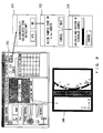
- FIG. 3 schematically illustrates one example of the GUI screen displayed on the display unit 300 at this time.
- the stage control area 320 is an operation area for controlling the XYZ ⁇ electric stage 104.
- the stage control area 320 includes an XY direction button 321, a Z direction button 322, a Z direction slide bar 323, a retract button 324, and a numeric value input part 325.
- the XY direction button 321 is a button for moving the XYZ ⁇ electric stage 104 in the XY direction.
- the Z direction button 322 and the Z direction slide bar 323 are respectively a button and a slide bar for moving the XYZ ⁇ electric stage 104 in the Z direction.
- the retract button 324 is a button for retracting the XYZ ⁇ electric stage 104 to a predetermined position.
- To the numeric value input part 325 XYZ coordinates values for moving the XYZ ⁇ electric stage 104 to a desired XYZ position are input.
- the objective lens control area 330 is an operation area for switching the objective lens 107 in the optical path.
- the objective lens control area 330 includes objective lens buttons 331, 332, 333, 334 and 335 for switching the objective lens 107 in the optical path to any of the objective lenses respectively having magnifications of 4 ⁇ , 10 ⁇ , 20 ⁇ , 40 ⁇ and 60 ⁇ .
- the switching magnification of the objective lens 107 can be changed as needed by suitably selecting objective lenses respectively having desired magnifications and by attaching the objective lenses to the revolver 105.
- a partial area on the GUI screen can be switched to an operation area for performing another operation (such as a voltage adjustment of the light source 101, switching of an observation method, and the like)
- an inverted microscope is adopted as the microscope 100 as described above.
- the electric stage needs to be retracted from the objective lens when the circular sample 103 is set on the electric stage.
- a user can retract the electric stage with a press of the retract button 324 on the GUI screen.
- the electric stage is retracted from the objective lens by a predetermined distance under the control of the control unit 200 with a press of the retract button 324.
- the user can set the predetermined distance, which is a distance according to a limit value of a movable range of the electric stage as an initial setting.
- the predetermined distance is stored in a memory, not illustrated, of the control unit 200.
- the user can retract the electric stage with a manual operation by using the Z axis focus handle 108 when retracting the electric stage.
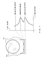
- FIG. 4 illustrates thus calculated graph of the characteristic data.
- the right side of this figure represents the graph of the characteristic data.
- a horizontal axis corresponds to a focus value
- a vertical axis corresponds to a position of the XYZ ⁇ electric stage 104 in the Z direction.
- the left side schematically illustrates a top surface and a cross section of the circular sample 103.
- cells 103a being cultured are represented along with the circular sample 103.
- FIG. 4 schematically illustrates correspondences with the positions in the Z direction with dotted lines between the graph on the right side and the portion representing the cross section of the circular sample 103 on the left side.
- the focus position of the circular sample 103 is automatically aligned in this way.
- the focus position can be aligned manually by using the Z axis focus handle 108.
- the focus position can be aligned by using the Z direction button 322 or the Z direction slide bar 323 on the GUI screen.
- coordinates of the center position of the circular sample 103 set on the XYZ ⁇ electric stage 104 are calculated in S4.
- the coordinates of the center position calculated here are assumed to be an origin of an observation position to be obtained later (the origin on the XY plane).
- the calculation itself of the coordinates of the center position in S4 is performed by using XY coordinates possessed by the XYZ ⁇ electric stage 104.
- the center position of the circular sample 103 is determined. However, if the rotational center position is not the same as the center position or if an electric stage that does not rotate is adopted, the coordinates of the center position of the circular sample 103 need to be calculated. In this embodiment, the case where the rotational center position of the XYZ ⁇ electric stage 104 and the center position of the circular sample 103 are not the same is assumed, and the coordinates of the center position of the circular sample 103 are calculated.
- a position located on an upper side of an observation surface is recognized as the particular position among the plurality of positions.
- the particular position is assumed to have the focus value of 50 percent of the maximum focus value.
- the ratio is not limited to 50 percent.
- the ratio may be arbitrarily set by a user. Otherwise, the particular position may be obtained not in this way but as follows. For example, a distance between a position of the bottom surface of the circular sample 103 and a position of the edge detection surface is prestored in the memory, not illustrated, of the control unit 200.
- the particular position can be obtained based on the distance, and the position of the bottom surface of the circular sample 103 (see the sample bottom surface on the right side of FIG. 4 ) identified with the graph of the characteristic data (see the right side of FIG. 4 ) obtained in S3 of FIG. 2 .
- the order of capturing the two images here is not limited to this one.
- the user can switch the objective lens 107 in the optical path (for example, switch to an objective lens 107 having the lowest magnification) by operating the objective lens control area 330 on the GUI screen so that an image of a desired area is captured.
- the same objective lens 107 in the optical path needs to be used to capture the two images.
- the objective lens 107 in the optical path can be automatically switched to an objective lens 107 having the following magnification when a user presses the center position calculation button 363 on the GUI screen.
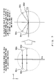
- FIG. 6 is an explanatory view of the edge point detection process executed in S43.
- the edge point detection is performed by filtering a captured image with a differential filter, and by using, as an edge point, a position where an absolute value of the output of the differential filter becomes large.
- a Laplacian filter is used as the differential filter.
- an edge point of the circular sample 103 is further detected from among the detected edge points.
- an edge point 501a positioned on the uppermost side and the rightmost side, and an edge point 501b positioned on the lowermost side and the rightmost side in the image 501 of the area including the edge of the left end of the circular sample 103 are detected as edge points of the circular sample 103.
- an edge point 502a positioned on the uppermost side and the leftmost side, and an edge point 502b positioned on the lowermost side and the leftmost side are detected as edge points of the circular sample 103.
- the coordinates of the center position of the circular sample 103 are calculated from at least four edge points.
- edge points detected as the edge points on the left end side of the circular sample 103 are defined as 501c and 501d
- edge points detected as the edge points on the right end side are defined as 502c and 502d.
- These four edge points have a positional relationship different from the four edge points (501a, 501b, 502a and 502b) illustrated in FIG. 6 .
- the center position can be similarly calculated with the processing method described here.
- the process for calculating the coordinates of the center position of the circular sample 103 is not limited to this one.
- the coordinates can be also calculated by performing an arc approximation with the use of a plurality of edge points.
- the coordinates of the center position of the circular sample 103 can be calculated even though the image of the circular sample 103 cannot be actually captured as a circle when the circular sample 103 is set on the XYZ ⁇ electric stage 104.
- dialog 372 is switched to a dialog 373 "Calculating the center position of the circular sample” the same time the center position coordinates calculation process (S44 of FIG. 5 ) of the circular sample 103 is started based on the specified edge points. If "CANCEL" is selected via the input unit 400 when the dialog 372 or 373 is displayed, the process at that time point is canceled.
- FIG. 9 is an explanatory view of the sample ID new registration performed in S6.
- the dialog 376 for accepting a sample ID input from a user is displayed on the display unit 300.
- This embodiment assumes to accept a sample ID as a file name.
- FIG. 9 illustrates an example where "test1.xxx" is input as a sample ID.
- the user selects "SAVE (S)" in the dialog 376 via the input unit 400, whereby the input sample ID is displayed in the sample ID display field 364 on the GUI screen and stored in the position reproduction information storage unit 208.
- sample ID to be newly registered may be automatically input.
- sample ID to be newly registered automatically can be set, for example, as "user login ID name - date - total number of new registrations.xxx".
- whether the sample ID to be newly registered is either input by a user or automatically input may be arbitrarily changed by a user.
- image capturing is performed under image capturing conditions different from those used when an image of the observation surface to be actually observed is obtained.
- the reason is to more clearly capture an image of a distinctive pattern, a flaw or the like on the bottom surface of the circular sample 103.
- Areas of the captured image portions are used for the pattern matching to be performed later. For example, even though image capturing conditions according to a phase difference observation method, set as an observation method, are set as image capturing conditions when an image on an observation surface is obtained, the observation method is changed to a bright-field observation method when the image of the bottom surface of the circular sample 103 is obtained.
- FIG. 10 illustrates one example of the image of the predetermined area, which is recognized as a reference pattern image, from the image of the bottom surface of the circular sample 103.
- the image of the predetermined area which is recognized as the reference pattern image from the image 511 of the bottom surface of the circular sample 103, is the following image.
- the image of the predetermined area is an image of the area 511b within the circle having a center that is the center 511a of the image 511 of the bottom surface, and having a radius that is the shortest length from the center 511a to an end of the image (the length from the center 511a to the upper or lower end of the image 511 in this example).
- the predetermined area is defined as an area within a circle having a center that is the center of the image of the bottom surface of the circular sample 103, and having a radius that is shorter than the shortest length from the center to an end of the image in order to eliminate the above described possibility.
- the reference pattern image, and the information such as the image capturing conditions, the position in the Z direction, and the like, which are stored here, are used for operations performed later at the second or subsequent observation.
- the reason why the origin of the XY coordinates is changed in this way is as follows. If the circular sample 103 is repeatedly removed/set, the center of the circular sample 103 cannot be always set at the same position on the XYZ ⁇ electric stage 104. Accordingly, it is more convenient to use relative coordinates having an origin that is the center of the circular sample 103 as the XY coordinates of an observation position in order to reproduce the observation position stored at the first observation at the second or subsequent observation.
- a rotational shift of the circular sample 103 set on the XYZ ⁇ electric stage 104 is also taken into account at the second or subsequent observation, and polar coordinates having an origin that is the center of the circular sample 103 are used as relative coordinates.
- the XY coordinates of an observation position P are represented as (R1, ⁇ 1) by using a polar coordinate system having an origin O that is the center position 103b of the circular sample 103.
- R1 is a distance between the origin O and the observation position P
- ⁇ 1 is an angle formed between a horizontal line (a linear line in the horizontal direction of FIG. 12 ) that passes through the origin O and a segment OP.
- the coordinates of the observation position P can be represented also as (R1cos ⁇ 1, R1sin ⁇ 1) with an XY coordinate system having the origin O that is the center position 103b of the circular sample 103.
- FIG. 13 illustrates one example of the GUI screen when an image at an observation position is obtained twice in this way.
- the folder structure is composed of a hierarchical structure of four layers from the first highest layer to the fourth lowest layer.
- a folder of the first layer is a sample ID folder provided for each newly registered sample ID.
- the sample ID folder includes a sample ID (a file having a file name input as a sample ID at the time of new registration) newly registered in S6 of FIG. 2 .
- FIG. 14 illustrates the sample ID folder provided for one newly registered sample ID as a circular sample 1 folder.
- Each sample ID folder includes a reference pattern data folder and a sample reproduction position information folder as folders of the second layer.
- the reference pattern data folder includes the reference pattern image obtained in S7 of FIG.
- Each sample reproduction position information folder includes an observation position folder provided for each observation position as a folder of the third layer.
- each observation position folder includes information such as the coordinates of the observation position, image capturing conditions and the like when the image at the observation position, which is obtained in S8, is captured.
- the observation position folders respectively provided for the observation position 1, the observation position 2 and the observation position 3 are represented as an observation position 1 folder, an observation position 2 folder and an observation position 3 folder.
- Each of the observation position folders includes an observation image folder provided for each observation as a folder of the fourth layer.
- the observation image folders respectively provided for the first, the second and the third observations are represented as a first folder, a second folder and a third folder, respectively.
- the first folder includes the image at the observation position, which is obtained in S8.
- the following information is read from the position reproduction information storage unit 208 (the reference pattern data folder of FIG. 14 ).
- the information is information such as the image capturing conditions, the position of the XYZ ⁇ electric stage 104 in the Z direction, and the like when the reference pattern image obtained at the first observation of the circular sample 103 set on the XYZ ⁇ electric stage 104 is captured. Then, the image capturing conditions, the position of the XYZ ⁇ electric stage 104 in the Z direction, and other items of information when the reference pattern image is captured are reproduced on the microscope 100 based on the information. Moreover, the reference pattern image obtained at the first observation is read from the position reproduction information storage unit 208 (the reference pattern data folder of FIG.
- the user may directly input the sample ID and select "OPEN (O)" in the dialog 377.
- the sample ID is input.
- the sample ID input at this time is displayed in the sample ID display field 364.
- the user selects "CANCEL” in the dialog 377 via the input unit 400, the input of the sample ID at this time point is canceled.
- the dialog 377 is not displayed on the display unit 300 any more.
- the XYZ ⁇ electric stage 104 has already moved to the position when the reference pattern image is captured in the above described S11. With image capturing by the image capturing unit 106, the image, having the center position that is the center position of the circular sample 103, of the bottom surface of the circular sample 103 is obtained.
- a rotational shift angle (a rotational shift amount) between the reference pattern image and the pattern image is calculated.
- the calculation of the rotational shift angle using the pattern matching can be performed, for example, by using a known technique such as an affine transform or the like.
- an image 522 represents the image of the bottom surface of the circular sample 103 including the pattern image 522a when the above described S12 is executed for the circular sample 103 set on the XYZ ⁇ electric stage 104.
- a point 522c represents the center position of the pattern image 522a (also the center position of the image 522).
- Detection of the focused area 522b from the pattern image 522a is performed, for example, by detecting the largest area as an aggregation of pixels having a low brightness value from the pattern image 522a.
- a brightness value threshold value is preset, and an aggregation of pixels having a brightness value smaller than the threshold value is detected from the pattern image 522a, and an area having the largest number of pixels included in the aggregation is detected as a focused area.
- a user may arbitrarily change the brightness value threshold value.
- a rotational angle formed when the area where all the characteristic points of the focused area 522b match is detected from the reference pattern image 521a is calculated as a rotational shift angle between the reference pattern image 521a and the pattern image 522a.
- the pattern matching between the reference pattern image 521a and the focused area 522b of the pattern image 522a is performed as pattern matching performed between the reference pattern image 521a and the pattern image 522a.
- the pattern matching is not limited to this one.
- the image obtained at each observation position is stored in the position reproduction information storage unit 208 (the observation image folder of FIG. 14 ) as an image obtained at the second or subsequent observation in association with the sample ID input in S11.
- the rotational shift correction performed in S14 of FIG. 2 is performed by rotating not the XYZ ⁇ electric stage 104 but the image capturing unit 106.
- FIG. 17 schematically illustrates an entire configuration of a microscope apparatus according to this modification example.
- the microscope 100 further includes a rotation unit 110 in the microscope apparatus according to this modification example.
- the rotation unit 110 rotates the image capturing unit 106 about an optical axis that passes through the center of an image capturing surface as a rotational axis under the control of the control unit 200.
- the rotation unit 110 rotates the image capturing unit 106 under the control of the control unit 200 in S14 of FIG. 2 so that the rotational shift angle calculated in S13 becomes 0 degrees.
- the rotational shift between an image of the circular sample 103, which is obtained at the first observation, and an image of the circular sample 103, which is obtained at the second or subsequent observation is corrected.
- the rotational shift correction in S14 of FIG. 2 is performed by rotating not the XYZ ⁇ electric stage 104 but an image displayed in the image display area 340 on the GUI screen (the image displayed on the display unit 300).
- the display image rotation unit 209 rotates an image of the circular sample 103, which is displayed in the image display area 340 on the GUI screen, under the control of the control unit 200 so that the rotational shift angle calculated in S13 becomes 0 degrees.
- a rotational shift between an image of the circular sample 103 displayed on the display unit 300 at the first observation and an image of the circular sample 103 displayed on the display unit 300 at the second or subsequent observation is corrected.
- an image of a circular sample 103 which has no rotational shift between the first observation and the second or subsequent observation, can be displayed on the display unit 300 similarly to the modification example 1.
- microscope apparatus according to this embodiment can be also modified, for example, as follows as a modification example 3.
- an observation position can be added or deleted at the second or subsequent observation.
- a user can add a new observation position, or deletes an observation position determined to be unnecessary.
- FIG. 19 is a flowchart illustrating operations according to this modification example.
- S21 whether either to add or to delete an observation position is determined. This determination is performed under the control of the control unit 200, for example, by causing a dialog for inquiring of a user about whether either to add or to delete an observation position to be displayed on the display unit 300, and by causing the user to select "YES” or “NO” in the dialog via the input unit 400. If the user selects "YES”, the determination results in “YES” and the flow goes to S22. If the user selects "NO”, the determination results in "NO” and the flow goes to S9.
- the observation position is added or deleted. This addition/deletion is performed under the control of the control unit 200, for example, by displaying a dialog for inquiring of the user about whether either to add or to delete the observation position to be displayed on the display unit 300, and by causing the user to select "ADD" or "DELETE" in the dialog via the input unit 400.
- an observation position to be deleted is selected under the control of the control unit 200. This is performed by causing the user to select a flag icon of the observation position to be deleted from among flag icons displayed in the entire map image area 350 on the GUI screen via the input unit 400.
- the observation position to be deleted is selected in this way, the selected observation position is invalidated, and its image and the like are not automatically obtained at subsequent observations.
- a user can easily add or delete an observation position at the second or subsequent observation.
- the microscope apparatus according to this embodiment can be modified, for example, as follows as a modification example 4.
- processes are executed by excluding an area (also referred to as an unnecessary pattern area) of a portion, not obtained from the circular sample 103, from the pattern image obtained in S12 in S13 of FIG. 2 .
- the area of the portion, not obtained from the circular sample 103 is not detected as a focused area when the focused area (see FIG. 16 ) is detected from the pattern image in S13.
- the area of the portion, not obtained from the circular sample 103 is, for example, an area of a portion caused by an influence of dust in an optical system or a pixel fault or the like of the image capturing unit 106.
- the XYZ ⁇ electric stage 104 is initially rotated in the ⁇ direction under the control of the control unit 200 while a live image of the circular sample 103 is being captured by the image capturing unit 106. At this time, an area that does not rotate with the rotation of the XYZ ⁇ electric stage 104 is detected from the live image, and the detected area is recognized as an area of a portion that is not obtained from the circular sample 103.
- the position of the XYZ ⁇ electric stage 104, the image capturing conditions, and the like when this live image 523 is captured are the same as those when the pattern image is obtained in S12 of FIG. 2 , and a center position 523c of the live image 523 corresponds to the center position of the circular sample 103.
- An image 523' illustrated on the lower side of FIG. 20 is a live image of the circular sample 103, which is captured by the image capturing unit 106 after the XYZ ⁇ electric stage 104 is rotated.
- partial areas 523a' and 523b' within the live image 523' are the two partial areas 523a and 523b after the XYZ ⁇ electric stage 104 is rotated.
- the partial area 523a corresponding to the portion of the circular sample 103 rotates with the rotation of the XYZ ⁇ electric stage 104
- the partial area 523b that is the area where the image of the dust in the optical system is captured does not rotate with the rotation of the XYZ ⁇ electric stage 104. Accordingly, in such a case, the partial area 523 is detected as an area that does not rotate with the rotation of the XYZ ⁇ stage 104, and this area is recognized as an area of a portion that is not obtained from the circular sample 103.
- the processes are executed by excluding this area from the pattern image when detecting a focused area.
- the area recognized as the area of the portion that is not obtained from the circular sample 103 is not detected as a focused area any more.
- an area that does not rotate with the rotation of the XYZ ⁇ electric stage 104 is detected.
- the image capturing unit 106 may be rotated instead of rotating the XYZ ⁇ electric stage 104.
- the configuration applied to the modification example 1 is combined, and the area that does not rotate with the rotation of the image capturing unit 106 is detected from a live image.
- a user may manually rotate a circular sample instead of rotating the XYZ ⁇ electric stage 104. In this case, an area that does not rotate with the user manual rotation of the circular sample is detected from a live image.
- microscope apparatus according to this embodiment can be modified, for example, as follows as a modification example 5.
- FIG. 21 illustrates an example of calculating a rotational shift angle with the pattern matching according to this modification example.
- the example illustrated in this figure is a simple calculation example of calculating the rotational shift angle by performing pattern matching with a method for detecting a pattern image 525a from a reference pattern image 524a.
- an image 525 represents an image of the bottom surface of the circular sample 103 including the pattern image 525a when the above described S12 is executed for the circular sample 103 set on the XYZ ⁇ electric stage 104.
- a point 525b represents the center position (also the center position of the image 525) of the pattern image 525a.
- Detection of the pattern image 525a from the reference pattern image 524a is performed, for example, as follows. The detection is performed by rotating the pattern image 525a about the center position 525b, and by detecting that all character points (such as edge coordinates and the like) of the pattern image 525a match the reference pattern image 524a.
- a culture dish of a biological system is used as the circular sample 103.
- a disc, a circular substrate or the like of an industrial system can be used.
- a microscope such as a digital microscope, a time lapse observation microscope or the like is applicable as the microscope 100.
- an observation position of a circular sample can be reproduced with high accuracy.
Landscapes
- Physics & Mathematics (AREA)
- Engineering & Computer Science (AREA)
- Multimedia (AREA)
- Chemical & Material Sciences (AREA)
- Analytical Chemistry (AREA)
- General Physics & Mathematics (AREA)
- Optics & Photonics (AREA)
- Computer Vision & Pattern Recognition (AREA)
- Microscoopes, Condenser (AREA)
- Image Analysis (AREA)
- Length Measuring Devices By Optical Means (AREA)
- Image Processing (AREA)
Claims (15)
- Mikroskopgerät mit:einer Bildaufnahmeeinheit (106) zum Aufnehmen eines Beobachtungsbilds;eine Zentralpositions-Berechnungseinheit (201) zum Berechnen von Koordinaten einer Zentralposition einer kreisförmigen Probe basierend auf dem Bild der kreisförmigen Probe, das von der Bildaufnahmeeinheit (106) erstellt wird;einer Erkennungseinheit (202) zum Erkennen eines Strukturbilds eines vorbestimmten Bereichs, basierend auf den Koordinaten der Zentralposition, die von der Zentralpositions-Berechnungseinheit (201) berechnet werden, aus dem Bild der kreisförmigen Probe, das von der Bildaufnahmeeinheit (106) erstellt wird;einer Speichereinheit (203) zum Speichern des von der Erkennungseinheit (202) erkannten Strukturbilds;einer Drehverschiebungswinkel-Berechnungseinheit (204) zum Berechnen eines Drehverschiebungswinkels zwischen einem ersten Strukturbild, das von der Erkennungseinheit (202) aus einem Bild der kreisförmigen Probe erkannt wird, welches von der Bildaufnahmeeinheit (106) in einer ersten Periode erstellt wird, und einem zweiten Strukturbild, das von der Erkennungseinheit (202) aus einem Bild der kreisförmigen Probe erkannt wird, welches von der Bildaufnahmeeinheit (106) in einer zweiten, späteren Periode als der ersten Periode erstellt wird; undeiner Positions-Reproduktionseinheit (205) zum Korrigieren einer Drehverschiebung der kreisförmigen Probe, basierend auf dem von der Drehverschiebungswinkel-Berechnungseinheit (204) berechneten Drehverschiebungswinkel, und zum Reproduzieren einer Position der kreisförmigen Probe in der ersten Periode.
- Mikroskopgerät nach Anspruch 1, wobei
die Zentralpositions-Berechnungseinheit (201) mehrere Randpunkte der kreisförmigen Probe aus dem Bild der kreisförmigen Probe, das von der Bildaufnahmeeinheit (106) erstellt wird, erfasst und die Koordinaten der Zentralposition der kreisförmigen Probe basierend auf den mehreren Randpunkten berechnet. - Mikroskopgerät nach Anspruch 1, wobei
die Zentralpositions-Berechnungseinheit (201) die Koordinaten der Zentralposition der kreisförmigen Probe basierend auf den mehreren Randpunkten der kreisförmigen Probe berechnet, die mit einem manuellen Arbeitsgang aus dem Bild der kreisförmigen Probe, das von der Bildaufnahmeeinheit (106) erstellt wird, gewonnen werden. - Mikroskopgerät nach Anspruch 2, wobei
die Zentralpositions-Berechnungseinheit (201) eine Kreisbogenapproximation unter Verwendung der mehreren Randpunkte ausführt, und die Koordinaten der Zentralposition der kreisförmigen Probe berechnet. - Mikroskopgerät nach Anspruch 1, wobei
die Drehverschiebungswinkel-Berechnungseinheit (204) einen Drehverschiebungswinkel zwischen dem ersten Strukturbild und dem zweiten Strukturbild durch Ausführen eines Strukturabgleichs berechnet. - Mikroskopgerät nach Anspruch 1, wobei
die Drehverschiebungswinkel-Berechnungseinheit (204) ein Strukturbild eines bestimmten Bereichs aus dem zweiten Strukturbild unter einer vorbestimmten Bedingung erfasst, das Strukturbild des bestimmten Bereichs um ein Bildzentrum des zweiten Strukturbilds als Drehzentrum dreht und den Drehverschiebungswinkel zwischen dem ersten Strukturbild und dem zweiten Strukturbild aus einem Drehwinkel des Strukturbilds des bestimmten Bereichs berechnet, wenn ein gleiches Strukturbild wie das Strukturbild des bestimmten Bereichs aus dem ersten Strukturbild erfasst wird. - Mikroskopgerät nach Anspruch 1, wobei
der vorbestimmte Bereich auf der Basis eines Bildaufnahmebereichs der Bildaufnahmeeinheit (106) und den Koordinaten der Zentralposition, die von der Zentralpositions-Berechnungseinheit (201) berechnet werden, bestimmt wird. - Mikroskopgerät nach Anspruch 1, wobei
die Positions-Reproduktionseinheit (205) die Drehverschiebung der kreisförmigen Probe durch Drehen der kreisförmigen Probe unter Anwendung der von der Zentralpositions-Berechnungseinheit (201) berechneten Koordinaten der Zentralposition als Ursprung, basierend auf dem von der Drehverschiebungswinkel-Berechnungseinheit (204) berechneten Drehverschiebungswinkel, korrigiert und die Position der kreisförmigen Probe in der ersten Periode reproduziert. - Mikroskopgerät nach Anspruch 1, ferner mit
einer Dreheinheit (110) zum Drehen der Bildaufnahmeeinheit (106), wobei
die Positions-Reproduktionseinheit (205) die Drehverschiebung der kreisförmigen Probe korrigiert, indem sie die Dreheinheit (110) veranlasst, die Bildaufnahmeeinheit (106) basierend auf dem von der Drehverschiebungswinkel-Berechnungseinheit (204) berechneten Drehverschiebungswinkel zu drehen, und die Position der kreisförmigen Probe in der ersten Periode reproduziert. - Mikroskopgerät nach Anspruch 1, ferner mit
einer Anzeigebild-Dreheinheit (209) zum Drehen eines an einer Anzeigeeinheit (300) angezeigten Bilds, wobei
die Positions-Reproduktionseinheit (205) die Drehverschiebung der kreisförmigen Probe korrigiert, indem sie die Anzeigebild-Dreheinheit (209) veranlasst, das an der Anzeigeeinheit (300) angezeigte Bild basierend auf dem von der Drehverschiebungswinkel-Berechnungseinheit (204) berechneten Drehverschiebungswinkel zu drehen, und die Position der kreisförmigen Probe in der ersten Periode reproduziert. - Mikroskopgerät nach Anspruch 6, ferner mit
einer Erfassungseinheit (200) zum Erfassen eines überflüssigen Strukturbereichs, der durch einen Einfluss eines optischen Systems und/oder die Bildaufnahmeeinheit (106) verursacht wird, aus dem durch die Bildaufnahmeeinheit (106) erstellten Bild, wobei
die Drehverschiebungswinkel-Berechnungseinheit (204) einen Prozess ausführt, indem sie den von der Erfassungseinheit (200) zum Erfassen eines überflüssigen Strukturbereichs erfassten überflüssigen Strukturbereich aus dem zweiten Strukturbild ausschließt, wenn sie den Drehverschiebungswinkel zwischen dem ersten Strukturbild und dem zweiten Strukturbild berechnet. - Mikroskopgerät nach Anspruch 1, wobei
das erste Strukturbild von der Erkennungseinheit (202) aus einem Bild einer Bodenfläche der kreisförmigen Probe, das durch die Bildaufnahmeeinheit (106) in der ersten Periode erstellt wird, erkannt wird, und
das zweite Strukturbild von der Erkennungseinheit (202) aus einem Bild einer Bodenfläche der kreisförmigen Probe, das durch die Bildaufnahmeeinheit (106) in der zweiten Periode erstellt wird, erkannt wird. - Beobachtungspositions-Reproduktionsverfahren, umfassend:in einer ersten Periode
Aufnehmen eines Bilds einer kreisförmigen Probe, Berechnen von Koordinaten einer ersten Zentrumsposition der kreisförmigen Probe basierend auf dem erstellten Bild,
Aufnehmen eines Bilds des kreisförmigen Bilds, und Erkennen eines ersten Strukturbilds eines vorbestimmten Bereichs aus dem erstellten Bild, basierend auf den Koordinaten der ersten Zentrumsposition der kreisförmigen Probe; undin einer zweiten, späteren Periode als der ersten Periode,
Aufnehmen eines Bilds der kreisförmigen Probe, Berechnen von Koordinaten einer zweiten Zentrumsposition der kreisförmigen Probe basierend auf dem erstellten Bild,
Aufnehmen eines Bilds der kreisförmigen Probe, Erkennen eines zweiten Strukturbilds eines vorbestimmten Bereichs aus dem erstellten Bild, basierend auf den Koordinaten der zweiten Zentrumsposition der kreisförmigen Probe,Berechnen eines Drehverschiebungswinkels zwischen dem in der ersten Periode erkannten ersten Strukturbild und dem in der zweiten Periode erkannten zweiten Strukturbild,Korrigieren einer Drehverschiebung der kreisförmigen Probe basierend auf dem Drehverschiebungswinkel, und Reproduzieren einer Position der kreisförmigen Probe in der ersten Periode. - Computerlesbares Aufzeichnungsmedium, auf dem sich ein Beobachtungspositions-Reproduktionsprogramm befindet, das einen Computer veranlasst, ein Verfahren auszuführen, wobei das Verfahren umfasst:in einer ersten Periode
Aufnehmen eines Bilds einer kreisförmigen Probe, Berechnen von Koordinaten einer ersten Zentrumsposition der kreisförmigen Probe basierend auf dem erstellten Bild,
Aufnehmen eines Bilds des kreisförmigen Bilds, und Erkennen eines ersten Strukturbilds eines vorbestimmten Bereichs aus dem erstellten Bild, basierend auf den Koordinaten der ersten Zentrumsposition der kreisförmigen Probe; undin einer zweiten, späteren Periode als der ersten Periode,
Aufnehmen eines Bilds der kreisförmigen Probe, Berechnen von Koordinaten einer zweiten Zentrumsposition der kreisförmigen Probe basierend auf dem erstellten Bild,
Aufnehmen eines Bilds der kreisförmigen Probe, Erkennen eines zweiten Strukturbilds eines vorbestimmten Bereichs aus dem erstellten Bild, basierend auf den Koordinaten der zweiten Zentrumsposition der kreisförmigen Probe,Berechnen eines Drehverschiebungswinkels zwischen dem in der ersten Periode erkannten ersten Strukturbild und dem in der zweiten Periode erkannten zweiten Strukturbild,Korrigieren einer Drehverschiebung der kreisförmigen Probe, basierend auf dem Drehverschiebungswinkel, und Reproduzieren einer Position der kreisförmigen Probe in der ersten Periode. - Beobachtungspositions-Reproduktionsprogramm, das einen Computer veranlasst, ein Verfahren auszuführen, wobei das Verfahren umfasst:in einer ersten Periode
Aufnehmen eines Bilds einer kreisförmigen Probe, Berechnen von Koordinaten einer ersten Zentrumsposition der kreisförmigen Probe basierend auf dem erstellten Bild,
Aufnehmen eines Bilds des kreisförmigen Bilds, und Erkennen eines ersten Strukturbilds eines vorbestimmten Bereichs aus dem erstellten Bild, basierend auf den Koordinaten der ersten Zentrumsposition der kreisförmigen Probe; undin einer zweiten, späteren Periode als der ersten Periode
Aufnehmen eines Bilds der kreisförmigen Probe, Berechnen von Koordinaten einer zweiten Zentrumsposition der kreisförmigen Probe basierend auf dem erstellten Bild,
Aufnehmen eines Bilds der kreisförmigen Probe, Erkennen eines zweiten Strukturbilds eines vorbestimmten Bereichs aus dem erstellten Bild, basierend auf den Koordinaten der zweiten Zentrumsposition der kreisförmigen Probe,Berechnen eines Drehverschiebungswinkels zwischen dem in der ersten Periode erkannten ersten Strukturbild und dem in der zweiten Periode erkannten zweiten Strukturbild,Korrigieren einer Drehverschiebung der kreisförmigen Probe, basierend auf dem Drehverschiebungswinkel, und Reproduzieren einer Position der kreisförmigen Probe in der ersten Periode.
Applications Claiming Priority (1)
| Application Number | Priority Date | Filing Date | Title |
|---|---|---|---|
| JP2010047179A JP5479950B2 (ja) | 2010-03-03 | 2010-03-03 | 顕微鏡装置及び観察位置再現方法 |
Publications (2)
| Publication Number | Publication Date |
|---|---|
| EP2363740A1 EP2363740A1 (de) | 2011-09-07 |
| EP2363740B1 true EP2363740B1 (de) | 2012-03-28 |
Family
ID=44063736
Family Applications (1)
| Application Number | Title | Priority Date | Filing Date |
|---|---|---|---|
| EP11001458A Not-in-force EP2363740B1 (de) | 2010-03-03 | 2011-02-22 | Mikroskopgerät und Verfahren zur Reproduktion der Beobachtungsposition |
Country Status (4)
| Country | Link |
|---|---|
| US (1) | US20110216183A1 (de) |
| EP (1) | EP2363740B1 (de) |
| JP (1) | JP5479950B2 (de) |
| AT (1) | ATE551628T1 (de) |
Families Citing this family (17)
| Publication number | Priority date | Publication date | Assignee | Title |
|---|---|---|---|---|
| JP5863357B2 (ja) * | 2011-09-21 | 2016-02-16 | オリンパス株式会社 | 拡大観察装置、並びに、拡大観察装置の画像表示方法及び検鏡法切換方法 |
| JP5841398B2 (ja) * | 2011-10-07 | 2016-01-13 | 株式会社キーエンス | 拡大観察装置 |
| JP2013120108A (ja) * | 2011-12-07 | 2013-06-17 | Sumitomo Heavy Ind Ltd | 薄膜形成装置及び薄膜形成方法 |
| DE102012009257B4 (de) * | 2012-05-02 | 2023-10-05 | Leica Microsystems Cms Gmbh | Verfahren zur Ausführung beim Betreiben eines Mikroskops und Mikroskop |
| KR101384843B1 (ko) * | 2012-09-07 | 2014-05-07 | 주식회사 나노엔텍 | 현미경 및 그 제어방법 |
| JP6455829B2 (ja) * | 2013-04-01 | 2019-01-23 | キヤノン株式会社 | 画像処理装置、画像処理方法、およびプログラム |
| US20180252907A1 (en) * | 2013-06-28 | 2018-09-06 | Discover Echo Inc. | Upright and inverted standing microscope |
| JP6270425B2 (ja) * | 2013-11-18 | 2018-01-31 | オリンパス株式会社 | 位置決め装置、顕微鏡システム、及び付着物除去方法 |
| DE102014210046B4 (de) * | 2014-05-27 | 2021-03-18 | Carl Zeiss Meditec Ag | Operationsmikroskopsystem |
| JP2016049046A (ja) * | 2014-08-29 | 2016-04-11 | 大日本印刷株式会社 | 画像管理装置及びプログラム |
| JP6735645B2 (ja) * | 2016-09-28 | 2020-08-05 | 日本電子株式会社 | 観察方法および試料観察装置 |
| JP6824748B2 (ja) * | 2017-01-05 | 2021-02-03 | オリンパス株式会社 | 顕微鏡パラメータの設定方法および観察方法 |
| JP7060394B2 (ja) * | 2018-02-14 | 2022-04-26 | オリンパス株式会社 | 顕微鏡システム、表示制御方法、及び、プログラム |
| DE102018107033A1 (de) * | 2018-03-23 | 2019-09-26 | Leica Microsystems Cms Gmbh | Mikroskopsystem und Verfahren zur Steuerung eines solchen Mikroskopsystems |
| CN110534389B (zh) * | 2018-05-25 | 2022-05-20 | 中国石油化工股份有限公司 | 可复位样品桩和样品复位方法 |
| JP7412758B2 (ja) * | 2020-04-15 | 2024-01-15 | 日本分光株式会社 | 顕微分光測定装置 |
| WO2024180631A1 (ja) | 2023-02-27 | 2024-09-06 | 大塚電子株式会社 | 情報処理装置、情報処理方法および情報処理プログラム |
Family Cites Families (18)
| Publication number | Priority date | Publication date | Assignee | Title |
|---|---|---|---|---|
| JPH07225843A (ja) | 1994-02-09 | 1995-08-22 | Matsushita Electric Ind Co Ltd | 円中心位置測定方法 |
| US5497007A (en) * | 1995-01-27 | 1996-03-05 | Applied Materials, Inc. | Method for automatically establishing a wafer coordinate system |
| US5870187A (en) * | 1997-08-08 | 1999-02-09 | Applied Materials, Inc. | Method for aligning semiconductor wafer surface scans and identifying added and removed particles resulting from wafer handling or processing |
| JP3859396B2 (ja) * | 1999-07-19 | 2006-12-20 | 日本電子株式会社 | 走査型荷電粒子ビーム装置における試料像観察方法及び走査型荷電粒子ビーム装置 |
| US6711283B1 (en) * | 2000-05-03 | 2004-03-23 | Aperio Technologies, Inc. | Fully automatic rapid microscope slide scanner |
| JP3661604B2 (ja) * | 2001-04-05 | 2005-06-15 | 松下電器産業株式会社 | 顕微観察装置および顕微観察方法 |
| JP2004101871A (ja) * | 2002-09-10 | 2004-04-02 | Olympus Corp | 顕微鏡画像撮影装置 |
| JP2004177325A (ja) * | 2002-11-28 | 2004-06-24 | Keyence Corp | 拡大観察装置、拡大画像観察方法、拡大観察装置操作プログラムおよびコンピュータで読み取り可能な記録媒体 |
| JP3754958B2 (ja) | 2002-12-25 | 2006-03-15 | 独立行政法人科学技術振興機構 | 高倍率顕微観測装置 |
| KR100543468B1 (ko) * | 2003-12-18 | 2006-01-20 | 삼성전자주식회사 | 반도체 패턴의 거리 측정 시스템 및 거리 측정 방법 |
| US7520854B2 (en) * | 2004-07-14 | 2009-04-21 | Olympus Corporation | Endoscope system allowing movement of a display image |
| JP2006091723A (ja) * | 2004-09-27 | 2006-04-06 | Olympus Corp | 倒立顕微鏡 |
| DE102004047519B4 (de) * | 2004-09-28 | 2021-08-12 | Leica Microsystems Cms Gmbh | Verfahren zur Überlagerung optischer Informationen bei einem Scan-Mikroskop |
| JP5059297B2 (ja) * | 2005-05-09 | 2012-10-24 | 株式会社日立ハイテクノロジーズ | 電子線式観察装置 |
| JP4691391B2 (ja) * | 2005-05-12 | 2011-06-01 | 独立行政法人理化学研究所 | 電子顕微鏡 |
| CN101194263B (zh) * | 2005-06-13 | 2012-02-22 | 三路影像公司 | 利用显微镜成像装置再定位载片上样品中的目标的系统和方法 |
| US7630628B2 (en) * | 2007-07-27 | 2009-12-08 | Nikon Corporation | Microscope system and microscope observation method |
| US8089518B2 (en) * | 2007-11-16 | 2012-01-03 | Samsung Electronics Co., Ltd. | System and method for automatic image capture in a handheld camera with a multiple-axis actuating mechanism |
-
2010
- 2010-03-03 JP JP2010047179A patent/JP5479950B2/ja not_active Expired - Fee Related
-
2011
- 2011-02-22 EP EP11001458A patent/EP2363740B1/de not_active Not-in-force
- 2011-02-22 AT AT11001458T patent/ATE551628T1/de active
- 2011-02-25 US US13/034,886 patent/US20110216183A1/en not_active Abandoned
Also Published As
| Publication number | Publication date |
|---|---|
| US20110216183A1 (en) | 2011-09-08 |
| ATE551628T1 (de) | 2012-04-15 |
| JP5479950B2 (ja) | 2014-04-23 |
| JP2011180538A (ja) | 2011-09-15 |
| EP2363740A1 (de) | 2011-09-07 |
Similar Documents
| Publication | Publication Date | Title |
|---|---|---|
| EP2363740B1 (de) | Mikroskopgerät und Verfahren zur Reproduktion der Beobachtungsposition | |
| EP2194414B1 (de) | Mikroskopsystem und Betriebsverfahren dafür | |
| JP5154392B2 (ja) | 撮像装置 | |
| US9245317B2 (en) | Optically enhanced digital imaging system | |
| US20200404186A1 (en) | Defocus amount measuring device, defocus amount measuring method, defocus amount measuring program, and discriminator | |
| US8699129B2 (en) | Microscope system, storage medium storing control program, and control method | |
| JP5997989B2 (ja) | 画像測定装置、その制御方法及び画像測定装置用のプログラム | |
| JP2013072971A (ja) | 顕微鏡システムおよび照明強度調整方法 | |
| JP4878913B2 (ja) | 顕微鏡システム、顕微鏡画像の合成方法、及びプログラム | |
| JP2012042669A (ja) | 顕微鏡制御装置及び光学的歪み補正方法 | |
| US20220309711A1 (en) | Microscopic device and image processing device | |
| JP5205306B2 (ja) | 走査型電子顕微鏡 | |
| JP5730696B2 (ja) | 画像処理装置および画像表示システム | |
| CN116252044A (zh) | 观察装置 | |
| JP4878815B2 (ja) | 顕微鏡装置 | |
| JP5343762B2 (ja) | 制御装置、およびその制御装置を用いた顕微鏡システム | |
| JP5149984B2 (ja) | 撮像装置 | |
| JP2011076960A (ja) | 電子顕微鏡における薄膜試料位置認識装置 | |
| JP5209137B2 (ja) | 撮像装置 | |
| JP2012150142A (ja) | 顕微鏡制御装置、顕微鏡システム及び該制御方法 | |
| JP2013080102A (ja) | 校正具および拡大観察装置 | |
| JP5209097B2 (ja) | 撮像装置 | |
| JP2013072970A (ja) | 顕微鏡システム | |
| JP5155673B2 (ja) | 顕微鏡システム | |
| JP2009237267A (ja) | 顕微鏡システム、顕微鏡システムの制御方法、及びプログラム |
Legal Events
| Date | Code | Title | Description |
|---|---|---|---|
| PUAI | Public reference made under article 153(3) epc to a published international application that has entered the european phase |
Free format text: ORIGINAL CODE: 0009012 |
|
| 17P | Request for examination filed |
Effective date: 20110629 |
|
| AK | Designated contracting states |
Kind code of ref document: A1 Designated state(s): AL AT BE BG CH CY CZ DE DK EE ES FI FR GB GR HR HU IE IS IT LI LT LU LV MC MK MT NL NO PL PT RO RS SE SI SK SM TR |
|
| AX | Request for extension of the european patent |
Extension state: BA ME |
|
| GRAP | Despatch of communication of intention to grant a patent |
Free format text: ORIGINAL CODE: EPIDOSNIGR1 |
|
| RIC1 | Information provided on ipc code assigned before grant |
Ipc: G02B 21/00 20060101ALN20110928BHEP Ipc: G02B 21/36 20060101ALI20110928BHEP Ipc: G02B 21/16 20060101AFI20110928BHEP |
|
| RIC1 | Information provided on ipc code assigned before grant |
Ipc: G02B 21/00 20060101ALN20111012BHEP Ipc: G02B 21/16 20060101AFI20111012BHEP Ipc: G02B 21/36 20060101ALI20111012BHEP |
|
| GRAS | Grant fee paid |
Free format text: ORIGINAL CODE: EPIDOSNIGR3 |
|
| GRAA | (expected) grant |
Free format text: ORIGINAL CODE: 0009210 |
|
| AK | Designated contracting states |
Kind code of ref document: B1 Designated state(s): AL AT BE BG CH CY CZ DE DK EE ES FI FR GB GR HR HU IE IS IT LI LT LU LV MC MK MT NL NO PL PT RO RS SE SI SK SM TR |
|
| REG | Reference to a national code |
Ref country code: GB Ref legal event code: FG4D |
|
| REG | Reference to a national code |
Ref country code: CH Ref legal event code: EP |
|
| REG | Reference to a national code |
Ref country code: AT Ref legal event code: REF Ref document number: 551628 Country of ref document: AT Kind code of ref document: T Effective date: 20120415 |
|
| REG | Reference to a national code |
Ref country code: IE Ref legal event code: FG4D |
|
| REG | Reference to a national code |
Ref country code: DE Ref legal event code: R096 Ref document number: 602011000019 Country of ref document: DE Effective date: 20120524 |
|
| REG | Reference to a national code |
Ref country code: NL Ref legal event code: VDEP Effective date: 20120328 |
|
| PG25 | Lapsed in a contracting state [announced via postgrant information from national office to epo] |
Ref country code: LT Free format text: LAPSE BECAUSE OF FAILURE TO SUBMIT A TRANSLATION OF THE DESCRIPTION OR TO PAY THE FEE WITHIN THE PRESCRIBED TIME-LIMIT Effective date: 20120328 Ref country code: HR Free format text: LAPSE BECAUSE OF FAILURE TO SUBMIT A TRANSLATION OF THE DESCRIPTION OR TO PAY THE FEE WITHIN THE PRESCRIBED TIME-LIMIT Effective date: 20120328 Ref country code: NO Free format text: LAPSE BECAUSE OF FAILURE TO SUBMIT A TRANSLATION OF THE DESCRIPTION OR TO PAY THE FEE WITHIN THE PRESCRIBED TIME-LIMIT Effective date: 20120628 |
|
| LTIE | Lt: invalidation of european patent or patent extension |
Effective date: 20120328 |
|
| PG25 | Lapsed in a contracting state [announced via postgrant information from national office to epo] |
Ref country code: RS Free format text: LAPSE BECAUSE OF FAILURE TO SUBMIT A TRANSLATION OF THE DESCRIPTION OR TO PAY THE FEE WITHIN THE PRESCRIBED TIME-LIMIT Effective date: 20120328 Ref country code: GR Free format text: LAPSE BECAUSE OF FAILURE TO SUBMIT A TRANSLATION OF THE DESCRIPTION OR TO PAY THE FEE WITHIN THE PRESCRIBED TIME-LIMIT Effective date: 20120629 Ref country code: LV Free format text: LAPSE BECAUSE OF FAILURE TO SUBMIT A TRANSLATION OF THE DESCRIPTION OR TO PAY THE FEE WITHIN THE PRESCRIBED TIME-LIMIT Effective date: 20120328 Ref country code: FI Free format text: LAPSE BECAUSE OF FAILURE TO SUBMIT A TRANSLATION OF THE DESCRIPTION OR TO PAY THE FEE WITHIN THE PRESCRIBED TIME-LIMIT Effective date: 20120328 |
|
| REG | Reference to a national code |
Ref country code: AT Ref legal event code: MK05 Ref document number: 551628 Country of ref document: AT Kind code of ref document: T Effective date: 20120328 |
|
| PG25 | Lapsed in a contracting state [announced via postgrant information from national office to epo] |
Ref country code: CY Free format text: LAPSE BECAUSE OF FAILURE TO SUBMIT A TRANSLATION OF THE DESCRIPTION OR TO PAY THE FEE WITHIN THE PRESCRIBED TIME-LIMIT Effective date: 20120328 |
|
| PG25 | Lapsed in a contracting state [announced via postgrant information from national office to epo] |
Ref country code: PL Free format text: LAPSE BECAUSE OF FAILURE TO SUBMIT A TRANSLATION OF THE DESCRIPTION OR TO PAY THE FEE WITHIN THE PRESCRIBED TIME-LIMIT Effective date: 20120328 Ref country code: EE Free format text: LAPSE BECAUSE OF FAILURE TO SUBMIT A TRANSLATION OF THE DESCRIPTION OR TO PAY THE FEE WITHIN THE PRESCRIBED TIME-LIMIT Effective date: 20120328 Ref country code: BE Free format text: LAPSE BECAUSE OF FAILURE TO SUBMIT A TRANSLATION OF THE DESCRIPTION OR TO PAY THE FEE WITHIN THE PRESCRIBED TIME-LIMIT Effective date: 20120328 Ref country code: SE Free format text: LAPSE BECAUSE OF FAILURE TO SUBMIT A TRANSLATION OF THE DESCRIPTION OR TO PAY THE FEE WITHIN THE PRESCRIBED TIME-LIMIT Effective date: 20120328 Ref country code: RO Free format text: LAPSE BECAUSE OF FAILURE TO SUBMIT A TRANSLATION OF THE DESCRIPTION OR TO PAY THE FEE WITHIN THE PRESCRIBED TIME-LIMIT Effective date: 20120328 Ref country code: CZ Free format text: LAPSE BECAUSE OF FAILURE TO SUBMIT A TRANSLATION OF THE DESCRIPTION OR TO PAY THE FEE WITHIN THE PRESCRIBED TIME-LIMIT Effective date: 20120328 Ref country code: IS Free format text: LAPSE BECAUSE OF FAILURE TO SUBMIT A TRANSLATION OF THE DESCRIPTION OR TO PAY THE FEE WITHIN THE PRESCRIBED TIME-LIMIT Effective date: 20120728 Ref country code: SI Free format text: LAPSE BECAUSE OF FAILURE TO SUBMIT A TRANSLATION OF THE DESCRIPTION OR TO PAY THE FEE WITHIN THE PRESCRIBED TIME-LIMIT Effective date: 20120328 |
|
| PG25 | Lapsed in a contracting state [announced via postgrant information from national office to epo] |
Ref country code: SK Free format text: LAPSE BECAUSE OF FAILURE TO SUBMIT A TRANSLATION OF THE DESCRIPTION OR TO PAY THE FEE WITHIN THE PRESCRIBED TIME-LIMIT Effective date: 20120328 Ref country code: PT Free format text: LAPSE BECAUSE OF FAILURE TO SUBMIT A TRANSLATION OF THE DESCRIPTION OR TO PAY THE FEE WITHIN THE PRESCRIBED TIME-LIMIT Effective date: 20120730 |
|
| PG25 | Lapsed in a contracting state [announced via postgrant information from national office to epo] |
Ref country code: DK Free format text: LAPSE BECAUSE OF FAILURE TO SUBMIT A TRANSLATION OF THE DESCRIPTION OR TO PAY THE FEE WITHIN THE PRESCRIBED TIME-LIMIT Effective date: 20120328 Ref country code: NL Free format text: LAPSE BECAUSE OF FAILURE TO SUBMIT A TRANSLATION OF THE DESCRIPTION OR TO PAY THE FEE WITHIN THE PRESCRIBED TIME-LIMIT Effective date: 20120328 Ref country code: AT Free format text: LAPSE BECAUSE OF FAILURE TO SUBMIT A TRANSLATION OF THE DESCRIPTION OR TO PAY THE FEE WITHIN THE PRESCRIBED TIME-LIMIT Effective date: 20120328 |
|
| PLBE | No opposition filed within time limit |
Free format text: ORIGINAL CODE: 0009261 |
|
| STAA | Information on the status of an ep patent application or granted ep patent |
Free format text: STATUS: NO OPPOSITION FILED WITHIN TIME LIMIT |
|
| PG25 | Lapsed in a contracting state [announced via postgrant information from national office to epo] |
Ref country code: IT Free format text: LAPSE BECAUSE OF FAILURE TO SUBMIT A TRANSLATION OF THE DESCRIPTION OR TO PAY THE FEE WITHIN THE PRESCRIBED TIME-LIMIT Effective date: 20120328 |
|
| 26N | No opposition filed |
Effective date: 20130103 |
|
| REG | Reference to a national code |
Ref country code: DE Ref legal event code: R097 Ref document number: 602011000019 Country of ref document: DE Effective date: 20130103 |
|
| PG25 | Lapsed in a contracting state [announced via postgrant information from national office to epo] |
Ref country code: BG Free format text: LAPSE BECAUSE OF FAILURE TO SUBMIT A TRANSLATION OF THE DESCRIPTION OR TO PAY THE FEE WITHIN THE PRESCRIBED TIME-LIMIT Effective date: 20120628 |
|
| PG25 | Lapsed in a contracting state [announced via postgrant information from national office to epo] |
Ref country code: MC Free format text: LAPSE BECAUSE OF NON-PAYMENT OF DUE FEES Effective date: 20130228 |
|
| PG25 | Lapsed in a contracting state [announced via postgrant information from national office to epo] |
Ref country code: ES Free format text: LAPSE BECAUSE OF FAILURE TO SUBMIT A TRANSLATION OF THE DESCRIPTION OR TO PAY THE FEE WITHIN THE PRESCRIBED TIME-LIMIT Effective date: 20120709 |
|
| REG | Reference to a national code |
Ref country code: FR Ref legal event code: ST Effective date: 20131031 |
|
| REG | Reference to a national code |
Ref country code: IE Ref legal event code: MM4A |
|
| PG25 | Lapsed in a contracting state [announced via postgrant information from national office to epo] |
Ref country code: AL Free format text: LAPSE BECAUSE OF FAILURE TO SUBMIT A TRANSLATION OF THE DESCRIPTION OR TO PAY THE FEE WITHIN THE PRESCRIBED TIME-LIMIT Effective date: 20120328 Ref country code: IE Free format text: LAPSE BECAUSE OF NON-PAYMENT OF DUE FEES Effective date: 20130222 Ref country code: FR Free format text: LAPSE BECAUSE OF NON-PAYMENT OF DUE FEES Effective date: 20130228 |
|
| PG25 | Lapsed in a contracting state [announced via postgrant information from national office to epo] |
Ref country code: MT Free format text: LAPSE BECAUSE OF FAILURE TO SUBMIT A TRANSLATION OF THE DESCRIPTION OR TO PAY THE FEE WITHIN THE PRESCRIBED TIME-LIMIT Effective date: 20120328 |
|
| REG | Reference to a national code |
Ref country code: CH Ref legal event code: PL |
|
| PG25 | Lapsed in a contracting state [announced via postgrant information from national office to epo] |
Ref country code: LI Free format text: LAPSE BECAUSE OF NON-PAYMENT OF DUE FEES Effective date: 20140228 Ref country code: CH Free format text: LAPSE BECAUSE OF NON-PAYMENT OF DUE FEES Effective date: 20140228 |
|
| PG25 | Lapsed in a contracting state [announced via postgrant information from national office to epo] |
Ref country code: SM Free format text: LAPSE BECAUSE OF FAILURE TO SUBMIT A TRANSLATION OF THE DESCRIPTION OR TO PAY THE FEE WITHIN THE PRESCRIBED TIME-LIMIT Effective date: 20120328 |
|
| PG25 | Lapsed in a contracting state [announced via postgrant information from national office to epo] |
Ref country code: TR Free format text: LAPSE BECAUSE OF FAILURE TO SUBMIT A TRANSLATION OF THE DESCRIPTION OR TO PAY THE FEE WITHIN THE PRESCRIBED TIME-LIMIT Effective date: 20120328 |
|
| PG25 | Lapsed in a contracting state [announced via postgrant information from national office to epo] |
Ref country code: LU Free format text: LAPSE BECAUSE OF NON-PAYMENT OF DUE FEES Effective date: 20130222 Ref country code: HU Free format text: LAPSE BECAUSE OF FAILURE TO SUBMIT A TRANSLATION OF THE DESCRIPTION OR TO PAY THE FEE WITHIN THE PRESCRIBED TIME-LIMIT; INVALID AB INITIO Effective date: 20110222 Ref country code: MK Free format text: LAPSE BECAUSE OF FAILURE TO SUBMIT A TRANSLATION OF THE DESCRIPTION OR TO PAY THE FEE WITHIN THE PRESCRIBED TIME-LIMIT Effective date: 20120328 |
|
| GBPC | Gb: european patent ceased through non-payment of renewal fee |
Effective date: 20150222 |
|
| PG25 | Lapsed in a contracting state [announced via postgrant information from national office to epo] |
Ref country code: GB Free format text: LAPSE BECAUSE OF NON-PAYMENT OF DUE FEES Effective date: 20150222 |
|
| PGFP | Annual fee paid to national office [announced via postgrant information from national office to epo] |
Ref country code: DE Payment date: 20190219 Year of fee payment: 9 |
|
| REG | Reference to a national code |
Ref country code: DE Ref legal event code: R119 Ref document number: 602011000019 Country of ref document: DE |
|
| PG25 | Lapsed in a contracting state [announced via postgrant information from national office to epo] |
Ref country code: DE Free format text: LAPSE BECAUSE OF NON-PAYMENT OF DUE FEES Effective date: 20200901 |