EP2363766A2 - Timepiece cover glass and timepiece - Google Patents
Timepiece cover glass and timepiece Download PDFInfo
- Publication number
- EP2363766A2 EP2363766A2 EP11151088A EP11151088A EP2363766A2 EP 2363766 A2 EP2363766 A2 EP 2363766A2 EP 11151088 A EP11151088 A EP 11151088A EP 11151088 A EP11151088 A EP 11151088A EP 2363766 A2 EP2363766 A2 EP 2363766A2
- Authority
- EP
- European Patent Office
- Prior art keywords
- cover glass
- timepiece
- solar battery
- wavelength
- reflectance
- Prior art date
- Legal status (The legal status is an assumption and is not a legal conclusion. Google has not performed a legal analysis and makes no representation as to the accuracy of the status listed.)
- Granted
Links
Images


Classifications
-
- G—PHYSICS
- G04—HOROLOGY
- G04C—ELECTROMECHANICAL CLOCKS OR WATCHES
- G04C10/00—Arrangements of electric power supplies in time-pieces
- G04C10/02—Arrangements of electric power supplies in time-pieces the power supply being a radioactive or photovoltaic source
-
- C—CHEMISTRY; METALLURGY
- C03—GLASS; MINERAL OR SLAG WOOL
- C03C—CHEMICAL COMPOSITION OF GLASSES, GLAZES OR VITREOUS ENAMELS; SURFACE TREATMENT OF GLASS; SURFACE TREATMENT OF FIBRES OR FILAMENTS MADE FROM GLASS, MINERALS OR SLAGS; JOINING GLASS TO GLASS OR OTHER MATERIALS
- C03C17/00—Surface treatment of glass, not in the form of fibres or filaments, by coating
- C03C17/34—Surface treatment of glass, not in the form of fibres or filaments, by coating with at least two coatings having different compositions
- C03C17/3411—Surface treatment of glass, not in the form of fibres or filaments, by coating with at least two coatings having different compositions with at least two coatings of inorganic materials
- C03C17/3429—Surface treatment of glass, not in the form of fibres or filaments, by coating with at least two coatings having different compositions with at least two coatings of inorganic materials at least one of the coatings being a non-oxide coating
- C03C17/3435—Surface treatment of glass, not in the form of fibres or filaments, by coating with at least two coatings having different compositions with at least two coatings of inorganic materials at least one of the coatings being a non-oxide coating comprising a nitride, oxynitride, boronitride or carbonitride
-
- G—PHYSICS
- G04—HOROLOGY
- G04G—ELECTRONIC TIME-PIECES
- G04G17/00—Structural details; Housings
- G04G17/02—Component assemblies
-
- C—CHEMISTRY; METALLURGY
- C03—GLASS; MINERAL OR SLAG WOOL
- C03C—CHEMICAL COMPOSITION OF GLASSES, GLAZES OR VITREOUS ENAMELS; SURFACE TREATMENT OF GLASS; SURFACE TREATMENT OF FIBRES OR FILAMENTS MADE FROM GLASS, MINERALS OR SLAGS; JOINING GLASS TO GLASS OR OTHER MATERIALS
- C03C2217/00—Coatings on glass
- C03C2217/70—Properties of coatings
- C03C2217/73—Anti-reflective coatings with specific characteristics
- C03C2217/734—Anti-reflective coatings with specific characteristics comprising an alternation of high and low refractive indexes
-
- C—CHEMISTRY; METALLURGY
- C03—GLASS; MINERAL OR SLAG WOOL
- C03C—CHEMICAL COMPOSITION OF GLASSES, GLAZES OR VITREOUS ENAMELS; SURFACE TREATMENT OF GLASS; SURFACE TREATMENT OF FIBRES OR FILAMENTS MADE FROM GLASS, MINERALS OR SLAGS; JOINING GLASS TO GLASS OR OTHER MATERIALS
- C03C2218/00—Methods for coating glass
- C03C2218/30—Aspects of methods for coating glass not covered above
- C03C2218/365—Coating different sides of a glass substrate
Definitions
- the invention relates to a timepiece cover glass and to a timepiece.
- Timepieces with solar batteries which do not require battery replacement have recently come into use.
- the solar battery is disposed on a face plate or a base plate, and is covered by a cover glass.
- Patent document 1 discloses a timepiece cover glass having an outermost antireflective film obtained by introducing nitrogen into a SiO 2 film to improve visibility.
- the antireflective film is provided on a glass substrate.
- Patent Document 1 Japanese Laid-open Patent Application No. 2004-198354 is an example of the related art.
- the present invention provides a timepiece cover glass in which the face plate and hands have excellent visibility and the solar battery has excellent power generation efficiency. Further provided is a timepiece comprising a solar battery and the afore-mentioned timepiece cover glass.
- the inventors have discovered that if there is too great a difference between (i) the minimum reflectance wavelength of the antireflective layer of the timepiece cover glass, (ii) the maximum visible sensitivity wavelength, and (iii) the maximum sensitivity wavelength of the solar battery, the visibility of the face plate and hands is insufficient and/or the power generation efficiency of the solar battery is insufficient.
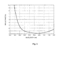
- the wavelength at minimum reflectance of the antireflective layer was 650 nm (see FIG. 3 ), a deviation of about 100 nm from both the 550 nm wavelength of maximum sensitivity visible to the human eye and the 520 nm wavelength of maximum sensitivity of an amorphous silicon solar battery.
- reflectance curve refers to a curve that represents reflectance at various wavelengths of visible light, and also refers to a reflectance spectrum.
- wavelength exhibiting minimum reflectance (minimum reflectance wavelength)” refers to the wavelength when the reflectance exhibits the minimum value in the reflectance curve. In cases of multiple minimum values, the wavelength considered to be the wavelength exhibiting minimum reflectance is the center wavelength between two points that is intersected by a straight line parallel to the wavelength axis at a reflectance of 2%.
- maximum visible sensitivity wavelength of the solar battery refers to the wavelength when sensitivity of the human eye reaches a maximum, and is assigned a value of 550 nm.
- the inventors discovered that by forming an antireflective film in which the wavelength difference is within a predetermined range on the timepiece cover glass, visibility of the face plate and hands is improved, as is the power generation efficiency of the solar battery.
- the invention is a timepiece cover glass for use in a timepiece comprising a solar battery, the timepiece cover glass covering the solar battery, the timepiece cover glass comprising an antireflective layer formed on both sides of the timepiece cover glass, wherein
- the wavelength of minimum reflectance of the antireflective film of the timepiece cover glass and the maximum sensitivity wavelength of the solar battery is kept within a difference of 40 nm or less with respect to the wavelength of maximum visible sensitivity (the maximum wavelength of visible sensitivity of the human eye is 550 nm), and the luminous reflectance is 0.6% or less; therefore, the visibility of the face plate and the hands can be improved as can the power generation efficiency of the solar battery.
- luminous reflectance refers to a value of reflectance that is the average of reflectances at various wavelengths of the visible light range, which are modified according to luminosity.
- the wavelength considered to be the wavelength exhibiting the minimum reflectance is the center wavelength between two points on the reflectance curve that is intersected by a straight line running parallel to the wavelength axis at a reflectance of 2%.
- the reflectance curve has two or more minimum values
- the center wavelength is considered to be the minimum reflectance wavelength as in the invention, formula (1) above is satisfied, and the luminous reflectance is 0.6% or less, the visibility of the face plate and hands can be improved as can the power generation efficiency of the solar battery.
- the antireflective layer is preferably an inorganic multilayer film comprising one or more high-refraction layers and one ore more low-refraction layers stacked in an alternating fashion.
- the antireflective layer when the antireflective layer is formed by alternately stacking high-refraction layers and low-refraction layers, reflectance can be reduced and the antireflective effect can be improved. Furthermore, it is easy to control the antireflective effect and light transmittance by increasing or decreasing the number of stacked layers.
- the high-refraction layer comprises silicon nitride and the low-refraction layer comprises silicon oxide.
- the antireflective layer when configured by alternately stacking high-refraction layers composed of silicon nitride and low-refraction layers composed of silicon oxide, the antireflective effect and scratch resistance can be improved.
- timepiece comprising a solar battery and a timepiece cover glass according to the invention described above.
- timepiece cover glass in which the face plate and hands have excellent visibility and the solar battery has excellent power generation efficiency, as well as to provide as a timepiece including this timepiece cover glass.
- FIG. 1 is a schematic view showing a cross section of the cover glass according to an embodiment of the invention
- FIG. 2 is a cross-sectional view of a timepiece including the cover glass according to the present invention.
- FIG. 3 is a view of a reflectance curve of an antireflective film of a timepiece cover glass according to the prior art.
- FIG. 1 is a schematic view showing a cross section of a timepiece cover glass 10 ("cover glass 10" below) according to an embodiment of the invention.
- the cover glass 10 includes a transparent substrate 11, and an antireflective layer 12 formed on top of the substrate.
- the substrate 11 is made of an inorganic oxide, possible examples of which including sapphire glass, quartz glass, soda glass, and the like. Sapphire glass in particular is preferable as the material of the cover glass 10 for its hardness and transparency.
- the antireflective layer 12 is formed on the top of the substrate 11, and is a multilayer film obtained by alternately stacking inorganic thin films having different refractive indexes.
- the antireflective layer 12 is composed of five layers, stacked up from the substrate 11 in the following sequence: 12A (a low-refraction layer), 12B (a high-refraction layer), 12C (a low-refraction layer), 12D (a high-refraction layer), and 12E (a low-refraction layer). These five layers are formed on both sides of the substrate 11.
- the high-refraction layers 12B, 12D are formed from silicon nitride (SiNx), and the low-refraction layers 12A. 12C, 12E are formed from silicon oxide (SiO 2 ).
- An antireflective layer having the desired minimum reflectance wavelength and luminous reflectance can be obtained by appropriately setting the stacked configuration of the antireflective layer (the material, the number of layers, the stacking sequence, and the refractive indexes of the layers) using an optical design simulation or another method.
- the reflectance of the antireflective layer 12 is measured using a spectrophotometer, and a reflectance curve is drawn.
- the wavelength occurring when the minimum reflectance is exhibited in this reflectance curve is designated as the minimum reflectance wavelength.
- the wavelength considered to be the minimum reflectance wavelength is a center wavelength between two points on the reflectance curve that can be intersected by a straight line parallel to the wavelength axis at a reflectance of 2%.
- the thickness of the outermost layer (the low-refraction layer 12E) composed of silicon oxide is preferably 70 to 110 nm, or more preferably 75 to 105 nm.
- the thickness of the silicon nitride layer (the high-refraction layer 12D) adjacent to the outermost layer is preferably 50 to 115 nm, or more preferably 55 to 110 nm. If the layer thicknesses are outside of these ranges, the reflectance of the antireflective layer tends to increase.
- sputtering is used.
- the usual method used when forming an inorganic thin film can be applied as the sputtering, but in the present embodiment, high-frequency sputtering is performed in an atmosphere of Ar gas, nitrogen gas, or another inert gas, with Si as the target, forming high-refraction layers 12B, 12D composed of silicon nitride; and high-frequency sputtering is performed in a mixed gas atmosphere composed of oxygen gas and Ar, forming low-refraction layers 12A, 12C, 12E composed of silicon oxide.
- the antireflective layer 12 composed of the five previously described layers is formed on both sides of the substrate 11, and the cover glass 10 is thereby manufactured.
- a heating step for heating the substrate 11 to 100°C or greater for the sake of improving the hardness and adhesiveness of the antireflective film.
- a reverse sputtering step for removing accretions on the surface of the substrate 11 before the antireflective layer 12 is formed by sputtering, because the surface of the substrate 11 can be washed.
- FIG. 2 shows a cross-sectional view of a timepiece including the cover glass 10.
- the cover glass 10 is provided on a case 14 for housing the timepiece body (movement) 13.
- a back cover 15 is provided to the case 14.
- the bulk surface portion of the cover glass 10 of the present embodiment is herein composed of a front surface part 10A, a rear surface part 10B, and a side surface part 10C.
- the front surface part 10A is equivalent to an outer side portion of the cover glass 10.
- the rear surface part 10B is equivalent to an inner side portion of the cover glass 10, and is made to face a face plate 16 and indicator hands 17.
- the previously-described antireflective layers 12 are positioned on the front surface part 10A and the rear surface part 10B of the cover glass 10.
- a solar battery 18 is mounted on the face plate 16 as shown in FIG. 2 .
- a light-receiving surface 18a of the solar battery 18 faces the rear surface part 10B of the cover glass 10.
- the peak of the sensitivity (maximum sensitivity) of the solar battery 18 differs depending on the type of solar battery.
- an amorphous silicon solar battery (a-Si solar battery) has a sensitivity peak in the visible light wavelength range
- a single-crystal silicon solar battery c-Si solar battery
- the wavelength at the sensitivity peak (maximum sensitivity) is referred to as the maximum sensitivity wavelength.
- an a-Si solar battery is used, and the maximum sensitivity wavelength is in a range of approximately 510 to 530 nm.
- the minimum reflectance wavelength x (nm) of the antireflective layer 12 and the maximum sensitivity wavelength y (nm) of the solar battery 18 satisfy the formula below with the maximum visible sensitivity wavelength (550 nm) which is the wavelength of light that can be perceived most strongly by the human eye, and the luminous reflectance is 0.6% or less.
- f x ⁇ y ⁇ 550 ⁇ 40 (The formula f (x, y, 550) herein expresses the absolute value of the difference between the maximum and minimum values among x, y, and 550.)
- the relationships of the wavelength differences between the reflectance center wavelength of the antireflective layers 12 positioned on the front surface part 10A and rear surface part 10B of the cover glass 10, the maximum sensitivity wavelength of the solar battery 18 mounted on the face plate 16, and the maximum visible sensitivity wavelength satisfy formula (2) above, and the luminous reflectance is 0.6% or less; therefore, the visibility of the face plate and hands and the power generation efficiency of the solar battery can be improved.
- the antireflective layer 12 is an inorganic multilayer film made by alternately stacking the high-refraction layers 12B, 12D and the low-refraction layers 12A, 12C, 12E, there is little reflection of light from the cover glass 10, and an excellent antireflective effect can be achieved.
- the antireflective effect and scratch resistance can be improved because the high-refraction layers 12B, 12D are composed of silicon nitride and the low-refraction layers 12A, 12C, 12E are composed of silicon oxide.
- antireflective layers 12 are positioned on the front surface part 10A and rear surface part 10B of the cover glass 10, visibility and power generation efficiency of the solar battery are further improved than when an antireflective layer 12 is positioned on only one of either the front surface part 10A or rear surface part 10B of the cover glass 10.
- the configurations of the antireflective layers 12 positioned on the front surface part 10A and rear surface part 10B of the cover glass 10 are formed to be symmetrical about the substrate 11, but are not limited to this formation, and the number of films and materials may differ between the front surface and back surface of the substrate 11.
- the configuration on the front surface side of the substrate 11 be in the sequence of 12A (a low-refraction layer), 12B (a high-refraction layer), 12C (a low-refraction layer), 12D (a high-refraction layer), and 12E (a low-refraction layer), starting from the substrate.
- the solar battery 18 is mounted on part of the face plate 16 and the light-receiving surface 18a of the solar battery 18 faces the rear surface part 10B of the cover glass 10 as shown in FIG. 2 , but the configuration is not limited to this example.
- nearly the entire top surface of the face plate may be fashioned into a light-receiving surface, or the light-receiving surface may be covered by a translucent member and an insignia, alphanumeric characters, or the like may be formed in this translucent member to create the face plate, ensuring an amount of light transmission and improving the design.
- Another option is a configuration in which a solar battery is mounted on the back surface side of the face plate and light passing through the cover glass is guided to the light-receiving surface by a light-guiding plate or another light-guiding member provided in the edge vicinity of the face plate, which may ensure an amount of light directed onto the light-receiving surface and further improve the design of the face plate.
- high hardness sapphire glass is preferred as the substrate of the translucent member, but the use of quartz glass, soda glass, and other types of glass may also be considered.
- the cover glass of the invention is not limited to a cover member used in a timepiece, and can also be suitably used as a cover member of an information display in cellular telephones, portable information devices, measurement devices, digital cameras, and other various devices having a solar battery.
- the sapphire glass was immersed for ten minutes in hot concentrated sulfuric acid at 120°C, then washed well with pure water, and dried for 30 minutes at atmospheric pressure in an oven set to 120°C. Next, the sapphire glass was placed inside a sputtering apparatus, and the interior of the apparatus was brought to a pressure of 10 -6 Torr while being heated to 120°C. Ar gas was then introduced into the apparatus, and the surface of the sapphire glass was cleaned by reverse sputtering at 0.8 mTorr.
- an antireflective layer composed of high-refraction layers and low-refraction layers (four to nine layers, on one side or both sides) was formed on the surface of a substrate made of sapphire glass.
- antireflective layers were formed on both sides of the sapphire glass substrate, and for the comparative examples, either antireflective layers were not formed on the substrate or an antireflective layer was formed on only one side.
- Table 1 shows the specific configurations (types of layers, number of layers, thickness of layers) of the antireflective layers, the luminous reflectances of the antireflective layers of the various configurations, and the minimum reflectance wavelengths. Furthermore, for Working Examples 1 to 11 and Comparative Examples 1 to 2, Table 1 shows the maximum and minimum values of the minimum reflectance wavelengths x (nm), the maximum sensitivity wavelengths y (nm) of the solar batteries, and the wavelengths in the maximum visible sensitivity wavelengths z (nm); as well as the values of f (x, y, z), which is the absolute value of the difference between the maximum value and the minimum value.
- the reflectance of reference light incident at an angle of 90° relative to the substrate surface was found, and the luminous reflectance was calculated based on an integrated value of a value obtained by multiplying the reference reflectance by the visible sensitivity for the incident angle of 90° for various wavelengths in the visible light range.
- the reflectance was measured using an USPM-RU lens reflectance measurement device (Olympus Optical).
- a solar battery was placed facing the back surface side of the sapphire glass substrate having the antireflective layer shown in Table 1, and the power generation efficiency was measured by exposure to light from the front surface side of the sapphire glass substrate.
- the power generation efficiency was measured according to JIS C 8907.
- amorphous silicon batteries AT-2600B (Sanyo Electric) were used as the solar batteries.
- the maximum sensitivity wavelengths of the solar batteries were 510 nm, 520 nm, and 530 nm, respectively.
- Table 1 shows the results of measuring power generation efficiency using a solar battery whose maximum sensitivity wavelength is 510 nm for the sapphire glass substrates having antireflective layers as well as the sapphire glass substrates not having antireflective layers in Working Examples 1 to 11 and Comparative Examples 1 to 2.
- Table 2 shows the results of measuring power generation efficiency using a solar battery whose maximum sensitivity wavelength is 520 nm, as well as f(x, y, z) in Working Examples 12 to 22 and Comparative Examples 3 to 4; while Table 3 similarly shows the results of measuring power generation efficiency using a solar battery whose maximum sensitivity wavelength is 530 nm, as well as f(x, y, z) in Working Examples 23 to 33 and Comparative Examples 5 to 6.
Landscapes
- Chemical & Material Sciences (AREA)
- Engineering & Computer Science (AREA)
- Physics & Mathematics (AREA)
- General Physics & Mathematics (AREA)
- Life Sciences & Earth Sciences (AREA)
- Chemical Kinetics & Catalysis (AREA)
- General Chemical & Material Sciences (AREA)
- Geochemistry & Mineralogy (AREA)
- Materials Engineering (AREA)
- Organic Chemistry (AREA)
- Power Engineering (AREA)
- Surface Treatment Of Glass (AREA)
Abstract
Description
- This application claims priority to Japanese Patent Application No.
2010-008810 filed on January 19, 2010 2010-00810 - The invention relates to a timepiece cover glass and to a timepiece.
- Timepieces with solar batteries which do not require battery replacement have recently come into use. In a timepiece with a solar battery, the solar battery is disposed on a face plate or a base plate, and is covered by a cover glass.
- There is demand to improve not only the visibility of the face plate and the hands in timepieces with solar batteries, but also the power generation efficiency of the solar battery.
-
Patent document 1 discloses a timepiece cover glass having an outermost antireflective film obtained by introducing nitrogen into a SiO2 film to improve visibility. The antireflective film is provided on a glass substrate. - Japanese Laid-open Patent Application No.
2004-198354 - However, even when the timepiece cover glass having an antireflective film disclosed in
Patent Document 1 is used as the cover glass of a timepiece with a solar battery, it has been difficult to simultaneously satisfy the demand for visibility of the face plate and hands and the demand for power generation efficiency of the solar battery. - The present invention provides a timepiece cover glass in which the face plate and hands have excellent visibility and the solar battery has excellent power generation efficiency. Further provided is a timepiece comprising a solar battery and the afore-mentioned timepiece cover glass.
- The inventors have discovered that if there is too great a difference between (i) the minimum reflectance wavelength of the antireflective layer of the timepiece cover glass, (ii) the maximum visible sensitivity wavelength, and (iii) the maximum sensitivity wavelength of the solar battery, the visibility of the face plate and hands is insufficient and/or the power generation efficiency of the solar battery is insufficient. For example, when using a timepiece cover glass having the configuration of the antireflective layer disclosed in
Patent Document 1, it was clear that the visibility of the face plate and hands was insufficient as was the power generation efficiency of the solar battery. In that cover glass, the wavelength at minimum reflectance of the antireflective layer was 650 nm (seeFIG. 3 ), a deviation of about 100 nm from both the 550 nm wavelength of maximum sensitivity visible to the human eye and the 520 nm wavelength of maximum sensitivity of an amorphous silicon solar battery. - The term "reflectance curve" refers to a curve that represents reflectance at various wavelengths of visible light, and also refers to a reflectance spectrum. The term "wavelength exhibiting minimum reflectance (minimum reflectance wavelength)" refers to the wavelength when the reflectance exhibits the minimum value in the reflectance curve. In cases of multiple minimum values, the wavelength considered to be the wavelength exhibiting minimum reflectance is the center wavelength between two points that is intersected by a straight line parallel to the wavelength axis at a reflectance of 2%. Furthermore, the term "maximum visible sensitivity wavelength of the solar battery" refers to the wavelength when sensitivity of the human eye reaches a maximum, and is assigned a value of 550 nm.
- The inventors discovered that by forming an antireflective film in which the wavelength difference is within a predetermined range on the timepiece cover glass, visibility of the face plate and hands is improved, as is the power generation efficiency of the solar battery.
- The invention was completed based on the above findings.
- The invention is a timepiece cover glass for use in a timepiece comprising a solar battery, the timepiece cover glass covering the solar battery, the timepiece cover glass comprising
an antireflective layer formed on both sides of the timepiece cover glass, wherein - (i) formula (1) below is satisfied by the antireflective layer:

where (f(x, y, z) expresses the absolute value of the difference between the maximum value and minimum value among x, y, and z);
x represents a wavelength (nm) exhibiting a minimum reflectance in a reflectance curve based on the antireflective layer,
y represents a maximum sensitivity wavelength (nm) of the solar battery, and
z represents a maximum visible sensitivity wavelength of the solar battery (nm) and has a value of 550; and - (ii) the luminous reflectance of the antireflective layer is 0.6% or less.
- According to the invention, by satisfying formula (1) with the difference between the wavelength of minimum reflectance of the antireflective film of the timepiece cover glass, the wavelength of maximum visible sensitivity, and maximum sensitivity wavelength of the solar battery, the wavelength of minimum reflectance of the antireflective film of the timepiece cover glass and the maximum sensitivity wavelength of the solar battery is kept within a difference of 40 nm or less with respect to the wavelength of maximum visible sensitivity (the maximum wavelength of visible sensitivity of the human eye is 550 nm), and the luminous reflectance is 0.6% or less; therefore, the visibility of the face plate and the hands can be improved as can the power generation efficiency of the solar battery.
- The term "luminous reflectance" refers to a value of reflectance that is the average of reflectances at various wavelengths of the visible light range, which are modified according to luminosity.
- In the invention, it is preferable that the wavelength considered to be the wavelength exhibiting the minimum reflectance is the center wavelength between two points on the reflectance curve that is intersected by a straight line running parallel to the wavelength axis at a reflectance of 2%.
- According to the invention, when the reflectance curve has two or more minimum values, if the center wavelength is considered to be the minimum reflectance wavelength as in the invention, formula (1) above is satisfied, and the luminous reflectance is 0.6% or less, the visibility of the face plate and hands can be improved as can the power generation efficiency of the solar battery.
- Furthermore, in the invention, the antireflective layer is preferably an inorganic multilayer film comprising one or more high-refraction layers and one ore more low-refraction layers stacked in an alternating fashion.
- According to the invention, when the antireflective layer is formed by alternately stacking high-refraction layers and low-refraction layers, reflectance can be reduced and the antireflective effect can be improved. Furthermore, it is easy to control the antireflective effect and light transmittance by increasing or decreasing the number of stacked layers.
- In the invention it is preferable that the high-refraction layer comprises silicon nitride and the low-refraction layer comprises silicon oxide.
- According to the invention, when the antireflective layer is configured by alternately stacking high-refraction layers composed of silicon nitride and low-refraction layers composed of silicon oxide, the antireflective effect and scratch resistance can be improved.
- Also provided is a timepiece comprising a solar battery and a timepiece cover glass according to the invention described above.
- According to the invention, it is possible to provide a timepiece in which the face plate and hands have excellent visibility and the solar battery has excellent power generation efficiency.
- According to the invention, it is possible to provide a timepiece cover glass in which the face plate and hands have excellent visibility and the solar battery has excellent power generation efficiency, as well as to provide as a timepiece including this timepiece cover glass.
-
FIG. 1 is a schematic view showing a cross section of the cover glass according to an embodiment of the invention; -
FIG. 2 is a cross-sectional view of a timepiece including the cover glass according to the present invention; and -
FIG. 3 is a view of a reflectance curve of an antireflective film of a timepiece cover glass according to the prior art. -
FIG. 1 is a schematic view showing a cross section of a timepiece cover glass 10 ("cover glass 10" below) according to an embodiment of the invention. Thecover glass 10 includes atransparent substrate 11, and anantireflective layer 12 formed on top of the substrate. - The
substrate 11 is made of an inorganic oxide, possible examples of which including sapphire glass, quartz glass, soda glass, and the like. Sapphire glass in particular is preferable as the material of thecover glass 10 for its hardness and transparency. - The
antireflective layer 12 is formed on the top of thesubstrate 11, and is a multilayer film obtained by alternately stacking inorganic thin films having different refractive indexes. In thecover glass 10 shown inFIG. 1 , theantireflective layer 12 is composed of five layers, stacked up from thesubstrate 11 in the following sequence: 12A (a low-refraction layer), 12B (a high-refraction layer), 12C (a low-refraction layer), 12D (a high-refraction layer), and 12E (a low-refraction layer). These five layers are formed on both sides of thesubstrate 11. - The high-
refraction layers refraction layers 12A. 12C, 12E are formed from silicon oxide (SiO2). - An antireflective layer having the desired minimum reflectance wavelength and luminous reflectance can be obtained by appropriately setting the stacked configuration of the antireflective layer (the material, the number of layers, the stacking sequence, and the refractive indexes of the layers) using an optical design simulation or another method.
- The reflectance of the
antireflective layer 12 is measured using a spectrophotometer, and a reflectance curve is drawn. The wavelength occurring when the minimum reflectance is exhibited in this reflectance curve is designated as the minimum reflectance wavelength. In cases in which the reflectance curve has two or more minimum values, the wavelength considered to be the minimum reflectance wavelength is a center wavelength between two points on the reflectance curve that can be intersected by a straight line parallel to the wavelength axis at a reflectance of 2%. - The thickness of the outermost layer (the low-
refraction layer 12E) composed of silicon oxide is preferably 70 to 110 nm, or more preferably 75 to 105 nm. The thickness of the silicon nitride layer (the high-refraction layer 12D) adjacent to the outermost layer is preferably 50 to 115 nm, or more preferably 55 to 110 nm. If the layer thicknesses are outside of these ranges, the reflectance of the antireflective layer tends to increase. - When the
antireflective layer 12 described above is formed on the surface of thesubstrate 11, sputtering is used. The usual method used when forming an inorganic thin film can be applied as the sputtering, but in the present embodiment, high-frequency sputtering is performed in an atmosphere of Ar gas, nitrogen gas, or another inert gas, with Si as the target, forming high-refraction layers 12B, 12D composed of silicon nitride; and high-frequency sputtering is performed in a mixed gas atmosphere composed of oxygen gas and Ar, forming low-refraction layers - The
antireflective layer 12 composed of the five previously described layers is formed on both sides of thesubstrate 11, and thecover glass 10 is thereby manufactured. - When the previously-described sputtering is performed, it is preferable to include a heating step for heating the
substrate 11 to 100°C or greater, for the sake of improving the hardness and adhesiveness of the antireflective film. - For the sake of improving the adhesiveness between the
substrate 11 and theantireflective layer 12, it is preferable to include a reverse sputtering step for removing accretions on the surface of thesubstrate 11 before theantireflective layer 12 is formed by sputtering, because the surface of thesubstrate 11 can be washed. -
FIG. 2 shows a cross-sectional view of a timepiece including thecover glass 10. - In the
timepiece 1 of the present embodiment as shown inFIG. 2 , thecover glass 10 is provided on acase 14 for housing the timepiece body (movement) 13. Aback cover 15 is provided to thecase 14. - The bulk surface portion of the
cover glass 10 of the present embodiment is herein composed of afront surface part 10A, arear surface part 10B, and a side surface part 10C. Thefront surface part 10A is equivalent to an outer side portion of thecover glass 10. Therear surface part 10B is equivalent to an inner side portion of thecover glass 10, and is made to face aface plate 16 and indicator hands 17. - In the present embodiment, the previously-described
antireflective layers 12 are positioned on thefront surface part 10A and therear surface part 10B of thecover glass 10. - A
solar battery 18 is mounted on theface plate 16 as shown inFIG. 2 . A light-receivingsurface 18a of thesolar battery 18 faces therear surface part 10B of thecover glass 10. The peak of the sensitivity (maximum sensitivity) of thesolar battery 18 differs depending on the type of solar battery. For example, an amorphous silicon solar battery (a-Si solar battery) has a sensitivity peak in the visible light wavelength range, and a single-crystal silicon solar battery (c-Si solar battery) has a sensitivity peak in the infrared wavelength range. The wavelength at the sensitivity peak (maximum sensitivity) is referred to as the maximum sensitivity wavelength. - In the present embodiment, an a-Si solar battery is used, and the maximum sensitivity wavelength is in a range of approximately 510 to 530 nm.
- In the
timepiece 1, the minimum reflectance wavelength x (nm) of theantireflective layer 12 and the maximum sensitivity wavelength y (nm) of thesolar battery 18 satisfy the formula below with the maximum visible sensitivity wavelength (550 nm) which is the wavelength of light that can be perceived most strongly by the human eye, and the luminous reflectance is 0.6% or less.
- For example, when x = 530 and y = 520, the minimum value is y = 520 and the maximum value is 550; therefore f (x, y, 550) = 30.
- According to the embodiment described above, the following effects are achieved.
- (1) In the
timepiece 1, the relationships of the wavelength differences between the reflectance center wavelength of theantireflective layers 12 positioned on thefront surface part 10A andrear surface part 10B of thecover glass 10, the maximum sensitivity wavelength of thesolar battery 18 mounted on theface plate 16, and the maximum visible sensitivity wavelength satisfy formula (2) above, and the luminous reflectance is 0.6% or less; therefore, the visibility of the face plate and hands and the power generation efficiency of the solar battery can be improved. - (2) Since the
antireflective layer 12 is an inorganic multilayer film made by alternately stacking the high-refraction layers 12B, 12D and the low-refraction layers cover glass 10, and an excellent antireflective effect can be achieved. - (3) The antireflective effect and scratch resistance can be improved because the high-refraction layers 12B, 12D are composed of silicon nitride and the low-
refraction layers - (4) Since
antireflective layers 12 are positioned on thefront surface part 10A andrear surface part 10B of thecover glass 10, visibility and power generation efficiency of the solar battery are further improved than when anantireflective layer 12 is positioned on only one of either thefront surface part 10A orrear surface part 10B of thecover glass 10. - The invention is not limited to the embodiment described above; various improvements and modifications can be made within a scope allowing the objects of the invention to be achieved.
- For example, in the embodiment described above, the configurations of the
antireflective layers 12 positioned on thefront surface part 10A andrear surface part 10B of thecover glass 10 are formed to be symmetrical about thesubstrate 11, but are not limited to this formation, and the number of films and materials may differ between the front surface and back surface of thesubstrate 11. However, it is preferred that the configuration on the front surface side of thesubstrate 11 be in the sequence of 12A (a low-refraction layer), 12B (a high-refraction layer), 12C (a low-refraction layer), 12D (a high-refraction layer), and 12E (a low-refraction layer), starting from the substrate. - In the embodiment described above, the
solar battery 18 is mounted on part of theface plate 16 and the light-receivingsurface 18a of thesolar battery 18 faces therear surface part 10B of thecover glass 10 as shown inFIG. 2 , but the configuration is not limited to this example. For example, to increase the light-receiving surface area of the light-receiving surface of the solar battery, nearly the entire top surface of the face plate may be fashioned into a light-receiving surface, or the light-receiving surface may be covered by a translucent member and an insignia, alphanumeric characters, or the like may be formed in this translucent member to create the face plate, ensuring an amount of light transmission and improving the design. Another option is a configuration in which a solar battery is mounted on the back surface side of the face plate and light passing through the cover glass is guided to the light-receiving surface by a light-guiding plate or another light-guiding member provided in the edge vicinity of the face plate, which may ensure an amount of light directed onto the light-receiving surface and further improve the design of the face plate. - Furthermore, high hardness sapphire glass is preferred as the substrate of the translucent member, but the use of quartz glass, soda glass, and other types of glass may also be considered.
- The cover glass of the invention is not limited to a cover member used in a timepiece, and can also be suitably used as a cover member of an information display in cellular telephones, portable information devices, measurement devices, digital cameras, and other various devices having a solar battery.
- The invention is described in further detail hereinbelow according to working examples and comparative examples. Specifically, various evaluations were conducted after using common sapphire glass as the substrate of the timepiece cover glass and forming a predetermined antireflective layer on the front surface thereof.
- The sapphire glass was immersed for ten minutes in hot concentrated sulfuric acid at 120°C, then washed well with pure water, and dried for 30 minutes at atmospheric pressure in an oven set to 120°C. Next, the sapphire glass was placed inside a sputtering apparatus, and the interior of the apparatus was brought to a pressure of 10-6 Torr while being heated to 120°C. Ar gas was then introduced into the apparatus, and the surface of the sapphire glass was cleaned by reverse sputtering at 0.8 mTorr.
- Using silicon as the target, reactive sputtering was performed under the following conditions, and an antireflective layer composed of high-refraction layers and low-refraction layers (four to nine layers, on one side or both sides) was formed on the surface of a substrate made of sapphire glass. For the working examples, antireflective layers were formed on both sides of the sapphire glass substrate, and for the comparative examples, either antireflective layers were not formed on the substrate or an antireflective layer was formed on only one side.
- The conditions under which the high-refraction layers and low-refraction layers were formed were as follows.
- High-refraction layer: silicon nitride (SiNx)
- Nitrogen gas: 10.0 seem
- Argon gas: 10.0 seem
- Sputtering power: 2.0 kW
- Low-refraction layer: silicon oxide (SiO2)
- Oxygen gas: 10.0 seem
- Argon gas: 10.0 seem
- Sputtering power: 1.5 kW
- The specific configurations (types of layers, number of layers, thickness of layers) of the antireflective layers, the luminous reflectances of the antireflective layers of the various configurations, and the minimum reflectance wavelengths are shown in Table 1 in the Working Examples 1 to 11 and the Comparative Examples 1 to 2. Furthermore, for Working Examples 1 to 11 and Comparative Examples 1 to 2, Table 1 shows the maximum and minimum values of the minimum reflectance wavelengths x (nm), the maximum sensitivity wavelengths y (nm) of the solar batteries, and the wavelengths in the maximum visible sensitivity wavelengths z (nm); as well as the values of f (x, y, z), which is the absolute value of the difference between the maximum value and the minimum value.


- For the luminous reflectance values shown in Table 1, the reflectance of reference light incident at an angle of 90° relative to the substrate surface was found, and the luminous reflectance was calculated based on an integrated value of a value obtained by multiplying the reference reflectance by the visible sensitivity for the incident angle of 90° for various wavelengths in the visible light range. The reflectance was measured using an USPM-RU lens reflectance measurement device (Olympus Optical).
- A solar battery was placed facing the back surface side of the sapphire glass substrate having the antireflective layer shown in Table 1, and the power generation efficiency was measured by exposure to light from the front surface side of the sapphire glass substrate. The power generation efficiency was measured according to JIS C 8907.
- Three types of amorphous silicon batteries (AT-2600B (Sanyo Electric)) were used as the solar batteries. The maximum sensitivity wavelengths of the solar batteries were 510 nm, 520 nm, and 530 nm, respectively.
- Table 1 shows the results of measuring power generation efficiency using a solar battery whose maximum sensitivity wavelength is 510 nm for the sapphire glass substrates having antireflective layers as well as the sapphire glass substrates not having antireflective layers in Working Examples 1 to 11 and Comparative Examples 1 to 2.
- For the sapphire glass substrates of Working Examples 1 to 11 and Comparative Examples 1 to 2, Table 2 shows the results of measuring power generation efficiency using a solar battery whose maximum sensitivity wavelength is 520 nm, as well as f(x, y, z) in Working Examples 12 to 22 and Comparative Examples 3 to 4; while Table 3 similarly shows the results of measuring power generation efficiency using a solar battery whose maximum sensitivity wavelength is 530 nm, as well as f(x, y, z) in Working Examples 23 to 33 and Comparative Examples 5 to 6.


- From the results of Tables 1 to 3 and Working Examples 1 to 33, it is clear that excellent visibility and solar battery power generation efficiency can be achieved by selecting the solar battery so that formula (1) above is satisfied, forming the antireflective layer, and also having a luminous reflectance of 0.6% or less.
- In cases in which no antireflective layers are formed on the sapphire glass substrate as in Comparative Examples 1, 3, and 5, it is clear that the luminous reflectance is high and the solar battery power generation efficiency is low.
- In cases in which an antireflective layer is formed on only one side of the sapphire glass substrate as in Comparative Examples 2, 4, and 6, it is clear that the solar battery power generation efficiency is greater than in Comparative Examples 1, 3, and 5, but the luminous reflectance is greater than in Working Examples 1 to 33, and it is not possible achieve both visibility and solar battery power generation efficiency.
Claims (5)
- A timepiece cover glass for use in a timepiece comprising a solar battery, the timepiece cover glass covering the solar battery, the timepiece cover glass comprising
an antireflective layer formed on both sides of the timepiece cover glass, wherein(i) formula (1) below is satisfied by the antireflective layer:
where (f(x, y, z) expresses the absolute value of the difference between the maximum value and minimum value among x, y, and z);
x represents a wavelength (nm) exhibiting a minimum reflectance in a reflectance curve based on the antireflective layer,
y represents a maximum sensitivity wavelength (nm) of the solar battery, and
z represents a maximum visible sensitivity wavelength of the solar battery (nm) and has a value of 550; and(ii) the luminous reflectance of the antireflective layer is 0.6% or less. - The timepiece cover glass according to claim 1, wherein
x is defined as the center wavelength between two points on the reflectance curve that is intersected by a straight line running parallel to the wavelength axis at a reflectance of 2%. - The timepiece cover glass according to claim 1 or 2, wherein
the antireflective layer is an inorganic multilayer film comprising one or more high-refraction layers and one or more low-refraction layers stacked in an alternating fashion. - The timepiece cover glass according to claim 3, wherein
a high-refraction layer comprises silicon nitride and a low-refraction layer comprises silicon oxide. - A timepiece comprising a solar battery and a timepiece cover glass according to claim 1.
Applications Claiming Priority (1)
| Application Number | Priority Date | Filing Date | Title |
|---|---|---|---|
| JP2010008810A JP2011149710A (en) | 2010-01-19 | 2010-01-19 | Watch cover glass and watch |
Publications (3)
| Publication Number | Publication Date |
|---|---|
| EP2363766A2 true EP2363766A2 (en) | 2011-09-07 |
| EP2363766A3 EP2363766A3 (en) | 2012-01-11 |
| EP2363766B1 EP2363766B1 (en) | 2017-12-06 |
Family
ID=44267331
Family Applications (1)
| Application Number | Title | Priority Date | Filing Date |
|---|---|---|---|
| EP11151088.9A Active EP2363766B1 (en) | 2010-01-19 | 2011-01-17 | Timepiece cover glass and timepiece |
Country Status (4)
| Country | Link |
|---|---|
| US (1) | US8867320B2 (en) |
| EP (1) | EP2363766B1 (en) |
| JP (1) | JP2011149710A (en) |
| CN (1) | CN102129215B (en) |
Cited By (2)
| Publication number | Priority date | Publication date | Assignee | Title |
|---|---|---|---|---|
| WO2022125846A1 (en) * | 2020-12-11 | 2022-06-16 | Corning Incorporated | Cover glass articles for camera lens and sensor protection and apparatus with the same |
| US11966201B2 (en) | 2019-02-21 | 2024-04-23 | Nivarox-Far S.A. | Black-coloured photovoltaic device |
Families Citing this family (26)
| Publication number | Priority date | Publication date | Assignee | Title |
|---|---|---|---|---|
| US9844898B2 (en) | 2011-09-30 | 2017-12-19 | Apple Inc. | Mirror feature in devices |
| WO2013132963A1 (en) * | 2012-03-09 | 2013-09-12 | 日本電気硝子株式会社 | Cover member for exhibit item or display |
| CH707437B1 (en) * | 2013-01-10 | 2017-12-29 | Richemont Int Sa | An optical method for making at least one component of a watch movement invisible. |
| EP4194220A1 (en) | 2013-06-09 | 2023-06-14 | Apple Inc. | Electronic watch |
| US9727178B2 (en) * | 2013-09-05 | 2017-08-08 | Apple Inc. | Opaque white coating with non-conductive mirror |
| US9790126B2 (en) | 2013-09-05 | 2017-10-17 | Apple Inc. | Opaque color stack for electronic device |
| US9629271B1 (en) | 2013-09-30 | 2017-04-18 | Apple Inc. | Laser texturing of a surface |
| JP2015140484A (en) * | 2014-01-30 | 2015-08-03 | セイコーエプソン株式会社 | Watch exterior parts, method for manufacturing watch exterior parts, and watches |
| DE102014108060A1 (en) * | 2014-06-06 | 2015-12-17 | Schott Ag | Glass element with a chemically tempered substrate and a compensation layer and method for its production |
| WO2016004540A1 (en) | 2014-07-09 | 2016-01-14 | Richemont International Sa | Optical method for making at least one component of a watch movement invisible |
| JP2016109762A (en) * | 2014-12-03 | 2016-06-20 | セイコーエプソン株式会社 | Optical component and watch |
| JP2016109477A (en) * | 2014-12-03 | 2016-06-20 | セイコーエプソン株式会社 | Optical component and watch |
| CN104793477A (en) * | 2015-04-07 | 2015-07-22 | 东莞亚太表业有限公司 | An ultra-thin watch structure |
| JP6668627B2 (en) * | 2015-07-16 | 2020-03-18 | カシオ計算機株式会社 | Antenna and clock |
| CN106977113A (en) * | 2016-01-19 | 2017-07-25 | 精工爱普生株式会社 | The manufacture method of transparent member, clock and watch and transparent member |
| WO2018045484A1 (en) | 2016-09-06 | 2018-03-15 | Apple Inc. | Laser bleach marking of an anodized surface |
| DE102017105372B4 (en) * | 2017-03-14 | 2022-05-25 | Schott Ag | Transparent element with an anti-reflective coating and method of making same |
| JP7066606B2 (en) * | 2018-01-24 | 2022-05-13 | シチズン時計株式会社 | Analog electronic clock system and analog electronic clock |
| US11409247B2 (en) * | 2018-01-24 | 2022-08-09 | Citizen Watch Co., Ltd. | Analog electronic watch system and analog electronic watch |
| US10919326B2 (en) | 2018-07-03 | 2021-02-16 | Apple Inc. | Controlled ablation and surface modification for marking an electronic device |
| US11200386B2 (en) | 2018-09-27 | 2021-12-14 | Apple Inc. | Electronic card having an electronic interface |
| US11571766B2 (en) | 2018-12-10 | 2023-02-07 | Apple Inc. | Laser marking of an electronic device through a cover |
| US11299421B2 (en) | 2019-05-13 | 2022-04-12 | Apple Inc. | Electronic device enclosure with a glass member having an internal encoded marking |
| EP3789830B1 (en) * | 2019-09-09 | 2024-04-03 | The Swatch Group Research and Development Ltd | Dial and method for manufacturing a dial for a watch |
| EP4057081A1 (en) * | 2021-03-12 | 2022-09-14 | The Swatch Group Research and Development Ltd | Solar watch comprising a shutter device |
| CN115498127B (en) * | 2022-09-20 | 2026-01-09 | 合肥京东方卓印科技有限公司 | Anti-reflective composite film, display panel and display device |
Citations (3)
| Publication number | Priority date | Publication date | Assignee | Title |
|---|---|---|---|---|
| JP2004198354A (en) | 2002-12-20 | 2004-07-15 | Citizen Watch Co Ltd | Method of manufacturing cover glass for timepiece |
| JP2010000810A (en) | 2008-06-18 | 2010-01-07 | Meidensha Corp | Feeder system of dc feeding network |
| JP2010008810A (en) | 2008-06-27 | 2010-01-14 | Oki Data Corp | Developing device and image forming apparatus |
Family Cites Families (22)
| Publication number | Priority date | Publication date | Assignee | Title |
|---|---|---|---|---|
| EP0871923A1 (en) * | 1995-06-26 | 1998-10-21 | Minnesota Mining And Manufacturing Company | Transflective displays with reflective polarizing transflector |
| JPH09175840A (en) * | 1995-12-27 | 1997-07-08 | Central Glass Co Ltd | Low-reflection glass substrate for solar cell |
| JPH11316372A (en) * | 1998-04-30 | 1999-11-16 | Seiko Epson Corp | Liquid crystal devices and electronic equipment |
| CA2342910C (en) | 1998-09-04 | 2008-08-05 | Nippon Sheet Glass Co., Ltd. | Light-colored high-transmittance glass and method of manufacturing the same, glass sheet with conductive film using the same and method of manufacturing the glass sheet, and glassarticle |
| JP4568712B2 (en) * | 1998-10-30 | 2010-10-27 | 日本板硝子株式会社 | Glass plate with conductive film and glass article using the same |
| JP4096278B2 (en) * | 1998-12-10 | 2008-06-04 | 住友金属鉱山株式会社 | Solar shading film coating solution and solar shading film using the same |
| JP2003124491A (en) | 2001-10-15 | 2003-04-25 | Sharp Corp | Thin film solar cell module |
| JP2004085231A (en) | 2002-08-23 | 2004-03-18 | Citizen Watch Co Ltd | Cover glass for timepiece |
| JP2004093437A (en) | 2002-09-02 | 2004-03-25 | Citizen Watch Co Ltd | Cover glass for watch |
| JP2004271480A (en) * | 2003-03-12 | 2004-09-30 | Citizen Watch Co Ltd | Cover glass for timepiece |
| JP2005114649A (en) * | 2003-10-10 | 2005-04-28 | Citizen Watch Co Ltd | Cover glass for timepiece |
| US7081302B2 (en) * | 2004-02-27 | 2006-07-25 | Centre Luxembourgeois De Recherches Pour Le Verre Et La Ceramique S.A. (C.R.V.C.) | Coated article with low-E coating including tin oxide interlayer |
| FR2871243B1 (en) * | 2004-06-02 | 2006-09-08 | Commissariat Energie Atomique | ANTI-REFLECTIVE COATINGS FOR SOLAR CELLS AND METHOD FOR MANUFACTURING SAME |
| CN1981248A (en) * | 2004-07-07 | 2007-06-13 | 精工爱普生株式会社 | Dials and clocks for solar timepieces |
| FR2889745B1 (en) * | 2005-08-10 | 2007-12-21 | Commissariat Energie Atomique | ANTI-REFLECTION COATING, ESPECIALLY FOR SOLAR CELLS, AND METHOD OF MAKING THE COATING |
| US20070113881A1 (en) * | 2005-11-22 | 2007-05-24 | Guardian Industries Corp. | Method of making solar cell with antireflective coating using combustion chemical vapor deposition (CCVD) and corresponding product |
| JP5290597B2 (en) | 2007-03-02 | 2013-09-18 | 岡本硝子株式会社 | Reflector for concentrating solar cell module |
| EP2000289A3 (en) * | 2007-06-06 | 2016-04-06 | Canon Kabushiki Kaisha | Method of manufacturing optical element, and optical element |
| US7648769B2 (en) * | 2007-09-07 | 2010-01-19 | Guardian Industries Corp. | Coated article with low-E coating having absorbing layer designed for desirable bluish color at off-axis viewing angles |
| WO2009041528A1 (en) * | 2007-09-26 | 2009-04-02 | Citizen Holdings Co., Ltd. | Cover glass for watch |
| JP5326407B2 (en) | 2008-07-31 | 2013-10-30 | セイコーエプソン株式会社 | Watch cover glass and watch |
| US20110284054A1 (en) * | 2009-01-28 | 2011-11-24 | Alliance For Sustainable Energy, Llc | Spectral splitting for multi-bandgap photovoltaic energy conversion |
-
2010
- 2010-01-19 JP JP2010008810A patent/JP2011149710A/en active Pending
-
2011
- 2011-01-17 EP EP11151088.9A patent/EP2363766B1/en active Active
- 2011-01-18 US US13/008,316 patent/US8867320B2/en active Active
- 2011-01-19 CN CN2011100213998A patent/CN102129215B/en active Active
Patent Citations (3)
| Publication number | Priority date | Publication date | Assignee | Title |
|---|---|---|---|---|
| JP2004198354A (en) | 2002-12-20 | 2004-07-15 | Citizen Watch Co Ltd | Method of manufacturing cover glass for timepiece |
| JP2010000810A (en) | 2008-06-18 | 2010-01-07 | Meidensha Corp | Feeder system of dc feeding network |
| JP2010008810A (en) | 2008-06-27 | 2010-01-14 | Oki Data Corp | Developing device and image forming apparatus |
Cited By (2)
| Publication number | Priority date | Publication date | Assignee | Title |
|---|---|---|---|---|
| US11966201B2 (en) | 2019-02-21 | 2024-04-23 | Nivarox-Far S.A. | Black-coloured photovoltaic device |
| WO2022125846A1 (en) * | 2020-12-11 | 2022-06-16 | Corning Incorporated | Cover glass articles for camera lens and sensor protection and apparatus with the same |
Also Published As
| Publication number | Publication date |
|---|---|
| JP2011149710A (en) | 2011-08-04 |
| US20110176396A1 (en) | 2011-07-21 |
| EP2363766A3 (en) | 2012-01-11 |
| EP2363766B1 (en) | 2017-12-06 |
| US8867320B2 (en) | 2014-10-21 |
| CN102129215B (en) | 2012-11-21 |
| CN102129215A (en) | 2011-07-20 |
Similar Documents
| Publication | Publication Date | Title |
|---|---|---|
| EP2363766B1 (en) | Timepiece cover glass and timepiece | |
| US12105253B2 (en) | Hybrid gradient-interference hardcoatings | |
| CN101809512A (en) | Cover glass for clock | |
| JP2004271480A (en) | Cover glass for timepiece | |
| US11028471B2 (en) | Sapphire thin film coated substrate | |
| JPWO2009131206A1 (en) | Low reflection glass and protective plate for display | |
| US20170227681A1 (en) | Ophthalmic Lens Comprising a Thin Antireflective Coating with a Very Low Reflection in the Visible Region | |
| CN101356455A (en) | Transparent substrate with anti-reflective coating | |
| US20230273345A1 (en) | Coated articles having non-planar substrates and methods for the production thereof | |
| JP2005114649A (en) | Cover glass for timepiece | |
| JP2009204577A (en) | Light-transmitting member and timepiece provided with same | |
| JP2010243163A (en) | Translucent member, timepiece, and method of manufacturing translucent member | |
| KR20150144279A (en) | Multilayer coated substrate with high reflectance and high durability, useful for rear surface reflection of photovoltaic module and method for manufacturing the same | |
| JP7270754B2 (en) | black photovoltaic device | |
| TW202011051A (en) | Hybrid gradient-interference hardcoatings | |
| CN113711137B (en) | Black product | |
| JP4619676B2 (en) | Windshield glass for watches and watches | |
| JP2010243164A (en) | Translucent member, timepiece, and method of manufacturing translucent member | |
| CN117623636B (en) | Glass cover plate and its preparation method, electronic equipment | |
| JP2004093437A (en) | Cover glass for watch | |
| WO2011122152A1 (en) | Electromagnetic wave shielding film and electromagnetic wave shielding member | |
| JPS62213283A (en) | Solar cell | |
| JP2010243162A (en) | Method for manufacturing translucent member | |
| WO2025154814A1 (en) | Light-transmissive member | |
| WO2024187810A1 (en) | Shell structure, display module, and electronic device |
Legal Events
| Date | Code | Title | Description |
|---|---|---|---|
| PUAI | Public reference made under article 153(3) epc to a published international application that has entered the european phase |
Free format text: ORIGINAL CODE: 0009012 |
|
| AK | Designated contracting states |
Kind code of ref document: A2 Designated state(s): AL AT BE BG CH CY CZ DE DK EE ES FI FR GB GR HR HU IE IS IT LI LT LU LV MC MK MT NL NO PL PT RO RS SE SI SK SM TR |
|
| AX | Request for extension of the european patent |
Extension state: BA ME |
|
| PUAL | Search report despatched |
Free format text: ORIGINAL CODE: 0009013 |
|
| AK | Designated contracting states |
Kind code of ref document: A3 Designated state(s): AL AT BE BG CH CY CZ DE DK EE ES FI FR GB GR HR HU IE IS IT LI LT LU LV MC MK MT NL NO PL PT RO RS SE SI SK SM TR |
|
| AX | Request for extension of the european patent |
Extension state: BA ME |
|
| RIC1 | Information provided on ipc code assigned before grant |
Ipc: C03C 17/34 20060101ALI20111208BHEP Ipc: G04G 17/02 20060101ALI20111208BHEP Ipc: G04C 10/02 20060101AFI20111208BHEP |
|
| 17P | Request for examination filed |
Effective date: 20120605 |
|
| 17Q | First examination report despatched |
Effective date: 20121219 |
|
| GRAP | Despatch of communication of intention to grant a patent |
Free format text: ORIGINAL CODE: EPIDOSNIGR1 |
|
| INTG | Intention to grant announced |
Effective date: 20170714 |
|
| GRAS | Grant fee paid |
Free format text: ORIGINAL CODE: EPIDOSNIGR3 |
|
| GRAA | (expected) grant |
Free format text: ORIGINAL CODE: 0009210 |
|
| AK | Designated contracting states |
Kind code of ref document: B1 Designated state(s): AL AT BE BG CH CY CZ DE DK EE ES FI FR GB GR HR HU IE IS IT LI LT LU LV MC MK MT NL NO PL PT RO RS SE SI SK SM TR |
|
| REG | Reference to a national code |
Ref country code: GB Ref legal event code: FG4D |
|
| REG | Reference to a national code |
Ref country code: AT Ref legal event code: REF Ref document number: 952913 Country of ref document: AT Kind code of ref document: T Effective date: 20171215 Ref country code: CH Ref legal event code: EP |
|
| REG | Reference to a national code |
Ref country code: IE Ref legal event code: FG4D |
|
| REG | Reference to a national code |
Ref country code: DE Ref legal event code: R096 Ref document number: 602011043902 Country of ref document: DE |
|
| REG | Reference to a national code |
Ref country code: FR Ref legal event code: PLFP Year of fee payment: 8 |
|
| REG | Reference to a national code |
Ref country code: NL Ref legal event code: MP Effective date: 20171206 |
|
| REG | Reference to a national code |
Ref country code: LT Ref legal event code: MG4D |
|
| PG25 | Lapsed in a contracting state [announced via postgrant information from national office to epo] |
Ref country code: ES Free format text: LAPSE BECAUSE OF FAILURE TO SUBMIT A TRANSLATION OF THE DESCRIPTION OR TO PAY THE FEE WITHIN THE PRESCRIBED TIME-LIMIT Effective date: 20171206 Ref country code: NO Free format text: LAPSE BECAUSE OF FAILURE TO SUBMIT A TRANSLATION OF THE DESCRIPTION OR TO PAY THE FEE WITHIN THE PRESCRIBED TIME-LIMIT Effective date: 20180306 Ref country code: SE Free format text: LAPSE BECAUSE OF FAILURE TO SUBMIT A TRANSLATION OF THE DESCRIPTION OR TO PAY THE FEE WITHIN THE PRESCRIBED TIME-LIMIT Effective date: 20171206 Ref country code: FI Free format text: LAPSE BECAUSE OF FAILURE TO SUBMIT A TRANSLATION OF THE DESCRIPTION OR TO PAY THE FEE WITHIN THE PRESCRIBED TIME-LIMIT Effective date: 20171206 Ref country code: LT Free format text: LAPSE BECAUSE OF FAILURE TO SUBMIT A TRANSLATION OF THE DESCRIPTION OR TO PAY THE FEE WITHIN THE PRESCRIBED TIME-LIMIT Effective date: 20171206 |
|
| REG | Reference to a national code |
Ref country code: AT Ref legal event code: MK05 Ref document number: 952913 Country of ref document: AT Kind code of ref document: T Effective date: 20171206 |
|
| PG25 | Lapsed in a contracting state [announced via postgrant information from national office to epo] |
Ref country code: BG Free format text: LAPSE BECAUSE OF FAILURE TO SUBMIT A TRANSLATION OF THE DESCRIPTION OR TO PAY THE FEE WITHIN THE PRESCRIBED TIME-LIMIT Effective date: 20180306 Ref country code: LV Free format text: LAPSE BECAUSE OF FAILURE TO SUBMIT A TRANSLATION OF THE DESCRIPTION OR TO PAY THE FEE WITHIN THE PRESCRIBED TIME-LIMIT Effective date: 20171206 Ref country code: RS Free format text: LAPSE BECAUSE OF FAILURE TO SUBMIT A TRANSLATION OF THE DESCRIPTION OR TO PAY THE FEE WITHIN THE PRESCRIBED TIME-LIMIT Effective date: 20171206 Ref country code: HR Free format text: LAPSE BECAUSE OF FAILURE TO SUBMIT A TRANSLATION OF THE DESCRIPTION OR TO PAY THE FEE WITHIN THE PRESCRIBED TIME-LIMIT Effective date: 20171206 Ref country code: GR Free format text: LAPSE BECAUSE OF FAILURE TO SUBMIT A TRANSLATION OF THE DESCRIPTION OR TO PAY THE FEE WITHIN THE PRESCRIBED TIME-LIMIT Effective date: 20180307 |
|
| PG25 | Lapsed in a contracting state [announced via postgrant information from national office to epo] |
Ref country code: NL Free format text: LAPSE BECAUSE OF FAILURE TO SUBMIT A TRANSLATION OF THE DESCRIPTION OR TO PAY THE FEE WITHIN THE PRESCRIBED TIME-LIMIT Effective date: 20171206 |
|
| PG25 | Lapsed in a contracting state [announced via postgrant information from national office to epo] |
Ref country code: EE Free format text: LAPSE BECAUSE OF FAILURE TO SUBMIT A TRANSLATION OF THE DESCRIPTION OR TO PAY THE FEE WITHIN THE PRESCRIBED TIME-LIMIT Effective date: 20171206 Ref country code: SK Free format text: LAPSE BECAUSE OF FAILURE TO SUBMIT A TRANSLATION OF THE DESCRIPTION OR TO PAY THE FEE WITHIN THE PRESCRIBED TIME-LIMIT Effective date: 20171206 Ref country code: CZ Free format text: LAPSE BECAUSE OF FAILURE TO SUBMIT A TRANSLATION OF THE DESCRIPTION OR TO PAY THE FEE WITHIN THE PRESCRIBED TIME-LIMIT Effective date: 20171206 |
|
| PG25 | Lapsed in a contracting state [announced via postgrant information from national office to epo] |
Ref country code: RO Free format text: LAPSE BECAUSE OF FAILURE TO SUBMIT A TRANSLATION OF THE DESCRIPTION OR TO PAY THE FEE WITHIN THE PRESCRIBED TIME-LIMIT Effective date: 20171206 Ref country code: AT Free format text: LAPSE BECAUSE OF FAILURE TO SUBMIT A TRANSLATION OF THE DESCRIPTION OR TO PAY THE FEE WITHIN THE PRESCRIBED TIME-LIMIT Effective date: 20171206 Ref country code: PL Free format text: LAPSE BECAUSE OF FAILURE TO SUBMIT A TRANSLATION OF THE DESCRIPTION OR TO PAY THE FEE WITHIN THE PRESCRIBED TIME-LIMIT Effective date: 20171206 Ref country code: SM Free format text: LAPSE BECAUSE OF FAILURE TO SUBMIT A TRANSLATION OF THE DESCRIPTION OR TO PAY THE FEE WITHIN THE PRESCRIBED TIME-LIMIT Effective date: 20171206 |
|
| REG | Reference to a national code |
Ref country code: DE Ref legal event code: R097 Ref document number: 602011043902 Country of ref document: DE |
|
| PG25 | Lapsed in a contracting state [announced via postgrant information from national office to epo] |
Ref country code: MC Free format text: LAPSE BECAUSE OF FAILURE TO SUBMIT A TRANSLATION OF THE DESCRIPTION OR TO PAY THE FEE WITHIN THE PRESCRIBED TIME-LIMIT Effective date: 20171206 |
|
| PLBE | No opposition filed within time limit |
Free format text: ORIGINAL CODE: 0009261 |
|
| STAA | Information on the status of an ep patent application or granted ep patent |
Free format text: STATUS: NO OPPOSITION FILED WITHIN TIME LIMIT |
|
| PG25 | Lapsed in a contracting state [announced via postgrant information from national office to epo] |
Ref country code: LU Free format text: LAPSE BECAUSE OF NON-PAYMENT OF DUE FEES Effective date: 20180117 |
|
| REG | Reference to a national code |
Ref country code: IE Ref legal event code: MM4A |
|
| REG | Reference to a national code |
Ref country code: BE Ref legal event code: MM Effective date: 20180131 |
|
| 26N | No opposition filed |
Effective date: 20180907 |
|
| PG25 | Lapsed in a contracting state [announced via postgrant information from national office to epo] |
Ref country code: DK Free format text: LAPSE BECAUSE OF FAILURE TO SUBMIT A TRANSLATION OF THE DESCRIPTION OR TO PAY THE FEE WITHIN THE PRESCRIBED TIME-LIMIT Effective date: 20171206 Ref country code: SI Free format text: LAPSE BECAUSE OF FAILURE TO SUBMIT A TRANSLATION OF THE DESCRIPTION OR TO PAY THE FEE WITHIN THE PRESCRIBED TIME-LIMIT Effective date: 20171206 Ref country code: BE Free format text: LAPSE BECAUSE OF NON-PAYMENT OF DUE FEES Effective date: 20180131 |
|
| PG25 | Lapsed in a contracting state [announced via postgrant information from national office to epo] |
Ref country code: IE Free format text: LAPSE BECAUSE OF NON-PAYMENT OF DUE FEES Effective date: 20180117 |
|
| PG25 | Lapsed in a contracting state [announced via postgrant information from national office to epo] |
Ref country code: MT Free format text: LAPSE BECAUSE OF NON-PAYMENT OF DUE FEES Effective date: 20180117 |
|
| PG25 | Lapsed in a contracting state [announced via postgrant information from national office to epo] |
Ref country code: TR Free format text: LAPSE BECAUSE OF FAILURE TO SUBMIT A TRANSLATION OF THE DESCRIPTION OR TO PAY THE FEE WITHIN THE PRESCRIBED TIME-LIMIT Effective date: 20171206 |
|
| PG25 | Lapsed in a contracting state [announced via postgrant information from national office to epo] |
Ref country code: HU Free format text: LAPSE BECAUSE OF FAILURE TO SUBMIT A TRANSLATION OF THE DESCRIPTION OR TO PAY THE FEE WITHIN THE PRESCRIBED TIME-LIMIT; INVALID AB INITIO Effective date: 20110117 Ref country code: PT Free format text: LAPSE BECAUSE OF FAILURE TO SUBMIT A TRANSLATION OF THE DESCRIPTION OR TO PAY THE FEE WITHIN THE PRESCRIBED TIME-LIMIT Effective date: 20171206 |
|
| PG25 | Lapsed in a contracting state [announced via postgrant information from national office to epo] |
Ref country code: MK Free format text: LAPSE BECAUSE OF NON-PAYMENT OF DUE FEES Effective date: 20171206 Ref country code: CY Free format text: LAPSE BECAUSE OF FAILURE TO SUBMIT A TRANSLATION OF THE DESCRIPTION OR TO PAY THE FEE WITHIN THE PRESCRIBED TIME-LIMIT Effective date: 20171206 |
|
| PG25 | Lapsed in a contracting state [announced via postgrant information from national office to epo] |
Ref country code: AL Free format text: LAPSE BECAUSE OF FAILURE TO SUBMIT A TRANSLATION OF THE DESCRIPTION OR TO PAY THE FEE WITHIN THE PRESCRIBED TIME-LIMIT Effective date: 20171206 Ref country code: IS Free format text: LAPSE BECAUSE OF FAILURE TO SUBMIT A TRANSLATION OF THE DESCRIPTION OR TO PAY THE FEE WITHIN THE PRESCRIBED TIME-LIMIT Effective date: 20180406 |
|
| PGFP | Annual fee paid to national office [announced via postgrant information from national office to epo] |
Ref country code: GB Payment date: 20251127 Year of fee payment: 16 |
|
| PGFP | Annual fee paid to national office [announced via postgrant information from national office to epo] |
Ref country code: FR Payment date: 20251128 Year of fee payment: 16 |
|
| REG | Reference to a national code |
Ref country code: CH Ref legal event code: U11 Free format text: ST27 STATUS EVENT CODE: U-0-0-U10-U11 (AS PROVIDED BY THE NATIONAL OFFICE) Effective date: 20260201 |
|
| PGFP | Annual fee paid to national office [announced via postgrant information from national office to epo] |
Ref country code: DE Payment date: 20251203 Year of fee payment: 16 |
|
| PGFP | Annual fee paid to national office [announced via postgrant information from national office to epo] |
Ref country code: IT Payment date: 20251219 Year of fee payment: 16 |
|
| PGFP | Annual fee paid to national office [announced via postgrant information from national office to epo] |
Ref country code: CH Payment date: 20260201 Year of fee payment: 16 |