EP2363769B1 - Verfahren zur Ermittlung der Lastverteilung eines Automatisierungssystems - Google Patents
Verfahren zur Ermittlung der Lastverteilung eines Automatisierungssystems Download PDFInfo
- Publication number
- EP2363769B1 EP2363769B1 EP20100002234 EP10002234A EP2363769B1 EP 2363769 B1 EP2363769 B1 EP 2363769B1 EP 20100002234 EP20100002234 EP 20100002234 EP 10002234 A EP10002234 A EP 10002234A EP 2363769 B1 EP2363769 B1 EP 2363769B1
- Authority
- EP
- European Patent Office
- Prior art keywords
- load
- grel
- relation
- rel
- determining
- Prior art date
- Legal status (The legal status is an assumption and is not a legal conclusion. Google has not performed a legal analysis and makes no representation as to the accuracy of the status listed.)
- Not-in-force
Links
Images

Classifications
-
- G—PHYSICS
- G05—CONTROLLING; REGULATING
- G05B—CONTROL OR REGULATING SYSTEMS IN GENERAL; FUNCTIONAL ELEMENTS OF SUCH SYSTEMS; MONITORING OR TESTING ARRANGEMENTS FOR SUCH SYSTEMS OR ELEMENTS
- G05B19/00—Program-control systems
- G05B19/02—Program-control systems electric
- G05B19/04—Program control other than numerical control, i.e. in sequence controllers or logic controllers
- G05B19/042—Program control other than numerical control, i.e. in sequence controllers or logic controllers using digital processors
- G05B19/0421—Multiprocessor system
-
- G—PHYSICS
- G06—COMPUTING OR CALCULATING; COUNTING
- G06F—ELECTRIC DIGITAL DATA PROCESSING
- G06F9/00—Arrangements for program control, e.g. control units
- G06F9/06—Arrangements for program control, e.g. control units using stored programs, i.e. using an internal store of processing equipment to receive or retain programs
- G06F9/46—Multiprogramming arrangements
- G06F9/50—Allocation of resources, e.g. of the central processing unit [CPU]
- G06F9/5083—Techniques for rebalancing the load in a distributed system
-
- G—PHYSICS
- G05—CONTROLLING; REGULATING
- G05B—CONTROL OR REGULATING SYSTEMS IN GENERAL; FUNCTIONAL ELEMENTS OF SUCH SYSTEMS; MONITORING OR TESTING ARRANGEMENTS FOR SUCH SYSTEMS OR ELEMENTS
- G05B2219/00—Program-control systems
- G05B2219/30—Nc systems
- G05B2219/33—Director till display
- G05B2219/33334—Load balancing, distribution between processors
Definitions
- the invention relates to a method for determining the load distribution of an automation system, which is provided with a number of processing units on which run program parts for controlling a technical process.
- a method for determining the communication load of an automation system is known.
- a system unit of an automation system is added a control room assigned, both in this control room entering as well as emerging from this communication events are detected.
- References to a load or to a load distribution of a networked automation system, which has a plurality of processing units are from the EP 1 598 715 A1 not to be taken.
- EP 1 505 462 A2 discloses an automation device, wherein measures for improving the execution of sequence programs are provided on this automation device.
- the present invention has for its object to provide a method of the type mentioned, by means of which the utilization or load distribution of a plurality of processing units having automation system is made possible.
- the first parts of the program implement communication functions - that is, they are intended for the processing of communication tasks -, the second implement residual functions and the third, both communication and residual functions.
- Program parts are understood as meaning both tasks, threads and / or other suitable (user) programs or software components for realizing a function of the automation system.
- a relative total communication load and a relative total residual load of the automation system are displayed on a display unit, whereby a user is clearly displayed the load distribution of the automation system. In doing so, the determined weighted relative total communication load and the weighted relative total residual load are "oriented" to the most heavily loaded or loaded processing unit.
- FIG. 1 are designated with 1 parts of an automation system, which has an automation device 2, a distributed peripheral device 3 and a plurality of field devices 4, 5, 6.
- the automation device 2 and the distributed peripheral device 3 each have a processing unit and other units or modules, for. B. assemblies in the form of controller and / or input / output and / or other functional modules, the units or modules are connected to each other via a backplane bus, not shown here.
- the automation system 1 may be provided with further automation devices and / or distributed peripheral devices, depending on a control task to be solved.
- the automation device 2 and systems in the form of an engineering system, an operator control and monitoring system, an asset management system and / or servers are connected to a bus, not shown here.
- the automation device 2 is designed for a high communication speeds fieldbus 7, z.
- the field devices 4, 5, 6 are each connected to an interface module 11 of the decentralized peripheral device 3 with additional communication connections suitable for process automation.
- V 1 , V 2 of the automation and peripheral devices 2, 3 process first, second and third program parts.
- the first parts of the program essentially realize communication functions, which means that these parts can be assigned directly to communication functions.
- the second parts of the program realize other functions or residual functions, which means that these parts are completely independent of communication functions.
- the third parts of the program realize both communication and residual functions; these parts can not be clearly assigned to the first or second program part and therefore represent a separate part of the program.
- one task of the processing units V 1 , V 2 during an observation time interval T measures the transit times of the first, second and third program parts as well as the idle time of these respective processing units V 1 , V 2 .
- the task of the processing unit V 2 transmits the measured values of the processing unit V 1 , which determines the load distribution of the automation system 1, as will be shown below.
- the processing unit V 2 or another processing unit for. B. a processing unit of a connected to the automation system 1 maintenance or asset management station to determine the load distribution of the automation system 1, in which case the processing unit V 2 or this other processing unit, the maturities are to be transmitted.
- the thus determined total communication load and total residual load of the automation system 1 can be a user on a display unit, for. On a display unit of the maintenance or asset management station.
- a load factor Lf of the most heavily loaded processing unit V 1 , V 2 is determined for determining the weighted total relative communication load Kg grel and the weighted relative total residual load Rg grel .
- the processing unit V 2 is only 70% utilized (idle time 0.3T). Therefore means a thus determined weighted relative total communication load Kg grel and weighted relative total residual load Rg grel , oriented "on the heavily loaded or busy processing unit.
- This relative total communication load Kg rel and this relative total residual load Rg rel of the automation system 1 can be displayed on a display unit, whereby a user is clearly displayed the load distribution of the automation system 1.
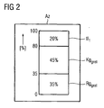
- FIG. 2 in which an indication Az of the load distribution of the automation system 1 is shown, wherein the percentage determined weighted total relative communication load Kg grel , the determined weighted total relative load Rg grel and the idle time tl 1 of the most heavily used processing unit V 1 are displayed.
- the load distribution of an automation system has been determined, which has an automation device and a peripheral device, which are each provided with a processing unit.
- the method according to the invention can also be applied to an automation device provided with a plurality of processing or CPU units and / or to a peripheral device provided with a plurality of processing or CPU units.
- the term "automation system" for the overall context of this description is to be interpreted as comprising all devices, devices or systems, ie in addition to z.
- controllers such as programmable logic controllers, process computers, (industrial) computers and the like, also drive controls, frequency converters and the like, as they are used to control, regulation and / or monitoring of technical processes z.
- B. for forming or transporting material, energy or information, etc. are used or can be used, in particular via suitable technical equipment such.
- sensors or actuators energy is spent or converted.
Landscapes
- Engineering & Computer Science (AREA)
- Physics & Mathematics (AREA)
- General Physics & Mathematics (AREA)
- Software Systems (AREA)
- Theoretical Computer Science (AREA)
- Automation & Control Theory (AREA)
- General Engineering & Computer Science (AREA)
- Debugging And Monitoring (AREA)
Description
- Die Erfindung betrifft ein Verfahren zur Ermittlung der Lastverteilung eines Automatisierungssystems, welches mit einer Anzahl von Verarbeitungseinheiten versehen ist, auf denen Programmteile zur Steuerung eines technischen Prozesses ablaufen.
- Aus dem "Siemens-Katalog ST 70", Ausgabe 2009 sind unterschiedlich ausgebildete Automatisierungsgeräte bekannt, welche zur Lösung kleiner, mittlerer und größerer Automatisierungsaufgaben vorgesehen sind, wobei zur Lösung kleiner Automatisierungsaufgaben mikro-speicherprogrammierbare Steuerungen, zur Lösung mittlerer Automatisierungsaufgaben speicherprogrammierbare Kleinsteuerungen und zur Lösung komplexerer Automatisierungsaufgaben leistungsstarke speicherprogrammierbare Steuerungen einsetzbar sind. In vielen Fällen werden eine Vielzahl von Automatisierungsgeräten oder -systemen miteinander vernetzt, wobei erst diese vernetzten Systeme überhaupt einen reibungslosen Betrieb von komplexen Anlagen ermöglichen. Insbesondere aufgrund dieser Vernetzung ist es erforderlich, dass ein Automatisierungssystem neben Steuerungsfunktionen auch Kommunikationsfunktionen verwirklicht. Darüber hinaus gibt es Anforderungen von überlagerten Beobachtungsebenen und Leitwarten an die Diagnosefunktionen und Auskunftsfunktionen eines Automatisierungssystems. Dies bedeutet, dass ein Automatisierungssystem überlastet sein kann, ohne dass dies für einen Anwender oder Anlagenbetreiber unmittelbar ersichtlich ist. Hinweise für eine derartige Überlastung ergeben sich gewöhnlich nur aufgrund zu langer Reaktionszeiten oder aufgrund von Telegrammverlusten.
- Aus der
EP 1 598 715 A1 ist ein Verfahren zur Ermittlung der Kommunikationslast eines Automatisierungssystems bekannt. Einer Systemeinheit eines Automatisierungssystems wird dazu ein Kontrollraum zugeordnet, wobei sowohl in diesen Kontrollraum eintretende als auch aus diesem austretende Kommunikationsereignisse erfasst werden. Hinweise auf eine Auslastung bzw. auf eine Lastverteilung eines vernetzten Automatisierungssystems, welches mehrere Verarbeitungseinheiten aufweist, sind aus derEP 1 598 715 A1 nicht zu entnehmen. - Dokument "Messung und Bewertung sequentieller und paralleler Programme", Alexander Buck, Universität Tübingen, 17. Juli 1999, beschreibt den Bezug eines Mehrprozessorsystems zu einem Einprozessorssystem, wobei Maßnahmen gezeigt werden, die Höhe des "Speedups" des Mehrprozessorsystems zu ermitteln.
-
EP 1 505 462 A2 offenbart ein Automatisierungsgerät, wobei Maßnahmen zur Verbesserung der Ausführung von Ablaufprogrammen auf diesem Automatisierungsgerät vorgesehen sind. - Der vorliegenden Erfindung liegt die Aufgabe zugrunde, ein Verfahren der eingangs genannten Art anzugeben, mittels dessen die Auslastung bzw. Lastverteilung eines mehrere Verarbeitungseinheiten aufweisenden Automatisierungssystems ermöglicht wird.
- Diese Aufgabe wird durch die im kennzeichnenden Teil des Anspruchs 1 angegebenen Maßnahmen gelöst.
- Vorteilhaft ist, dass neben der Kommunikationslast und der Restlast für jede der Verarbeitungseinheiten des Automatisierungssystems auch die Gesamt-Kommunikations- und Gesamt-Restlast ermittelt werden, welche einem Anwender angezeigt werden können, wobei die Lastverteilung auf der Erfassung bzw. Messung der Laufzeiten der ersten, zweiten und dritten Programmteile sowie der Leerläufe basiert. Dabei werden die Laufzeiten der Programmteile einer Verarbeitungseinheit umgekehrt proportional gewichtet mit der Leerlaufzeit, wodurch die Laufzeiten der höher belasteten Verarbeitungseinheit stärker gewichtet sind.
- Die ersten Programmteile verwirklichen Kommunikationsfunktionen - sind also zur Bearbeitung von Kommunikationsaufgaben vorgesehen -, die zweiten verwirklichen Restfunktionen und die dritten sowohl Kommunikations- als auch Restfunktionen. Als eine Restfunktion wird z. B. die Bearbeitung von Steuerungsaufgaben angesehen. Unter Programmteilen werden sowohl Tasks, Threads und/oder sonstige geeignete (Anwender)-Programme bzw. Software-Bausteine zur Verwirklichung einer Funktion des Automatisierungssystems verstanden.
- In einer Ausgestaltung der Erfindung gemäß den im Anspruch 2 angegebenen Maßnahmen werden eine relative Gesamt-Kommunikationslast und eine relative Gesamt-Restlast des Automatisierungssystems auf einer Anzeigeeinheit dargestellt, wodurch einem Anwender übersichtlich die Lastverteilung des Automatisierungssystems angezeigt wird. Dabei "orientiert" sich die ermittelte gewichtete relative Gesamt-Kommunikationslast und die gewichtete relative Gesamt-Restlast an der stärksten belasteten bzw. ausgelasteten Verarbeitungseinheit.
- Anhand der Zeichnung, in der ein Ausführungsbeispiel der Erfindung veranschaulicht ist, werden im Folgenden die Erfindung, deren Ausgestaltungen sowie Vorteile näher erläutert.
- Es zeigen:
-
Figur 1 Bestandteile eines Automatisierungssystems und -
Figur 2 eine Anzeige einer Lastverteilung. - In
Figur 1 sind mit 1 Teile eines Automatisierungssystems bezeichnet, welches ein Automatisierungsgerät 2, ein dezentrales Peripheriegerät 3 und mehrere Feldgeräte 4, 5, 6 aufweist. Das Automatisierungsgerät 2 sowie das dezentrale Peripheriegerät 3 weisen jeweils eine Verarbeitungseinheit sowie weitere Einheiten bzw. Baugruppen auf, z. B. Baugruppen in Form von Regler- und/oder Ein-/Ausgabe- und/oder sonstigen Funktions-Baugruppen, wobei die Einheiten bzw. Baugruppen über einen hier nicht dargestellten Rückwandbus miteinander verbunden sind. Selbstverständlich kann das Automatisierungssystem 1 je nach einer zu lösenden Steuerungsaufgabe mit weiteren Automatisierungsgeräten und/oder dezentralen Peripheriegeräten versehen sein. Darüber hinaus sind gewöhnlich das Automatisierungsgerät 2 sowie Systeme in Form eines Engineeringsystems, eines Bedien- und Beobachtungssystems, eines Asset-Management-Systems und/oder Servern an einen hier nicht dargestellten Bus angeschlossen. Das Automatisierungsgerät 2 ist über einen für hohe Kommunikationsgeschwindigkeiten ausgelegten Feldbus 7, z. B. in Form eines an sich bekannten Feldbusses "PROFIBUS DP", mit dem dezentralen Peripheriegerät 3 verbunden. Mit jeweils weiteren für die Prozessautomatisierung geeigneten Kommunikationsverbindungen sind die Feldgeräte 4, 5, 6 an ein Interface-Modul 11 des dezentralen Peripheriegerätes 3 angeschlossen. - Im Folgenden wird angenommen, dass lediglich eine Lastverteilung der mit V1, V2 bezeichneten Verarbeitungseinheiten des Automatisierungs- und des Peripheriegerätes 2, 3 ermittelt wird und dass diese Verarbeitungseinheiten erste, zweite und dritte Programmteile verarbeiten. Die ersten Programmteile verwirklichen im Wesentlichen Kommunikationsfunktionen, was bedeutet, dass diese Teile unmittelbar Kommunikationsfunktionen zuzuordnen sind. Die zweiten Programmteile verwirklichen sonstige Funktionen bzw. Restfunktionen, was bedeutet, diese Teile sind von Kommunikationsfunktionen vollständig unabhängig. Die dritten Programmteile verwirklichen sowohl Kommunikations- als auch Restfunktionen; diese Teile können also nicht eindeutig dem ersten oder zweiten Programmteil zugeordnet werden und stellen deshalb einen eigenen Programmteil dar.
- Ferner wird angenommen, dass jeweils eine Task der Verarbeitungseinheiten V1, V2 während eines Beobachtungs-Zeitintervalls T die Laufzeiten der ersten, zweiten und dritten Programmteile sowie die Leerlaufzeit dieser jeweiligen Verarbeitungseinheiten V1, V2 misst. Die Task der Verarbeitungseinheit V2 übermittelt die gemessenen Werte der Verarbeitungseinheit V1, welche die Lastverteilung des Automatisierungssystems 1 - wie im Folgenden gezeigt wird - ermittelt. Selbstverständlich kann die Verarbeitungseinheit V2 oder eine sonstige Verarbeitungseinheit, z. B. eine Verarbeitungseinheit einer an das Automatisierungssystem 1 angeschlossenen Maintenance- bzw. Asset-Management-Station, die Lastverteilung des Automatisierungssystems 1 ermitteln, wobei in diesem Fall der Verarbeitungseinheit V2 oder dieser sonstigen Verarbeitungseinheit die Laufzeiten zu übermitteln sind.
- Folgende Annahmen liegen im vorliegenden Ausführungsbeispiel für die Berechnung der Lastverteilung bzw. der Auslastung zugrunde:
- Während des Beobachtungs-Zeitintervalls T wird für die Verarbeitungseinheit V1 gemessen:
- Laufzeit tk1 von ersten Programmteilen = 0,3T;
- Laufzeit ts1 von zweiten Programmteilen = 0, 3T;
- Laufzeit tks1 von dritten Programmteilen = 0,2T;
- Leerlaufzeit tl1 = 0,2T.
- Für die Verarbeitungseinheit V2 wird während des Beobachtungs-Zeitintervalls T gemessen:
- Laufzeit tk2 von ersten Programmteilen = 0,4T;
- Laufzeit ts2 von zweiten Programmteilen = 0, 2T;
- Laufzeit tks2 von dritten Programmteilen = 0,1T;
- Leerlaufzeit tl2 = 0,3T.
- Mittels der gemessenen Laufzeiten werden zunächst für jede der Verarbeitungseinheiten V1, V2 die Kommunikationslast-Laufzeit und die Restlast-Laufzeit errechnet, wobei allgemein gilt:
- Kommunikationslast-Laufzeit:

- Restlast-Laufzeit:

- Für die Verarbeitungseinheit V1 ergibt sich daher folgende Kommunikationslast-Laufzeit Klt1:

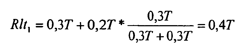
- Die Restlast-Laufzeit der Verarbeitungseinheit V1 ergibt sich daher zu:
- Für die Verarbeitungseinheit V2 ergibt sich eine Kommunikationslast-Laufzeit:

- Die Restlast-Laufzeit der Verarbeitungseinheit V2 ergibt sich zu:

- Die errechneten Kommunikationslast- und die errechneten Restlast-Laufzeiten werden umgekehrt proportional gewichtet mit den Leerlaufzeiten der jeweiligen Verarbeitungseinheit V1, V2, um eine Gesamt-Kommunikationslast Kg und eine Gesamt-Restlast Rg des Automatisierungssystems 1 zu errechnen. Aufgrund der umgekehrt proportionalen Gewichtung wird die stärker belastete Verarbeitungseinheit V1 stärker gewichtet, obwohl die Kommunikationslast-Laufzeit Klt1 geringer ist als die Kommunikationslast-Laufzeit Klt2 der Verarbeitungseinheit V2. Es gilt allgemein:


- Die Gesamt-Kommunikationslast Kg und eine Gesamt-Restlast Rg errechnen sich daher im vorliegenden Beispiel zu:


- Die derart ermittelte Gesamt-Kommunikationslast und Gesamt-Restlast des Automatisierungssystems 1 können einem Anwender auf einer Anzeigeeinheit, z. B. auf einer Anzeigeeinheit der Maintenance- bzw. Asset-Management-Station, angezeigt werden.
- Um eine übersichtlichere Darstellung der Lastverteilung zu ermöglichen, werden in weiteren Verfahrensschritten eine gewichtete relative Gesamt-Kommunikationslast Kggrel und eine gewichtete relative Gesamt-Restlast Rggrel ermittelt. Dazu werden zunächst eine auf eine Gesamtauslastung Ga=Kg+Rg bezogene relative Gesamt-Kommunikationslast Kgrel sowie eine auf diese Gesamtauslastung Ga bezogene relative Gesamt-Restlast Rgrel errechnet, wobei allgemein gilt:

und
- Die relative Gesamt-Kommunikationslast Kgrel errechnet sich im vorliegenden Beispiel zu:

und die relative Gesamt-Restlast Rgrel zu:
- In einem weiteren Schritt wird zur Bestimmung der gewichteten relativen Gesamt-Kommunikationslast Kggrel und der gewichteten relativen Gesamt-Restlast Rggrel ein Lastfaktor Lf der am stärksten belasteten Verarbeitungseinheit V1, V2 bestimmt. Im vorliegenden Beispiel ist die am stärksten ausgelastete Verarbeitungseinheit die Verarbeitungseinheit V1, deren Leerlaufzeit - wie angenommen - 0,2T ist, d. h., die Verarbeitungseinheit V1 ist zu 80% ausgelastet, was bedeutet, dass der Lastfaktor Lf=0,8 ist. Im Unterschied dazu ist die Verarbeitungseinheit V2 lediglich zu 70% ausgelastet (Leerlaufzeit 0,3T). Eine derart ermittelte gewichtete relative Gesamt-Kommunikationslast Kggrel und gewichtete relative Gesamt-Restlast Rggrel ,,orientiert" sich also an der stärksten belasteten bzw. ausgelasteten Verarbeitungseinheit. Mittels dieses Lastfaktors Lf wird die gewichtete relative Gesamt-Kommunikationslast Kggrel und die gewichtete relative Gesamt-Restlast Rggrel errechnet zu:

und
- Diese relative Gesamt-Kommunikationslast Kgrel und diese relative Gesamt-Restlast Rgrel des Automatisierungssystems 1 sind auf einer Anzeigeeinheit darstellbar, wodurch einem Anwender übersichtlich die Lastverteilung des Automatisierungssystems 1 angezeigt wird.
- In diesem Zusammenhang wird auf
Figur 2 verwiesen, in welcher eine Anzeige Az der Lastverteilung des Automatisierungssystems 1 dargestellt ist, wobei prozentual die ermittelte gewichtete relative Gesamt-Kommunikationslast Kggrel, die ermittelte gewichtete relative Gesamt-Restlast Rggrel und die Leerlaufzeit tl1 der am stärksten ausgelasteten Verarbeitungseinheit V1 angezeigt sind. Auf die gewichtete relative Gesamt-Kommunikationslast Kggrel entfallen 45%, auf die gewichtete relative Gesamt-Restlast Rggrel 35% und auf den Leerlauf 20% der Belastung des Automatisierungssystems 1. - Im vorliegenden Ausführungsbeispiel wurde die Lastverteilung eines Automatisierungssystems ermittelt, welches ein Automatisierungsgerät und ein Peripheriegerät aufweist, die jeweils mit einer Verarbeitungseinheit versehen sind. Selbstverständlich ist das erfindungsgemäße Verfahren auch auf ein mit mehreren Verarbeitungs- bzw. CPU-Einheiten versehenes Automatisierungsgerät und/oder auf ein mit mehreren Verarbeitungs- bzw. CPU-Einheiten versehenes Peripheriegerät anwendbar. Allgemein ist der Begriff "Automatisierungssystem" für den Gesamtzusammenhang dieser Beschreibung so auszulegen, dass er sämtliche Geräte, Einrichtungen oder Systeme umfasst, also neben z. B. Steuerungen, wie speicherprogrammierbaren Steuerungen, Prozessrechnern, (Industrie-)Computern und dergleichen, auch Antriebssteuerungen, Frequenzumrichter und Ähnliches, wie sie zur Steuerung, Regelung und/oder Überwachung technischer Prozesse z. B. zum Umformen oder Transportieren von Material, Energie oder Information etc. eingesetzt werden oder einsetzbar sind, wobei insbesondere über geeignete technische Einrichtungen, wie z. B. Sensoren oder Aktoren, Energie aufgewandt oder gewandelt wird.
Claims (3)
- Verfahren zur Ermittlung der Lastverteilung eines Automatisierungssystems, welches mit einer Anzahl von Verarbeitungseinheiten Vi, i=1, 2, ... versehen ist, auf denen Programmteile zur Steuerung eines technischen Prozesses ablaufen, gekennzeichnet durch folgende Verfahrensschritte:- während eines Zeitintervalls T werden für jede der Verarbeitungseinheiten Vi, i=1, 2, ... eine Leerlaufzeit tli, i=1, 2, ..., eine erste Laufzeit tki, i=1, 2, ... von ersten, eine zweite Laufzeit tsi, i=1, 2, ... von zweiten und eine dritte Laufzeit tksi, i=1, 2, ... von dritten Programmteilen erfasst, wobei die ersten Programmteile Kommunikationsfunktionen, die zweiten Restfunktionen und die dritten sowohl Kommunikations- als auch Restfunktionen verwirklichen,- für jede Verarbeitungseinheit Vi, i=1, 2, ... wird eine Kommunikationslast-Laufzeit Klti ermittelt gemäß der Beziehung:
 - für jede Verarbeitungseinheit Vi, i=1, 2, ... wird eine Restlast-Laufzeit Rlti ermittelt gemäß der Beziehung:
 - für das Automatisierungssystem wird die Gesamt-Kommunikationslast Kg ermittelt gemäß der Beziehung:
 - für das Automatisierungssystem wird die Gesamt-Restlast Rg ermittelt gemäß der Beziehung:
- Verfahren nach Anspruch 1, gekennzeichnet durch die weiteren Verfahrensschritte:- Ermitteln einer relativen Gesamt-Kommunikationslast Kgrel gemäß der Beziehung:
 - Ermitteln einer relativen Gesamt-Restlast Rgrel gemäß der Beziehung:
 - Ermitteln eines Lastfaktors Lf der am stärksten ausgelasteten Verarbeitungseinheit Vi, i=1, 2, ... aus den erfassten Leerlaufzeiten tli, i=1, 2, ... oder aus der Summe der Laufzeiten tki, tsi, tksi, i=1, 2, ... der ersten, zweiten und dritten Programmteile (Pk, Ps, Pks) der Verarbeitungseinheiten Vi, i=1, 2, ...,- Ermitteln einer gewichteten relativen Gesamt-Kommunikationslast Kggrel gemäß der Beziehung:
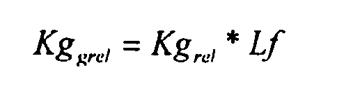 - Ermitteln einer gewichteten relativen Gesamt-Restlast Rggrel gemäß der Beziehung:
- Verfahren nach Anspruch 2, dadurch gekennzeichnet, dass die gewichtete relative Gesamt-Kommunikationslast Kggrel und die gewichtete relative Gesamt-Restlast Rggrel auf einer Anzeigeeinheit angezeigt werden.
Priority Applications (1)
| Application Number | Priority Date | Filing Date | Title |
|---|---|---|---|
| EP20100002234 EP2363769B1 (de) | 2010-03-04 | 2010-03-04 | Verfahren zur Ermittlung der Lastverteilung eines Automatisierungssystems |
Applications Claiming Priority (1)
| Application Number | Priority Date | Filing Date | Title |
|---|---|---|---|
| EP20100002234 EP2363769B1 (de) | 2010-03-04 | 2010-03-04 | Verfahren zur Ermittlung der Lastverteilung eines Automatisierungssystems |
Publications (2)
| Publication Number | Publication Date |
|---|---|
| EP2363769A1 EP2363769A1 (de) | 2011-09-07 |
| EP2363769B1 true EP2363769B1 (de) | 2012-12-12 |
Family
ID=42357281
Family Applications (1)
| Application Number | Title | Priority Date | Filing Date |
|---|---|---|---|
| EP20100002234 Not-in-force EP2363769B1 (de) | 2010-03-04 | 2010-03-04 | Verfahren zur Ermittlung der Lastverteilung eines Automatisierungssystems |
Country Status (1)
| Country | Link |
|---|---|
| EP (1) | EP2363769B1 (de) |
Family Cites Families (3)
| Publication number | Priority date | Publication date | Assignee | Title |
|---|---|---|---|---|
| JP2005056196A (ja) * | 2003-08-05 | 2005-03-03 | Fanuc Ltd | プログラマブルコントローラ |
| EP1598715A1 (de) | 2004-05-18 | 2005-11-23 | Siemens Aktiengesellschaft | Verfahren zur Erfassung der Kommunikationslast eines Automatisierungssystems |
| US7941805B2 (en) * | 2006-08-15 | 2011-05-10 | International Business Machines Corporation | Affinity dispatching load balancer with precise CPU consumption data |
-
2010
- 2010-03-04 EP EP20100002234 patent/EP2363769B1/de not_active Not-in-force
Also Published As
| Publication number | Publication date |
|---|---|
| EP2363769A1 (de) | 2011-09-07 |
Similar Documents
| Publication | Publication Date | Title |
|---|---|---|
| EP2715462B1 (de) | Verfahren zum betreiben eines sicherheitssteuergeräts | |
| EP3101493B1 (de) | System und verfahren zur steuerung und/oder analytik eines industriellen prozesses | |
| DE102016014152A1 (de) | Numerische Steuervorrichtung | |
| DE102020125218A1 (de) | Diagnosegerät | |
| DE102012011584A1 (de) | Ressourcen-Managementsystem fürAutomatisierungsanlagen | |
| DE112012004728T5 (de) | Verfahren, Programm und System zur Simulationsausführung | |
| DE102010010890A1 (de) | Verfahren zum Ersetzen einer bestehenden Leiteinrichtung in einem Automatisierungssystem durch eine neue Leiteinrichtung und dazu ausgebildetes Automatisierungssystem | |
| EP2154606B1 (de) | Erzeugen einer ablauffähigen Konfiguration | |
| DE102020107861A1 (de) | System zur Verwaltung von Werkzeugwechselzeiten | |
| DE102014016180B4 (de) | Verfahren und Einrichtung zur Verwaltung und Konfiguration von Feldgeräten einer Automatisierungsanlage | |
| EP3151072B1 (de) | Verfahren und system zur fehlererkennung und überwachung bei einem elektronisch geregelten oder gesteuerten maschinenteil | |
| EP2574997A1 (de) | Verfahren zur Einstellung eines Betriebszustandes | |
| EP3088976B1 (de) | Verfahren zum betreiben einer automatisierungseinrichtung und automatisierungseinrichtung | |
| EP2128726A1 (de) | Verfahren und Simulator zur Echtzeitberechnung der Zustandsgrössen eines Prozessmodells | |
| DE102019217427A1 (de) | Steuern und/oder Überwachen einer Maschinenanordnung | |
| EP2363769B1 (de) | Verfahren zur Ermittlung der Lastverteilung eines Automatisierungssystems | |
| DE112016003529T5 (de) | Suchsystem | |
| WO2017080793A2 (de) | Verfahren zum betrieb eines mehrkernprozessors | |
| EP3252549B1 (de) | Verfahren zum betreiben einer automatisierungseinrichtung sowie automatisierungseinrichtung | |
| EP4198663A1 (de) | Verfahren zum verteilten berechnen von berechnungsaufgaben | |
| EP2477085A1 (de) | Verfahren und System zur Analyse eines zeitlichen Ablaufverhaltens eines Steuerungsprogramms einer Industriesteuerung | |
| EP1556811A2 (de) | Vorhersage des termintreuegrads in der serienfertigung | |
| DE102006052757A1 (de) | Automatisierungsgerät mit einer Verarbeitungseinheit und Verwendung einer Verarbeitungseinheit in einem Automatisierungsgerät | |
| EP3588849A1 (de) | Verfahren zum quantifizieren der zuverlässigkeit einer steuerfunktion, die durch mehrere unabhängige funktionseinheiten bereitgestellt wird; sowie steuereinrichtung | |
| DE112014003069T5 (de) | Funktionseinheit, Analogeingabeeinheit und programmierbares Steuerungssystem |
Legal Events
| Date | Code | Title | Description |
|---|---|---|---|
| PUAI | Public reference made under article 153(3) epc to a published international application that has entered the european phase |
Free format text: ORIGINAL CODE: 0009012 |
|
| AK | Designated contracting states |
Kind code of ref document: A1 Designated state(s): AT BE BG CH CY CZ DE DK EE ES FI FR GB GR HR HU IE IS IT LI LT LU LV MC MK MT NL NO PL PT RO SE SI SK SM TR |
|
| AX | Request for extension of the european patent |
Extension state: AL BA ME RS |
|
| 17P | Request for examination filed |
Effective date: 20120220 |
|
| GRAP | Despatch of communication of intention to grant a patent |
Free format text: ORIGINAL CODE: EPIDOSNIGR1 |
|
| GRAS | Grant fee paid |
Free format text: ORIGINAL CODE: EPIDOSNIGR3 |
|
| GRAA | (expected) grant |
Free format text: ORIGINAL CODE: 0009210 |
|
| AK | Designated contracting states |
Kind code of ref document: B1 Designated state(s): AT BE BG CH CY CZ DE DK EE ES FI FR GB GR HR HU IE IS IT LI LT LU LV MC MK MT NL NO PL PT RO SE SI SK SM TR |
|
| REG | Reference to a national code |
Ref country code: GB Ref legal event code: FG4D Free format text: NOT ENGLISH |
|
| REG | Reference to a national code |
Ref country code: CH Ref legal event code: EP |
|
| REG | Reference to a national code |
Ref country code: AT Ref legal event code: REF Ref document number: 588594 Country of ref document: AT Kind code of ref document: T Effective date: 20121215 |
|
| REG | Reference to a national code |
Ref country code: IE Ref legal event code: FG4D Free format text: LANGUAGE OF EP DOCUMENT: GERMAN |
|
| REG | Reference to a national code |
Ref country code: DE Ref legal event code: R096 Ref document number: 502010001823 Country of ref document: DE Effective date: 20130207 |
|
| RAP2 | Party data changed (patent owner data changed or rights of a patent transferred) |
Owner name: SIEMENS AKTIENGESELLSCHAFT |
|
| PG25 | Lapsed in a contracting state [announced via postgrant information from national office to epo] |
Ref country code: LT Free format text: LAPSE BECAUSE OF FAILURE TO SUBMIT A TRANSLATION OF THE DESCRIPTION OR TO PAY THE FEE WITHIN THE PRESCRIBED TIME-LIMIT Effective date: 20121212 Ref country code: ES Free format text: LAPSE BECAUSE OF FAILURE TO SUBMIT A TRANSLATION OF THE DESCRIPTION OR TO PAY THE FEE WITHIN THE PRESCRIBED TIME-LIMIT Effective date: 20130323 Ref country code: NO Free format text: LAPSE BECAUSE OF FAILURE TO SUBMIT A TRANSLATION OF THE DESCRIPTION OR TO PAY THE FEE WITHIN THE PRESCRIBED TIME-LIMIT Effective date: 20130312 Ref country code: FI Free format text: LAPSE BECAUSE OF FAILURE TO SUBMIT A TRANSLATION OF THE DESCRIPTION OR TO PAY THE FEE WITHIN THE PRESCRIBED TIME-LIMIT Effective date: 20121212 Ref country code: SE Free format text: LAPSE BECAUSE OF FAILURE TO SUBMIT A TRANSLATION OF THE DESCRIPTION OR TO PAY THE FEE WITHIN THE PRESCRIBED TIME-LIMIT Effective date: 20121212 |
|
| PGFP | Annual fee paid to national office [announced via postgrant information from national office to epo] |
Ref country code: FR Payment date: 20130408 Year of fee payment: 4 |
|
| REG | Reference to a national code |
Ref country code: NL Ref legal event code: VDEP Effective date: 20121212 |
|
| REG | Reference to a national code |
Ref country code: LT Ref legal event code: MG4D |
|
| PG25 | Lapsed in a contracting state [announced via postgrant information from national office to epo] |
Ref country code: SI Free format text: LAPSE BECAUSE OF FAILURE TO SUBMIT A TRANSLATION OF THE DESCRIPTION OR TO PAY THE FEE WITHIN THE PRESCRIBED TIME-LIMIT Effective date: 20121212 Ref country code: LV Free format text: LAPSE BECAUSE OF FAILURE TO SUBMIT A TRANSLATION OF THE DESCRIPTION OR TO PAY THE FEE WITHIN THE PRESCRIBED TIME-LIMIT Effective date: 20121212 Ref country code: GR Free format text: LAPSE BECAUSE OF FAILURE TO SUBMIT A TRANSLATION OF THE DESCRIPTION OR TO PAY THE FEE WITHIN THE PRESCRIBED TIME-LIMIT Effective date: 20130313 |
|
| PG25 | Lapsed in a contracting state [announced via postgrant information from national office to epo] |
Ref country code: IS Free format text: LAPSE BECAUSE OF FAILURE TO SUBMIT A TRANSLATION OF THE DESCRIPTION OR TO PAY THE FEE WITHIN THE PRESCRIBED TIME-LIMIT Effective date: 20130412 Ref country code: BG Free format text: LAPSE BECAUSE OF FAILURE TO SUBMIT A TRANSLATION OF THE DESCRIPTION OR TO PAY THE FEE WITHIN THE PRESCRIBED TIME-LIMIT Effective date: 20130312 Ref country code: EE Free format text: LAPSE BECAUSE OF FAILURE TO SUBMIT A TRANSLATION OF THE DESCRIPTION OR TO PAY THE FEE WITHIN THE PRESCRIBED TIME-LIMIT Effective date: 20121212 Ref country code: CZ Free format text: LAPSE BECAUSE OF FAILURE TO SUBMIT A TRANSLATION OF THE DESCRIPTION OR TO PAY THE FEE WITHIN THE PRESCRIBED TIME-LIMIT Effective date: 20121212 Ref country code: SK Free format text: LAPSE BECAUSE OF FAILURE TO SUBMIT A TRANSLATION OF THE DESCRIPTION OR TO PAY THE FEE WITHIN THE PRESCRIBED TIME-LIMIT Effective date: 20121212 |
|
| PG25 | Lapsed in a contracting state [announced via postgrant information from national office to epo] |
Ref country code: RO Free format text: LAPSE BECAUSE OF FAILURE TO SUBMIT A TRANSLATION OF THE DESCRIPTION OR TO PAY THE FEE WITHIN THE PRESCRIBED TIME-LIMIT Effective date: 20121212 Ref country code: NL Free format text: LAPSE BECAUSE OF FAILURE TO SUBMIT A TRANSLATION OF THE DESCRIPTION OR TO PAY THE FEE WITHIN THE PRESCRIBED TIME-LIMIT Effective date: 20121212 Ref country code: PL Free format text: LAPSE BECAUSE OF FAILURE TO SUBMIT A TRANSLATION OF THE DESCRIPTION OR TO PAY THE FEE WITHIN THE PRESCRIBED TIME-LIMIT Effective date: 20121212 Ref country code: PT Free format text: LAPSE BECAUSE OF FAILURE TO SUBMIT A TRANSLATION OF THE DESCRIPTION OR TO PAY THE FEE WITHIN THE PRESCRIBED TIME-LIMIT Effective date: 20130412 |
|
| PGFP | Annual fee paid to national office [announced via postgrant information from national office to epo] |
Ref country code: IT Payment date: 20130331 Year of fee payment: 4 |
|
| BERE | Be: lapsed |
Owner name: SIEMENS A.G. Effective date: 20130331 |
|
| PLBE | No opposition filed within time limit |
Free format text: ORIGINAL CODE: 0009261 |
|
| STAA | Information on the status of an ep patent application or granted ep patent |
Free format text: STATUS: NO OPPOSITION FILED WITHIN TIME LIMIT |
|
| PG25 | Lapsed in a contracting state [announced via postgrant information from national office to epo] |
Ref country code: MC Free format text: LAPSE BECAUSE OF NON-PAYMENT OF DUE FEES Effective date: 20130331 Ref country code: DK Free format text: LAPSE BECAUSE OF FAILURE TO SUBMIT A TRANSLATION OF THE DESCRIPTION OR TO PAY THE FEE WITHIN THE PRESCRIBED TIME-LIMIT Effective date: 20121212 |
|
| 26N | No opposition filed |
Effective date: 20130913 |
|
| PG25 | Lapsed in a contracting state [announced via postgrant information from national office to epo] |
Ref country code: HR Free format text: LAPSE BECAUSE OF FAILURE TO SUBMIT A TRANSLATION OF THE DESCRIPTION OR TO PAY THE FEE WITHIN THE PRESCRIBED TIME-LIMIT Effective date: 20121212 Ref country code: CY Free format text: LAPSE BECAUSE OF FAILURE TO SUBMIT A TRANSLATION OF THE DESCRIPTION OR TO PAY THE FEE WITHIN THE PRESCRIBED TIME-LIMIT Effective date: 20121212 |
|
| REG | Reference to a national code |
Ref country code: IE Ref legal event code: MM4A |
|
| REG | Reference to a national code |
Ref country code: DE Ref legal event code: R097 Ref document number: 502010001823 Country of ref document: DE Effective date: 20130913 |
|
| PG25 | Lapsed in a contracting state [announced via postgrant information from national office to epo] |
Ref country code: IE Free format text: LAPSE BECAUSE OF NON-PAYMENT OF DUE FEES Effective date: 20130304 Ref country code: BE Free format text: LAPSE BECAUSE OF NON-PAYMENT OF DUE FEES Effective date: 20130331 |
|
| PG25 | Lapsed in a contracting state [announced via postgrant information from national office to epo] |
Ref country code: MT Free format text: LAPSE BECAUSE OF FAILURE TO SUBMIT A TRANSLATION OF THE DESCRIPTION OR TO PAY THE FEE WITHIN THE PRESCRIBED TIME-LIMIT Effective date: 20121212 |
|
| PGFP | Annual fee paid to national office [announced via postgrant information from national office to epo] |
Ref country code: DE Payment date: 20130521 Year of fee payment: 4 |
|
| REG | Reference to a national code |
Ref country code: DE Ref legal event code: R119 Ref document number: 502010001823 Country of ref document: DE |
|
| REG | Reference to a national code |
Ref country code: CH Ref legal event code: PL |
|
| GBPC | Gb: european patent ceased through non-payment of renewal fee |
Effective date: 20140304 |
|
| REG | Reference to a national code |
Ref country code: FR Ref legal event code: ST Effective date: 20141128 |
|
| REG | Reference to a national code |
Ref country code: DE Ref legal event code: R119 Ref document number: 502010001823 Country of ref document: DE Effective date: 20141001 |
|
| PG25 | Lapsed in a contracting state [announced via postgrant information from national office to epo] |
Ref country code: GB Free format text: LAPSE BECAUSE OF NON-PAYMENT OF DUE FEES Effective date: 20140304 Ref country code: FR Free format text: LAPSE BECAUSE OF NON-PAYMENT OF DUE FEES Effective date: 20140331 Ref country code: DE Free format text: LAPSE BECAUSE OF NON-PAYMENT OF DUE FEES Effective date: 20141001 Ref country code: CH Free format text: LAPSE BECAUSE OF NON-PAYMENT OF DUE FEES Effective date: 20140331 Ref country code: LI Free format text: LAPSE BECAUSE OF NON-PAYMENT OF DUE FEES Effective date: 20140331 |
|
| PG25 | Lapsed in a contracting state [announced via postgrant information from national office to epo] |
Ref country code: IT Free format text: LAPSE BECAUSE OF NON-PAYMENT OF DUE FEES Effective date: 20140304 |
|
| PG25 | Lapsed in a contracting state [announced via postgrant information from national office to epo] |
Ref country code: SM Free format text: LAPSE BECAUSE OF FAILURE TO SUBMIT A TRANSLATION OF THE DESCRIPTION OR TO PAY THE FEE WITHIN THE PRESCRIBED TIME-LIMIT Effective date: 20121212 |
|
| PG25 | Lapsed in a contracting state [announced via postgrant information from national office to epo] |
Ref country code: TR Free format text: LAPSE BECAUSE OF FAILURE TO SUBMIT A TRANSLATION OF THE DESCRIPTION OR TO PAY THE FEE WITHIN THE PRESCRIBED TIME-LIMIT Effective date: 20121212 |
|
| PG25 | Lapsed in a contracting state [announced via postgrant information from national office to epo] |
Ref country code: MK Free format text: LAPSE BECAUSE OF FAILURE TO SUBMIT A TRANSLATION OF THE DESCRIPTION OR TO PAY THE FEE WITHIN THE PRESCRIBED TIME-LIMIT Effective date: 20121212 Ref country code: LU Free format text: LAPSE BECAUSE OF NON-PAYMENT OF DUE FEES Effective date: 20130304 Ref country code: HU Free format text: LAPSE BECAUSE OF FAILURE TO SUBMIT A TRANSLATION OF THE DESCRIPTION OR TO PAY THE FEE WITHIN THE PRESCRIBED TIME-LIMIT; INVALID AB INITIO Effective date: 20100304 |
|
| REG | Reference to a national code |
Ref country code: AT Ref legal event code: MM01 Ref document number: 588594 Country of ref document: AT Kind code of ref document: T Effective date: 20150304 |
|
| PG25 | Lapsed in a contracting state [announced via postgrant information from national office to epo] |
Ref country code: AT Free format text: LAPSE BECAUSE OF NON-PAYMENT OF DUE FEES Effective date: 20150304 |