EP2363826A2 - Lecteur et procédé de contrôle d'un interrogateur - Google Patents
Lecteur et procédé de contrôle d'un interrogateur Download PDFInfo
- Publication number
- EP2363826A2 EP2363826A2 EP11156621A EP11156621A EP2363826A2 EP 2363826 A2 EP2363826 A2 EP 2363826A2 EP 11156621 A EP11156621 A EP 11156621A EP 11156621 A EP11156621 A EP 11156621A EP 2363826 A2 EP2363826 A2 EP 2363826A2
- Authority
- EP
- European Patent Office
- Prior art keywords
- identifier
- interrogator
- wireless tag
- wireless
- tag
- Prior art date
- Legal status (The legal status is an assumption and is not a legal conclusion. Google has not performed a legal analysis and makes no representation as to the accuracy of the status listed.)
- Withdrawn
Links
Images


Classifications
-
- G—PHYSICS
- G06—COMPUTING OR CALCULATING; COUNTING
- G06K—GRAPHICAL DATA READING; PRESENTATION OF DATA; RECORD CARRIERS; HANDLING RECORD CARRIERS
- G06K7/00—Methods or arrangements for sensing record carriers, e.g. for reading patterns
- G06K7/0008—General problems related to the reading of electronic memory record carriers, independent of its reading method, e.g. power transfer
-
- G—PHYSICS
- G06—COMPUTING OR CALCULATING; COUNTING
- G06K—GRAPHICAL DATA READING; PRESENTATION OF DATA; RECORD CARRIERS; HANDLING RECORD CARRIERS
- G06K19/00—Record carriers for use with machines and with at least a part designed to carry digital markings
- G06K19/06—Record carriers for use with machines and with at least a part designed to carry digital markings characterised by the kind of the digital marking, e.g. shape, nature, code
- G06K19/067—Record carriers with conductive marks, printed circuits or semiconductor circuit elements, e.g. credit or identity cards also with resonating or responding marks without active components
- G06K19/07—Record carriers with conductive marks, printed circuits or semiconductor circuit elements, e.g. credit or identity cards also with resonating or responding marks without active components with integrated circuit chips
- G06K19/0723—Record carriers with conductive marks, printed circuits or semiconductor circuit elements, e.g. credit or identity cards also with resonating or responding marks without active components with integrated circuit chips the record carrier comprising an arrangement for non-contact communication, e.g. wireless communication circuits on transponder cards, non-contact smart cards or RFIDs
Definitions
- the present invention relates to an interrogator capable of inquiring tag identification information to an RFID (Radio Frequency Identification) tag or a wireless tag called a transponder by wireless communication and performing predetermined processing on the wireless tag responding in regard to the tag identification information.
- RFID Radio Frequency Identification
- an interrogator which has an antenna and is capable of reading data from a memory installed in a wireless tag and writing data into the memory by executing wireless communication with the wireless tag present within a communication area by using a radio wave, was developed and put into practical use.
- the memory of each wireless tag stores a unique ID (tag identification information). Therefore, it is possible to specify each wireless tag by reading the ID of the wireless tag through the interrogator.
- the interrogator When data is written into the wireless tag by such a type of interrogator, the interrogator first transmits an inquiry radio wave without specifying a wireless tag. The wireless tag receiving this inquiry radio wave transmits a response radio wave. The response radio wave is modulated with the ID stored in the memory of the wireless tag. The interrogator detects the ID of the wireless tag by demodulating the response radio wave when the interrogator receives the response radio wave from the wireless tag. Thereafter, the interrogator executes one-to-one wireless communication with the wireless tag having this ID and transmits a data writing command. Thus, desired data is written into the memory of the wireless tag.
- an interrogator which detects a reception sensitivity when receiving tag identification information responded from the wireless tag, determining whether the reception sensitivity is equal to or larger than a threshold value, sets the wireless tag determined that the reception sensitivity is equal to or larger than the threshold value as the communication target wireless tag, and performs predetermined processing with only the wireless tag.
- the wireless tags manufactured by the companies have different activation powers or response powers of the IC chips.
- an old model and an improved model may have different activation powers or response powers. Therefore, under the situation where there are plural types of wireless tags, the reception sensitivity is equal to or larger than the threshold value even for a wireless tag distant from the antenna of the interrogator when the interrogator receives the tag identification information. Therefore, predetermined processing may be performed.
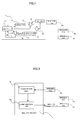
- Fig. 1 is a schematic block diagram illustrating an interrogator and a wireless tag.
- An arrow shown in Fig. 1 indicates a flow direction of a signal.
- An interrogator 1 includes a controller 11, a modulator 12, a high-frequency variable amplifier 13, a circulator 14, an antenna 15, a demodulator 16, an LPF 17, and a variable amplifier 18.
- the controller 11 includes a CPU and a storage unit (neither of which is shown) and controls the interrogator 1 according to a program stored in the storage unit.
- the controller 11 controls transmission processing and reception processing and communicates with an upper-level apparatus such as a PC (not shown).
- the modulator 12 modulates transmission information output from the controller 11, synthesizes the transmission information with a carrier wave to generate a high-frequency signal, and outputs the high-frequency signal.
- the modulator 12 sometimes outputs only the carrier wave when there is no transmission information.
- the high-frequency variable amplifier 13 amplifies input high frequency and outputs the amplified high frequency.
- the controller 11 controls an amplification ratio via a control line 19. A transmission power to be output is changed by changing the amplification ratio.
- the circulator 14 delivers a signal from the high-frequency variable amplifier 13 to the antenna 15 and delivers the signal received by the antenna 15 to the demodulator 16.
- the antenna 15 emits the high-frequency signal from the circulator 14 as a radio wave toward a space and outputs the radio wave from the space as the high-frequency signal to the circulator 14.
- the antenna 15 has a property of strongly emitting a radio wave in a specific direction.
- the antenna 15 may be a plane patch antenna.
- the demodulator 16 demodulates the input high-frequency signal, converts the high-frequency signal into a received data signal, and outputs the received data signal.
- the LPF (Low Pass Filter) 17 removes a high-frequency component included in the received data signal output from the demodulator 16 and outputs only the received data signal.
- the variable amplifier 18 amplifies and outputs the input received data signal.
- the controller 11 controls the amplification ratio via a control line 20. When an intensity level of the received data signal is small, the controller 11 increases the amplification ratio. When the intensity level of the received data signal is large, the controller 11 decreases the amplification ratio. The intensity level of the received data signal can be known from the set amplification ratio.
- a given patent document discloses a unit having a function of automatically controlling the amplification ratio as an AGC (Automatic Gain Control) circuit.
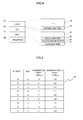
- Fig. 2 is a block diagram illustrating an example of the interrogator according to the embodiment.
- the interrogator 1 includes an acquisition unit 51 and a communication unit 52.
- the acquisition unit 51 acquires an identifier to specify a type of wireless tag stored in the wireless tag.
- the communication unit 52 executes wireless communication based on a communication command at the transmission power according to the identifier acquired by the acquisition unit 51.
- the acquisition unit 51 may be realized by cooperation of the antenna 15, the circulator 14, the demodulator 16, the LPF 17, the variable amplifier 18, and the controller 11.
- the communication unit 52 may be realized by cooperation of the controller 11, the modulator 12, the high-frequency variable amplifier 13, the circulator 14, and the antenna 15.
- Wireless tags 2a, 2b, and 2c each include an antenna and an IC chip.
- the IC chip is an electronic circuit component which includes a power generation unit, a demodulation unit, a modulation unit, a storage unit, and a control unit controlling them.
- the storage unit stores different identification information in each wireless tag. The wireless tag is specified based on the identification information.
- the wireless tag 2a Since the wireless tag 2a is located in a region near the antenna 15 of the interrogator 1, the wireless tag 2a receives a radio wave having a power larger than that of the wireless tags 2b and 2c.
- the wireless tags 2a, 2b, and 2c are different only in the identification information and are the same in hardware characteristics or the like, the desired wireless tag 2a is selected by setting the transmission power of the interrogator 1 to be small, operating only the wireless tag 2a, and not operating the wireless tags 2b and 2c.
- Figs. 3A and 3B are schematic diagrams illustrating the wireless tag.
- the wireless tags 2a to 2c are expressed as the wireless tags 2 when it is not necessary to particularly distinguish the wireless tags 2a to 2c from each other.
- the wireless tag 2 includes an IC chip 30 and an antenna 31.
- the radio wave transmitted from the interrogator 1 is delivered to the IC chip 30 via the antenna 31 and is subjected to processing corresponding to a signal included in the radio wave received by the IC chip 30.
- the antenna 31 has a property corresponding to a linearly-polarized wave.
- the wireless tag 2 illustrated in Fig. 3A may be modified so as to have the configuration shown in Fig. 3B . That is, the wireless tag 2 shown in Fig. 3B includes an IC chip 32 and an antenna 33 and operates in the same way as that of the wireless tag 2 shown in Fig. 3A .
- the antenna 33 has a property corresponding to a circularly-polarized wave.
- Fig. 4 is a schematic diagram illustrating information stored in the wireless tag 2.
- a memory format of the wireless tag called Class-1 Generation ⁇ 2 (hereinafter, referred to as EPC Gen-2) standardized by EPC global is shown.
- RESERVED 40 stores information used in a communication protocol with the interrogator.
- EPC (Electronic Product Code) 41 stores different identification information in the wireless tags 2a to 2c.
- TID 42 stores an identifier specifying a type of IC chip.
- TID 42 includes a class identifier 44, a tag designer identifier 45, and a model identifier 46.
- the class identifier 44 is defined in ISO/IEC 15963 and stores data corresponding to the protocol used by the wireless tag. Here, "11100010" is allocated in the class identifier of the EPC Gen-2.
- the tag designer identifier 45 is administrated by the registered authorized organization and is acquired by IC chip manufacturers. When the manufacturers are different, the tag designer identifiers are different from each other.
- the model identifier 46 includes a model number of the IC chip defined by the IC chip manufacturer. When models of the IC chips are different, the model identifiers are different from each other.
- TID 42 is stored in a read-only memory and the information written at the time of manufacture may not be rewritten.
- USER 43 includes an antenna identifier 48 and other information 49.
- the antenna identifier 48 stores information corresponding to the shape of the antenna. After information is written into the antenna identifier 48, the memory area may be set as a writing prohibited area.
- the interrogator 1 specifies the type of IC chip of the wireless tag by reading the tag designer identifier 45 and the model identifier 46 of the wireless tag. Alternatively, the type of antenna may be specified from the antenna identifier 48.
- the tag designer identifier 45, the model identifier 46, and the antenna identifier 48 may be used as the "identifier".
- the transmission power of the interrogator 1 will be described as an example in detail.
- a case will be described in which the interrogator 1 communicates with the wireless tag 2 located within a range up to 10 cm from the antenna 15 on the assumption that a gain of the antenna 15 of the interrogator 1 is 3 dBi.
- the wireless tag 2 executing wireless communication has the shape shown in Fig. 3A
- the gain of the antenna 31 is 2 dBi
- a minimum activation power of the IC chip 30 is -10 dBm
- the transmission power of the interrogator 1 is set to 10 dBm.
- a maximum communication distance between the interrogator 1 and the wireless tag 2 becomes about 10 cm.
- the communication target wireless tag 2 is specified by setting the transmission power of the interrogator 1 to be small.
- the wireless tags 2 with different antenna gains are sometimes used due to a restriction on the shape of the antenna in products to which the wireless tags 2 are attached.
- the minimum activation power tends to decrease due to an improvement in the IC chip 30. Accordingly, even when the outer appearances of the wireless tags are the same as each other, the wireless tags 2 with different communication distances are sometimes used.
- the interrogator 1 determines whether the wireless tag 2 is the communication target wireless tag 2 based on the intensity level of the received data signal received from the wireless tag 2.
- the wireless tag 2 transmits information while reflecting the radio wave from the interrogator 1 in a method called backscatter modulation.
- a reflection loss of the wireless tag 2 is 9 dB and a distance between the interrogator 1 and the wireless tag 2 is 10 cm
- the intensity level of the received data signal received by the interrogator 1 becomes -39 dBm.
- the intensity level of the received data signal becomes larger than -39 dBm.
- the interrogator 1 determines that the wireless tag 2 is not the communication target wireless tag 2, when the intensity level of the received data signal is smaller than -39 dBm. That is, a minimum intensity level of the received data signal is a threshold value used to determine the communication target wireless tag 2.
- the wireless tag 2 has the shape shown in Fig. 3B , the gain of the antenna 33 is 0 dBi, and the minimum activation power of the IC chip 32 is -10 dBm, the transmission power of the interrogator 1 is set to 12 dBm. Then, the maximum communication distance between the interrogator 1 and the wireless tag 2 becomes about 10 cm. When the reflection loss of the wireless tag 2 is 8 dB, the minimum intensity level of the received data signal received by the interrogator 1 becomes -43 dBm.
- a relationship between the transmission power of the interrogator and the minimum intensity level of the received data signal is schematically shown in Fig. 5 when three types of IC chips ⁇ , ⁇ , and ⁇ are used and three types of antennas a, b, and c are used.
- the minimum activation powers of the IC chips ⁇ , ⁇ , and ⁇ are -10 dBm, -15 dBm, and -20 dBm, respectively.
- the reflection losses of the IC chips ⁇ , ⁇ , and ⁇ are 9 dB, 8 dB, and 7 dB, respectively.
- the antenna gains of the antennas a, b, and c are 2 dBi, 0 dBi, and -3 dBi, respectively.
- the transmission power of the interrogator 1 and the minimum intensity level of the received data signal are determined using combinations of the IC chips and the antennas of the wireless tags 2, and it is determined whether the wireless tag communicating with the interrogator 1 is the communication target wireless tag.
- the interrogator 1 sets the transmission power used to transmit a query to the wireless tag 2.
- the set transmission power may be set to 15 dBm or more.
- the interrogator 1 transmits an identifier query command.
- the interrogator 1 transmits Query, receives RN 16 from the wireless tag 2, transmits ACK, receives EPC from the wireless tag, and then transmits a Read command to inquire TID 42 and USER 42 to the wireless tag.
- Act 103 it is determined whether a response to the identifier is made. When the response is made, the process proceeds to Act 105. On the other hand, where there is no response, it is determined whether the process ends. When the process does not end, the process returns to Act 102. When the process ends, the flow of the process ends. The process ends in Act 104 under conditions in which the query is transmitted a predetermined number of times or for a predetermined time and there is no wireless tag 2 responding to the query.
- the transmission power is set by controlling the amplification ratio of the high-frequency variable amplifier 13 of the interrogator 1 according to the identifier received in Act 106.
- the value of the set transmission power is determined according to a set value table 50. In this embodiment, the transmission power is set to 15 dBm or less.
- a reading command (communication command) is transmitted.
- the reason for transmitting the reading command is to distinguish a plurality of wireless tags 2 with the same identifier and different distances from the interrogator 1 from each other.
- the reading command is a command used to specify the wireless tag 2 performing writing.
- the reading command may be a command used to read EPC 41 stored in the wireless tag 2.
- a command, such as a Read command which does not change the information stored in the wireless tag 2 is transmitted.
- Act 108 It is determined whether there is a response in Act 108. When there is the response, the process proceeds to Act 110. On the other hand, when there is no response, the process proceeds to Act 109. In Act 109, it is determined whether the reading command is transmitted a predetermined number of times. When the reading command is not transmitted the predetermined number of times, the process returns to Act 107 and the reading command is retransmitted. On the other hand, when the number of times which transmitted the reading command is the predetermined number of times, the process returns to Act 101.
- the wireless tag 2 which does not respond even when the reading command is transmitted by the predetermined number of times in Act 109 is considered not to be the wireless tag 2 which desires to execute the writing process since this wireless tag 2 is located out of the communicable range of the interrogator 1.
- the intensity level of the received data signal is observed while response data is received in Act 110.
- the process proceeds to Act 112.
- the received response has the intensity level smaller than the minimum intensity level, the process returns to Act 101.
- a writing command and writing data are transmitted to the wireless tag 2 and writing is performed.
- a Write command or a BlockWrite command are transmitted.
- the operation of writing the information into the wireless tag is hitherto described. However, the same processing is performed even when the information stored in the wireless tag is changed by an operation of prohibiting information from being written into a storage area of the wireless tag or an operation of setting a password to permit communication with the wireless tag or the like.
- the numerals of dBm unit are used as the intensity of the received data signal.
- values set in the AGC circuit may be used instead of the numerals of dBm unit.
- the transmission power set according to the type of wireless tag may be stored in advance in the wireless tag and the subsequent processing may be performed based on the stored transmission power.
- the subsequent processing is a process after Act 106 of the flowchart shown in Fig. 6 . That is, information in which the transmission powers and the types of wireless tags correspond to each other may be stored in the storage unit of each wireless tag.
- the tag designer identifier 45, the model identifier 46, and the antenna identifiers 48 are used as the identifiers used to distinguish the wireless tags from each other, but other configurations may be used.
- the identifiers used to distinguish the wireless tags from each other may include only the tag designer identifier 45 and the model identifier 46. That is, only the types of IC chips are used as the identification information.
- desired transmission power may be set by storing the types of IC chips, the transmission powers, and the minimum intensity level in correspondence with each other.
Landscapes
- Engineering & Computer Science (AREA)
- Physics & Mathematics (AREA)
- General Physics & Mathematics (AREA)
- Theoretical Computer Science (AREA)
- Artificial Intelligence (AREA)
- Computer Vision & Pattern Recognition (AREA)
- Computer Networks & Wireless Communication (AREA)
- Computer Hardware Design (AREA)
- Microelectronics & Electronic Packaging (AREA)
- Near-Field Transmission Systems (AREA)
Applications Claiming Priority (1)
| Application Number | Priority Date | Filing Date | Title |
|---|---|---|---|
| JP2010047046A JP2011182340A (ja) | 2010-03-03 | 2010-03-03 | 質問器 |
Publications (2)
| Publication Number | Publication Date |
|---|---|
| EP2363826A2 true EP2363826A2 (fr) | 2011-09-07 |
| EP2363826A3 EP2363826A3 (fr) | 2011-09-28 |
Family
ID=44063727
Family Applications (1)
| Application Number | Title | Priority Date | Filing Date |
|---|---|---|---|
| EP11156621A Withdrawn EP2363826A3 (fr) | 2010-03-03 | 2011-03-02 | Lecteur et procédé de contrôle d'un interrogateur |
Country Status (4)
| Country | Link |
|---|---|
| US (1) | US20110215906A1 (fr) |
| EP (1) | EP2363826A3 (fr) |
| JP (1) | JP2011182340A (fr) |
| CN (1) | CN102194138A (fr) |
Cited By (1)
| Publication number | Priority date | Publication date | Assignee | Title |
|---|---|---|---|---|
| EP2840554A1 (fr) * | 2013-08-23 | 2015-02-25 | Kapsch TrafficCom AG | Procédé et capteur radio pour la localisation d'une unité embarquée |
Families Citing this family (7)
| Publication number | Priority date | Publication date | Assignee | Title |
|---|---|---|---|---|
| KR101003017B1 (ko) * | 2009-12-30 | 2010-12-21 | 동아대학교 산학협력단 | MultiㅡSubscription기능을 가진 RFID 시스템 및 이의 운용 방법 |
| JP2014067235A (ja) * | 2012-09-26 | 2014-04-17 | Hitachi Chemical Co Ltd | 積層対応のrfidタグ及びrfidタグシステム |
| JP2016006596A (ja) * | 2014-06-20 | 2016-01-14 | 三菱電機株式会社 | 動態管理システム |
| US10079573B2 (en) * | 2014-09-11 | 2018-09-18 | Cpg Technologies, Llc | Embedding data on a power signal |
| US11075768B2 (en) | 2015-03-27 | 2021-07-27 | Centro De Pesquisas Avancadas Wernher Von Braun | Embedding protected memory access into a RFID authentication process based on a challenge-response mechanism |
| JP6565881B2 (ja) * | 2016-11-30 | 2019-08-28 | 京セラドキュメントソリューションズ株式会社 | 無線タグ通信システム |
| JP7444634B2 (ja) * | 2020-02-25 | 2024-03-06 | 東芝テック株式会社 | タグ読取装置およびタグ読取システム |
Citations (1)
| Publication number | Priority date | Publication date | Assignee | Title |
|---|---|---|---|---|
| JP2010047046A (ja) | 2008-08-19 | 2010-03-04 | Mazda Motor Corp | 車両のファン制御装置 |
Family Cites Families (24)
| Publication number | Priority date | Publication date | Assignee | Title |
|---|---|---|---|---|
| US5604486A (en) * | 1993-05-27 | 1997-02-18 | Motorola, Inc. | RF tagging system with multiple decoding modalities |
| JP3355295B2 (ja) * | 1997-11-13 | 2002-12-09 | 松下電器産業株式会社 | 送信電力制御方法及び送受信装置 |
| US6677852B1 (en) * | 1999-09-22 | 2004-01-13 | Intermec Ip Corp. | System and method for automatically controlling or configuring a device, such as an RFID reader |
| US6486769B1 (en) * | 1999-12-22 | 2002-11-26 | Intermec Ip Corp. | Method and system for automatic adjustment and diagnosis of radio frequency identification systems using programmable checktags |
| US6600418B2 (en) * | 2000-12-12 | 2003-07-29 | 3M Innovative Properties Company | Object tracking and management system and method using radio-frequency identification tags |
| JP2002368629A (ja) * | 2001-06-06 | 2002-12-20 | Toshiba Corp | 無線通信媒体処理装置 |
| US7075412B1 (en) * | 2002-05-30 | 2006-07-11 | Thingmagic L.L.C. | Methods and apparatus for operating a radio device |
| JP4507058B2 (ja) * | 2003-06-05 | 2010-07-21 | ソニー株式会社 | 距離検出システム |
| DE10345536B4 (de) * | 2003-09-30 | 2006-08-24 | Siemens Ag | Anordnung und Verfahren zum Einstellen einer Sendeleistung |
| JP4020096B2 (ja) * | 2004-05-11 | 2007-12-12 | ソニー株式会社 | 無線通信システム、無線通信装置及び無線通信方法 |
| US7317378B2 (en) * | 2004-08-17 | 2008-01-08 | Tagent Corporation | Product identification tag device and reader |
| US20060197652A1 (en) * | 2005-03-04 | 2006-09-07 | International Business Machines Corporation | Method and system for proximity tracking-based adaptive power control of radio frequency identification (RFID) interrogators |
| US7492259B2 (en) * | 2005-03-29 | 2009-02-17 | Accu-Sort Systems, Inc. | RFID conveyor system and method |
| US20060238305A1 (en) * | 2005-04-21 | 2006-10-26 | Sean Loving | Configurable RFID reader |
| US7446662B1 (en) * | 2005-09-26 | 2008-11-04 | Rockwell Automation Technologies, Inc. | Intelligent RFID tag for magnetic field mapping |
| CN101416201B (zh) * | 2006-05-15 | 2012-05-09 | 国际商业机器公司 | 使用无源rfid标签定位对象的方法和系统 |
| JP4506725B2 (ja) * | 2006-06-09 | 2010-07-21 | 株式会社デンソーウェーブ | タグリーダ |
| JP2009075050A (ja) * | 2007-09-25 | 2009-04-09 | Dainippon Printing Co Ltd | 電界強度分布測定装置、及び電界強度分布測定方法 |
| US20090095804A1 (en) * | 2007-10-12 | 2009-04-16 | Sony Ericsson Mobile Communications Ab | Rfid for connected accessory identification and method |
| JP2009140254A (ja) * | 2007-12-06 | 2009-06-25 | Toshiba Tec Corp | 無線通信装置 |
| US8179232B2 (en) * | 2008-05-05 | 2012-05-15 | Round Rock Research, Llc | RFID interrogator with adjustable signal characteristics |
| US8421627B2 (en) * | 2008-08-21 | 2013-04-16 | Symbol Technologies, Inc. | Method for associating and RFID tag with a known region |
| US8362902B2 (en) * | 2009-07-24 | 2013-01-29 | Electronics And Telecommunications Research Institute | RFID reader and method for identifying RFID tag thereof and apparatus for analyzing reception power pattern |
| US20110148570A1 (en) * | 2009-12-21 | 2011-06-23 | Christian Weidinger | Configuration RFID Circuit |
-
2010
- 2010-03-03 JP JP2010047046A patent/JP2011182340A/ja active Pending
-
2011
- 2011-02-15 CN CN2011100386855A patent/CN102194138A/zh active Pending
- 2011-03-02 US US13/038,561 patent/US20110215906A1/en not_active Abandoned
- 2011-03-02 EP EP11156621A patent/EP2363826A3/fr not_active Withdrawn
Patent Citations (1)
| Publication number | Priority date | Publication date | Assignee | Title |
|---|---|---|---|---|
| JP2010047046A (ja) | 2008-08-19 | 2010-03-04 | Mazda Motor Corp | 車両のファン制御装置 |
Cited By (2)
| Publication number | Priority date | Publication date | Assignee | Title |
|---|---|---|---|---|
| EP2840554A1 (fr) * | 2013-08-23 | 2015-02-25 | Kapsch TrafficCom AG | Procédé et capteur radio pour la localisation d'une unité embarquée |
| US9408020B2 (en) | 2013-08-23 | 2016-08-02 | Kapsch Trafficcom Ag | Method and radio beacon for localising an on-board unit |
Also Published As
| Publication number | Publication date |
|---|---|
| CN102194138A (zh) | 2011-09-21 |
| JP2011182340A (ja) | 2011-09-15 |
| EP2363826A3 (fr) | 2011-09-28 |
| US20110215906A1 (en) | 2011-09-08 |
Similar Documents
| Publication | Publication Date | Title |
|---|---|---|
| EP2363826A2 (fr) | Lecteur et procédé de contrôle d'un interrogateur | |
| EP3239890B1 (fr) | Dispositif d'interrogation, système comprenant un dispositif d'interrogation et programme | |
| CN101517599B (zh) | 用于集成的读取器和标签的装置和方法 | |
| EP2160699B1 (fr) | Étiquettes à rétrodiffusion limitée | |
| EP2238559B1 (fr) | Procédé et appareil pour fournir de l'énergie à des étiquettes passives dans un système d'identification par radiofréquence | |
| US8115632B1 (en) | RFID tag capable of modifying internal operations for a sensed environment | |
| US8077010B2 (en) | RFID interrogator device | |
| KR20120048003A (ko) | 각종 판독 범위를 갖는 rfid 태그들을 구비한 rfid 포털 시스템 | |
| US8344855B2 (en) | Radio frequency identification interrogator and method of operating the same | |
| US9898630B2 (en) | Interrogation device, system including interrogation device, and program | |
| US8552841B2 (en) | Communication method having selectable response signal strength levels | |
| KR100776881B1 (ko) | Rfid 리더 라이터 | |
| WO2023168605A1 (fr) | Procédé et appareil de communication à consommation nulle, dispositif et support | |
| KR102013419B1 (ko) | Rfid 통신 모드 선택 방법 및 근거리장 통신 및 원거리장 통신을 지원하는 rfid 장치 | |
| US20190019073A1 (en) | Radio tag reading device and radio tag reading method | |
| EP1929428B1 (fr) | Dispositif de collecte de donnees automatique, procede et article pour eviter l'interference | |
| EP2620895B1 (fr) | Système de gestion d'étiquettes RFID | |
| CN117852559A (zh) | 一种基于rfid技术的多频段无线采集装置及方法 | |
| KR101268542B1 (ko) | 다수의 rfid 태그를 인식하기 위한 시스템 및 방법 | |
| JP4662210B2 (ja) | 無線タグ通信システムの質問器 | |
| KR200375987Y1 (ko) | Rf id 멀티 프로토콜 리더 장치 | |
| US20150161421A1 (en) | Apparatus and method for controlling supply of power to radio frequency identification tag | |
| KR101757196B1 (ko) | 무선 주파수 판독기 | |
| EP4343617A1 (fr) | Étiquette rfid à double bande et dispositif de traitement de données de détection la comprenant | |
| JP5217957B2 (ja) | 無線タグ通信処理システム及び無線タグ通信装置 |
Legal Events
| Date | Code | Title | Description |
|---|---|---|---|
| PUAI | Public reference made under article 153(3) epc to a published international application that has entered the european phase |
Free format text: ORIGINAL CODE: 0009012 |
|
| PUAL | Search report despatched |
Free format text: ORIGINAL CODE: 0009013 |
|
| 17P | Request for examination filed |
Effective date: 20110302 |
|
| AK | Designated contracting states |
Kind code of ref document: A2 Designated state(s): AL AT BE BG CH CY CZ DE DK EE ES FI FR GB GR HR HU IE IS IT LI LT LU LV MC MK MT NL NO PL PT RO RS SE SI SK SM TR |
|
| AX | Request for extension of the european patent |
Extension state: BA ME |
|
| AK | Designated contracting states |
Kind code of ref document: A3 Designated state(s): AL AT BE BG CH CY CZ DE DK EE ES FI FR GB GR HR HU IE IS IT LI LT LU LV MC MK MT NL NO PL PT RO RS SE SI SK SM TR |
|
| AX | Request for extension of the european patent |
Extension state: BA ME |
|
| RIC1 | Information provided on ipc code assigned before grant |
Ipc: H04B 1/00 20060101ALI20110824BHEP Ipc: G06K 19/07 20060101ALI20110824BHEP Ipc: G06K 7/00 20060101AFI20110824BHEP |
|
| STAA | Information on the status of an ep patent application or granted ep patent |
Free format text: STATUS: THE APPLICATION HAS BEEN WITHDRAWN |
|
| 18W | Application withdrawn |
Effective date: 20120208 |