EP2363855A2 - Optische Strahlformvorrichtung - Google Patents
Optische Strahlformvorrichtung Download PDFInfo
- Publication number
- EP2363855A2 EP2363855A2 EP11154631A EP11154631A EP2363855A2 EP 2363855 A2 EP2363855 A2 EP 2363855A2 EP 11154631 A EP11154631 A EP 11154631A EP 11154631 A EP11154631 A EP 11154631A EP 2363855 A2 EP2363855 A2 EP 2363855A2
- Authority
- EP
- European Patent Office
- Prior art keywords
- wave plate
- wavelength
- polarization
- laser beam
- disc
- Prior art date
- Legal status (The legal status is an assumption and is not a legal conclusion. Google has not performed a legal analysis and makes no representation as to the accuracy of the status listed.)
- Withdrawn
Links
Images


Classifications
-
- G—PHYSICS
- G11—INFORMATION STORAGE
- G11B—INFORMATION STORAGE BASED ON RELATIVE MOVEMENT BETWEEN RECORD CARRIER AND TRANSDUCER
- G11B7/00—Recording or reproducing by optical means, e.g. recording using a thermal beam of optical radiation by modifying optical properties or the physical structure, reproducing using an optical beam at lower power by sensing optical properties; Record carriers therefor
- G11B7/12—Heads, e.g. forming of the optical beam spot or modulation of the optical beam
- G11B7/135—Means for guiding the beam from the source to the record carrier or from the record carrier to the detector
- G11B7/1398—Means for shaping the cross-section of the beam, e.g. into circular or elliptical cross-section
-
- G—PHYSICS
- G11—INFORMATION STORAGE
- G11B—INFORMATION STORAGE BASED ON RELATIVE MOVEMENT BETWEEN RECORD CARRIER AND TRANSDUCER
- G11B7/00—Recording or reproducing by optical means, e.g. recording using a thermal beam of optical radiation by modifying optical properties or the physical structure, reproducing using an optical beam at lower power by sensing optical properties; Record carriers therefor
- G11B7/08—Disposition or mounting of heads or light sources relatively to record carriers
- G11B7/09—Disposition or mounting of heads or light sources relatively to record carriers with provision for moving the light beam or focus plane for the purpose of maintaining alignment of the light beam relative to the record carrier during transducing operation, e.g. to compensate for surface irregularities of the latter or for track following
- G11B7/0901—Disposition or mounting of heads or light sources relatively to record carriers with provision for moving the light beam or focus plane for the purpose of maintaining alignment of the light beam relative to the record carrier during transducing operation, e.g. to compensate for surface irregularities of the latter or for track following for track following only
- G11B7/0903—Multi-beam tracking systems
-
- G—PHYSICS
- G11—INFORMATION STORAGE
- G11B—INFORMATION STORAGE BASED ON RELATIVE MOVEMENT BETWEEN RECORD CARRIER AND TRANSDUCER
- G11B7/00—Recording or reproducing by optical means, e.g. recording using a thermal beam of optical radiation by modifying optical properties or the physical structure, reproducing using an optical beam at lower power by sensing optical properties; Record carriers therefor
- G11B7/12—Heads, e.g. forming of the optical beam spot or modulation of the optical beam
- G11B7/135—Means for guiding the beam from the source to the record carrier or from the record carrier to the detector
- G11B7/1365—Separate or integrated refractive elements, e.g. wave plates
-
- G—PHYSICS
- G11—INFORMATION STORAGE
- G11B—INFORMATION STORAGE BASED ON RELATIVE MOVEMENT BETWEEN RECORD CARRIER AND TRANSDUCER
- G11B7/00—Recording or reproducing by optical means, e.g. recording using a thermal beam of optical radiation by modifying optical properties or the physical structure, reproducing using an optical beam at lower power by sensing optical properties; Record carriers therefor
- G11B7/12—Heads, e.g. forming of the optical beam spot or modulation of the optical beam
- G11B7/135—Means for guiding the beam from the source to the record carrier or from the record carrier to the detector
- G11B7/1372—Lenses
- G11B7/1374—Objective lenses
Definitions
- the optical beam forming apparatus can be applied to, for example, an apparatus using a laser, such as an optical pickup apparatus to emit a laser beam onto an optical disc thus to record information or to receive the laser beam reflected from the disc thus to reproduce the information recoded in the disc, a 3D (three dimension) apparatus using a three dimensional phenomenon, a hologram apparatus, or a printer.
- a laser such as an optical pickup apparatus to emit a laser beam onto an optical disc thus to record information or to receive the laser beam reflected from the disc thus to reproduce the information recoded in the disc
- a 3D (three dimension) apparatus using a three dimensional phenomenon such as a hologram apparatus, or a printer.
- discs capable of recording and storing a high definition of video information and a high quality of audio information are being conceived and used.
- These discs are recording media, which can record and/or reproduce information, such as voices, images, documents, and so on, by boring pits in a surface thereof to change a reflex ratio of a laser beam.
- an optical disc such as a compact disc (CD) or a digital versatile disc (DVD)
- CD compact disc
- DVD digital versatile disc
- BD blue-ray disc
- AOD advanced optical disk
- CBHD china blue high definition
- the capacity of information recordable in these various discs is decided in reverse proportion to a size of a laser beam spot converged on the surface of the disc.
- the size S of the laser beam spot is decided as the following [formula 1] by a wavelength ⁇ of a used laser beam and a numeral aperture (NA) of an objective lens. S ⁇ k * ⁇ / NA
- k as a coefficient depends on a particular optical system, and is usually a value of 1 ⁇ 2.
- NA numeral aperture
- a near infrared beam of 780nm wavelength and an objective lens having a numeral aperture (NA) of about 0.45 are used.
- a red light beam having a wavelength of 650nm (or 630nm) and an objective lens having a numeral aperture (NA) of about 0.6 (0.65 in case of the DVD rewritable) are used.
- a narrow waveband (405 to 408nm) of light beam that is, a blue light, as a beam source, and an objective lens having a numeral aperture (NA) of about 0.85 are used.
- an optical pickup apparatus which is an apparatus to emit the laser beam in a signal recording layer of such a disc thus to record information or to receive the laser beam reflected from the signal recording layer of the disc thus to reproduce the information recoded in the disc
- the quality of signals reproduced when recording and reproducing the information in and from the disc is depended on a shape of the laser beam spot on the disc, and the smaller and more circular the shape of the laser beam spot is, the better the quality of the reproduced signals is.
- the present general inventive concept provides an apparatus, which converts a polarization of a laser beam incident onto a lens into an ellipse polarization by using a wave plate.
- the present general inventive concept provides an optical beam forming apparatus capable of forming a beam spot reduced in size on a disc by adjusting an angle of a wave plate.
- an optical beam forming apparatus including a beam source to emit a semiconductor laser beam, a wave plate to receive the beam emitted from the beam source and to form an elliptic polarization, and a lens to focus the beam passed through the wave plate to form a beam spot on a disc.
- the semiconductor laser beam may include a plurality of laser beams having different wavelengths.
- the wave plate may include a wave plate to allow a wavelength of at least one of the beams emitted from the beam source to have a phase difference of 1/4 or 1/2 wavelength therein.
- the semiconductor laser beam may include laser beams having more than two wavelengths different from each other.
- the disc may include at least one of a CD, a DVD, a BD, and a CBHD.
- the wave plate may include a 1/2 wave plate or a 1/4 wave plate.
- the 1/4 wave plate is disposed between an angle of 45 degrees and an angle of [45 + 0.05/ (0.6NA ⁇ 2-0.248NA+0.0873) x 90] degrees, or between an angle of [45 - 0.05/ (0.6NA ⁇ 2-0.248NA+0.0873) x 90] degrees and an angle of 45 degrees.
- the NA may be a numeral aperture.
- the wave plate may be disposed in an angle larger than 45 degrees and smaller than 90 degrees to a facing surface of the beam source.
- the apparatus may further include a reflection mirror to reflect the beam passed through the wave plate toward the lens.
- the reflection mirror may be located between the lens and the wave plate.
- the wave plate and the reflection mirror may be integrated with or to each other.
- the wave plate may form the elliptic polarization to a relatively longer wavelength and form a circular polarization to a relatively shorter wavelength.
- the wave plate may form a circular polarization to a relatively longer wavelength and form the elliptic polarization to a relatively shorter wavelength
- the relatively longer wavelength may include a CD or DVD wavelength
- the relatively shorter wavelength may include a BD or CBHD wavelength
- the wave plate may generate a phase difference smaller than a 1/4 wavelength, or larger than the 1/4 wavelength and smaller than a 1/2 wavelength at a wavelength of at least one of the beams emitted from the beam source.
- the wave plate may convert the polarization of the beam source from a linear polarization to the elliptic polarization.
- an optical beam forming apparatus including beam sources to emit beams with three wavelengths different from one another, a three wave plate to convert a linear polarization into an elliptic polarization in at least one of the three wavelengths different from one another, and a lens to focus the beams passed through the three wave plate to form a beam spot on a disc.
- the three wave plate may include a 1/4 wave plate to allow a wavelength of at least one of the beams passed through the lens to have a phase difference of 1/4 wavelength.
- the optical beam forming apparatus can change a polarization state in an ellipse form by adjusting the angle of the wave plate.
- a beam spot reduced in size can be formed on the disc by adjusting the angle of the wave plate.
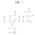
- FIG. 1 is a schematic configuration view of an optical pickup apparatus according to an exemplary embodiment of the present general inventive concept
- FIG. 2 is a schematic configuration view of an optical pickup apparatus according to another exemplary embodiment of the present general inventive concept
- FIG. 3 is a schematic configuration view of an optical pickup apparatus according to other exemplary embodiment of the present general inventive concept
- FIG. 4 is a view showing a beam focusing state of a polarization in case that a beam incident onto an objective lens with low numeral aperture (NA) is vibrated in a direction of x;
- NA numeral aperture
- FIG. 5 is a view showing a beam focusing state of a polarization in case that a beam incident onto an objective lens with high numeral aperture (NA) is vibrated in a direction of x;
- NA numeral aperture
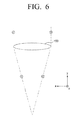
- FIG. 6 is a view showing a beam focusing state of a polarization where the beam incident onto the objective lens with low numeral aperture (NA) is vibrated in a direction of z;
- FIG. 7 is a view showing a beam focusing state of a polarization where the beam incident into the objective lens with high numeral aperture (NA) is vibrated in a direction of z;
- FIG. 8 is a comparison graph on beam spot sizes between a circular polarization and an ellipse polarization
- an optical beam forming apparatus may be applied to fields, such as an optical pickup apparatus, a three dimensional (3D) apparatus, a hologram apparatus, an image storing apparatus, a printer, etc.
- the optical pickup apparatus is mainly described below, but the field to which the optical beam forming apparatus is applied is not limited thereto. That is, the optical beam forming apparatus may be applied to all of fields to which "a principle to focus a light or laser (hereinafter, referred as 'laser') beam and to form a laser beam spot on a disc" is applied.
- FIG. 1 shows a configuration of the optical beam forming apparatus (the optical pickup apparatus).
- Like reference numerals refer to like elements throughout.
- the optical pickup apparatus includes a beam source 100, a wave plate 130, and a lens 150. Further, the optical pickup apparatus may be configured to further include a grating 102, a beam splitter 110, a feedback beam detector 190, a collimating lens 120, a reflection mirror 140, an anastigmat 170 and a beam detector 180.
- the beam source 100 may be a semiconductor beam source that emits a semiconductor laser beam.
- the beam source 100 may emit laser beams of three different wavelengths corresponding to three cases where optical discs 160 are a CD, a DVD, and a BD/CBHD, respectively. That is, the beam source 100 may emit a blue light beam having a wavelength range in the vicinity of 400nm (a wavelength less than the approximately 540nms) suitable for the BD/CBHD having a relatively higher recording density, a red light beam having a wavelength range in the vicinity of 600nm (a wavelength of approximately 600 ⁇ 660nm) suitable for the DVD having a recording density lower than that of the BD/CBHD, and an infrared light beam having a wavelength range in the vicinity of 700nm (a wavelength of approximately 700 ⁇ 800nm) suitable for the CD having a recording density lower than that of the DVD. That is to say, the semiconductor laser beam may include a plurality of laser beams having wavelengths different from each other.
- FIG. 1 there is illustrated selectively emitting laser beams of all wavelengths in case of three cases with a single beam source 100, but as illustrated in FIG. 3 , a plurality of beam sources 300 and 301 may be separately installed, or in other words, the beam sources 300 and 301 may be separate physical elements rather than the unitary physical component 100 illustrated in FIG. 1 .
- the wave plate 130 receives the laser beams emitted from the beam source and forms an ellipse polarization.
- the wave plate 130 acts to polarize the laser beam passed through the collimating lens 120.
- the wave plate 130 may include a 1/2 (half) wave plate or a 1/4 (quarter) wave plate. That is, the wave plate 130 may be disposed between the collimating lens 120 and the objective lens 150 to change a polarization component of the laser beams incident onto the objective lens 150.
- the wave plate 130 may form different polarizations according to the wavelengths of the incident laser beams. For instance, the wave plate 130 may form an ellipse polarization to a relatively longer wavelength and form a circular polarization to a relatively shorter wavelength. Further, the wave plate 130 may form the circular polarization to the relatively longer wavelength and form the ellipse polarization to the relatively shorter wavelength.
- the 1/2 wave plate is an optical part, which rotates the polarization of the laser beam passing therethrough in an angle of 90 degrees.
- the 1/2 wave plate rotates polarization components of the beams incident onto the objective lens 150 in an angle of approximately 30 degrees (or 60 degrees), so that a laser beam spot formed on the disc 160 forms the ellipse polarization, not the circular polarization.
- an ellipticity of the ellipse polarization may be configured, so that a ratio of spot diameter (full width of half maximum, or FWHM) approaches or becomes 1.
- the 1/4 wave plate as a wave plate selected so that a thickness of the plate to the incident wave comes to a 1/4 wavelength, is an optical part, which may convert a linear polarization into the circular polarization and on the contrary, the circular polarization into the linear polarization, by using a double refraction.
- the lens 150 focuses the laser beams passed through the wave plate, and forms the laser beam spot on the disc.
- the objective lens 150 may be formed of a three wave objective lens to satisfy the CD/DVD/BD. That is, to reduce the number of parts of the optical pickup apparatus and slim down the optical pickup apparatus, a three wave objective lens compatible with all wavelengths in case of three cases of the CD/DVD/BD may be used.
- the disc 160 may be various kinds of optical discs having different recording densities and different using wavelengths, such as the CD/DVD/BD.
- Data of the CD disc may be located 1.2mm from a surface thereof.
- Data of the DVD and BD discs are located 0.6mm and 0.1 mm from surfaces thereof, respectively.
- the thicker the thickness is or the larger the thickness error is the bigger an aberration may be.
- the bigger the aberration is the more the distortion of beam size occurs. If the distortion occurs, a phenomenon arises in that the beam size gets bigger.
- the beam size is relatively larger as compared to those of the DVD/BD and a data area is also large, it is insensitive to a small change in beam size.
- the beam size is smaller than that of the CD and the data area is also small, it is sensitive to a small change in beam size. Accordingly, in case of the DVD/BD, a control of the beam size is more important as compared with the CD.
- the control of the beam size by using the wave plate may be performed by small degrees or may not be performed with the BD.
- the beam detector 180 may be a Photo diode lC (PD), which receives the laser beams reflected and returned from a surface (a signal recording layer) of the disc 160 and detects an information signal and/or an error signal.
- PD Photo diode lC
- the beam splitter 110 guides the laser beams emitted from the beam source 100 toward the objective lens 150 and the laser beams reflected from the disc 160 toward the beam detector 180.
- the grating 102 divides a laser beam emitted from the beam source 100 into three beams.
- the grating 102 is a diffraction element, which divides the laser beam emitted from the beam source 100 into a 0th-order laser beam (a main laser beam) and ⁇ 1th-order laser beams (sub laser beams) to detect a tracking error signal by a three beam method, a DPP method or the like.
- the grating 102 may obtain a reproducing signal from a detecting signal of the 0th-order laser beam reflected from the optical disc 160 and obtain the tracking error signal by computing the 0th-order laser beam and the ⁇ 1th-order laser beams reflected from the optical disc 160.
- the beam splitter 110 changes a progressing path of the laser beams, toward the collimating lens 120.
- the diverged laser beams passed through the beam splitter 110 are converted into parallel laser beams by the collimating lens 120.
- the laser beams penetrated through the collimating lens 120 change their progressing path toward the objective lens 150 by means of the mirror 140.
- the anastigmat 170 generates astigmatism to detect a focus error signal with an astigmatic method.
- the collimating lens 120 may have at least one lens surface formed of an aspheric surface. Further, to correct aberrations generated by thickness differences of respective CD/DVD/BDs, thickness errors of respective discs, lasing wavelength deviations of laser diodes and wavelength changes according to the temperature, etc., the collimating lens 120 or other lens (not shown) may be moved in a direction of an optical axis.
- the feedback beam detector (or feedback photo diode) 190 may control output values of the laser beams emitted from the beam source 100.
- the reflection mirror 140 performs a role to reflect the beams passed through the wave plate 130 to direct them toward the objective lens 150 thus to change paths thereof.
- the optical pickup apparatus may use the beam source of three wavelengths and the 1/4 wave plate compatible with three wavelengths, corresponding to the three wave objective lens. Further, to change the polarization component of the beams into the ellipse polarization, not the circular polarization, the 1/4 wave plate may be disposed in an angle larger than 45 degrees and smaller than 90 degrees to the optical axis of the beams emitted from the beam source.
- FIG. 2 is a schematic optical configuration view of an optical pickup apparatus according to another exemplary embodiment of the present general inventive concept.
- the configuration in FIG. 2 is a configuration in which the wave plate 130 and the reflection mirror 140 in FIG. 1 are integrated with each other.
- the optical pickup apparatus includes a beam source 200, a wave plate and reflection mirror 240, and a lens 250. Further, the optical pickup apparatus may be configured to further include a grating 202, a beam splitter 210, a feedback beam detector 290, a collimating lens 220, an anastigmat 270 and a beam detector 280.
- FIG. 3 is a schematic optical configuration view of an optical pickup apparatus according to other exemplary embodiment of the present general inventive concept.
- the configuration in FIG. 3 is a configuration in which two beam sources (a beam source 301 in which a CD wave laser and a DVD wave laser are integrated with or to each other and a BD wave beam source 300) are separately installed and a beam splitter 311 is added to the configuration in FIG. 1 .
- the optical pickup apparatus includes a BD beam source 300, a DVD/CD beam source 301, a wave plate 330, and a lens 350. Further, the optical pickup apparatus may be configured to further include a grating 302, a beam splitter 310, a feedback beam detector 390, a collimating lens 320, a reflection mirror 340, an anastigmat 370 and a beam detector 380.
- a laser beam produced at and emitted from the beam source 100 is diffracted at the grating 102 and are divided into a 0th-order laser beam (main laser beam) and ⁇ 1 st-order laser beams (sub laser beams) to form three laser beams thus to be able to detect a tracking error.
- the laser beams passed through the grating 102 are changed into parallel beams while passing through collimating lens 120 via the beam splitter 110, and are reflected by the reflection mirror 140 toward the objective lens 150.
- the parallel laser beams are changed into circularly polarized laser beams while passing through the 1/4 wave plate 130 located in the front of the objective lens 150, and this circularly polarized laser beams form a laser beam spot on the signal recording layer of the disc 160 while passing through the objective lens 150.
- a polarized state of the laser beams incident into the collimating lens 120 via the beam splitter 110 may be changed into an ellipse form.
- the laser beam spot formed on the disc 160 may have an ellipse polarization, not a circular polarization.
- an ellipticity of the ellipse polarization may be configured, so that a ratio of spot diameter (FWHM) approaches or becomes 1.
- FIGS. 4 to 7 show polarization states of the laser beam in the vicinity of an outermost portion of the objective lens 150 according to numeral apertures of the objective lens 150.
- FIG. 4 shows a beam focusing state of a polarization when the laser beam incident into an objective lens 150 with low numeral aperture (low NA) is vibrated in a direction x
- FIG. 5 illustrates a beam focusing state of a polarization when the laser beam incident into an objective lens 150 with high numeral aperture (high low NA) is vibrated in the direction x.
- the vectors a, a' and f, f' of the laser beam, which comes to a converged or focused laser beam after passing through the objective lens 150, are changed to b, c and h, i, respectively.
- components e, g and k, m in a direction of y extend in directions opposite to each other and have the same magnitude, they offset each other when the spot is formed. Because the higher the NA is, the bigger the components in the direction of y are, the offset components in the objective lens with higher NA get larger as compared to those in the objective lens with lower NA. That is, the effect on the spot gets bigger.
- FIG. 6 shows a beam focusing state of a polarization where the laser beam incident into the objective lens 150 with low numeral aperture (low NA) is vibrated in a direction z
- FIG. 7 a beam focusing state of a polarization where the laser beam incident into the objective lens 150 with high numeral aperture (high low NA) is vibrated in the direction z.
- the polarizations where the laser beam is vibrated in the direction z are not affected before and after the laser beam passes through the objective lens 150.
- the laser beam in the vibration direction of its polarization generates the components, which weaken each other and which increase as the NA of the objective lens 150 increases.
- the laser beam in the direction perpendicular to the vibration direction does not generate the components which weaken each other. Accordingly, when a linearly polarized beam is formed in the shape of an ellipse on an objective lens 150 having a high NA, the elasticity of the ellipse, or the deviation from a circular shape, is larger.
- the objective lens 150 when the objective lens 150 focuses the linearly polarized laser beam, the laser beam of polarization direction in which the vibration direction of the polarization thereof is perpendicular to a tangent of the objective lens 150, is weakened or attenuated, whereas the laser beam of polarization direction in which the vibration direction of the polarization thereof is parallel to the tangent of the objective lens 150 is not attenuated.
- FWHM ratio of spot diameter
- FIG. 8 is a view illustrating the ratio of spot diameter (FWHM) in case that the intensity distribution of the incident laser beams is affected by a radiation angle characteristic of the semiconductor laser.
- the degree of the ellipse is caused by a difference between the directions parallel to and perpendicular to the tangent of the objective lens 150.
- the spot is almost circular in shape because a focal distance of the collimating lens 120, as 20mm, is long.
- the reason why the collimating lens 120 is selected as having the focal distance of 20mm is that in the optical memory, 20mm is near the focal distance which is pondered to have a good signal to noise (S/N) in view of a relation between an efficiency for laser beam utilization and a laser beam emitting output of the semiconductor laser.
- S/N signal to noise
- a difference between spot diameters (FWHM) in the linearly polarized laser beams (x direction, y direction) gradually gets larger, thereby increasing the degree of the ellipse or the deviation of the ellipse from a circular shape.
- a major axis or a length axis direction in the ellipse of the beam source coincides with a vibration direction of the incident linearly polarized laser beam and is a direction parallel to a laser facing surface.
- the facing surface of the beam source is perpendicular with a progressing direction or propagation direction of the laser beam.
- the laser beam passed through the objective lens forms a laser beam in the form of an ellipse with only a little asymmetry, so that the shape resembles a circle but is not a perfect circle. That is, in the ellipticity, a phenomenon occurs in that the ratio of spot diameter (FWHM) exceeds 1. What the ellipticity exceeding 1 represents is that the laser beam gets larger in size. The reason why the phenomenon as described above occurs is that an emitting laser beam of the semiconductor laser is formed of an elliptical beam. Accordingly, it can be appreciated that if the polarization of the laser beam incident onto the objective lens is configured in an elliptical polarization, the ellipticity approaches 1. According to this, it can be appreciated that in the elliptical polarization, the laser beam gets smaller in size, as compared to that of the circular polarization.
- the ratio of spot diameter is deviated by 0.05 up from 1 due to the affect of the FFP of the semiconductor laser.
- This effect of the FFP of the semiconductor laser is corrected by making the polarization of the laser beam incident onto the high NA objective lens 150 in the ellipse polarization.
- the ratio of spot diameter may be 1.05 upon entry into the objective lens, but it becomes close by 1 when laser beam is an elliptically-polarized beam.
- an optical axis of the 1/4 wave plate is inclined in angle of 45°to the laser facing surface
- a setting angle of the optical axis of the 1/4 wave plate is the same as the following [formula 2].
- the wave plate is rotated between 45° and 45 + 0.05/(0.6NA ⁇ 2-0.248NA+1.0873) x 90° or between 45 - 0.05/(0.6NA ⁇ 2-0.248NA+1.0873) x 90 ° and 45°, the affect of the FFP of the beam source 100 (the semiconductor laser) can be corrected.
- the radiation angles of the semiconductor lasers have manufacturing deviations, which may differ slightly from each other. Accordingly, the radiation angle is set as the angle represented by the above [formula 2].
- the optical pickup apparatus may be used in an apparatus for manufacturing an original disc for the disc 160, or an exposure apparatus for semiconductor.
- a semiconductor laser is not used as the beam source.
- the semiconductor laser is developed soon to be able to generate a narrow waveband of laser beam or a large output of power, it will be also used as the beam source 100.
- the laser beam spot may form the ellipse polarization, not the circular polarization, on the disc by rotating the angle of optical axis of the 1/2 wave plate installed by 30°.
- the present general inventive concept is not limited thereto, and can achieve the same object and effect by properly setting an angle of a linear polarization of the semiconductor laser diode 100 and an angle of optical axis of the 1/4 wave plate, an angle of optical axis of the 1/2 wave plate or the 1/4 wave plate, the angle of the linear polarization of the semiconductor laser diode 100 , a specification of ellipticity of the 1/4 wave plate itself, an angle difference of phase shifts, or the like.
Landscapes
- Physics & Mathematics (AREA)
- Optics & Photonics (AREA)
- Optical Head (AREA)
Applications Claiming Priority (1)
| Application Number | Priority Date | Filing Date | Title |
|---|---|---|---|
| KR1020100017020A KR20110097260A (ko) | 2010-02-25 | 2010-02-25 | 광 형성장치 |
Publications (2)
| Publication Number | Publication Date |
|---|---|
| EP2363855A2 true EP2363855A2 (de) | 2011-09-07 |
| EP2363855A3 EP2363855A3 (de) | 2011-12-07 |
Family
ID=44168302
Family Applications (1)
| Application Number | Title | Priority Date | Filing Date |
|---|---|---|---|
| EP11154631A Withdrawn EP2363855A3 (de) | 2010-02-25 | 2011-02-16 | Optische Strahlformvorrichtung |
Country Status (4)
| Country | Link |
|---|---|
| US (1) | US20110205880A1 (de) |
| EP (1) | EP2363855A3 (de) |
| KR (1) | KR20110097260A (de) |
| CN (1) | CN102194482A (de) |
Families Citing this family (2)
| Publication number | Priority date | Publication date | Assignee | Title |
|---|---|---|---|---|
| JP2013242932A (ja) * | 2010-09-08 | 2013-12-05 | Sanyo Electric Co Ltd | 光ピックアップ装置 |
| CN106513676B (zh) * | 2016-08-23 | 2019-01-22 | 西北工业大学 | 一种光斑与粉斑自动协同可控的激光金属增材制造方法 |
Family Cites Families (7)
| Publication number | Priority date | Publication date | Assignee | Title |
|---|---|---|---|---|
| US5513164A (en) * | 1992-09-11 | 1996-04-30 | Kabushiki Kaisha Toshiba | Optical recording and reproducing apparatus |
| US7050380B2 (en) * | 2000-04-18 | 2006-05-23 | Ricoh Company, Ltd. | Optical element, optical pickup unit, and optical disk drive unit |
| CN101813802A (zh) * | 2002-04-26 | 2010-08-25 | 爱普生拓优科梦株式会社 | 叠层波长板及使用它的光学拾波器 |
| JP2004046983A (ja) * | 2002-07-12 | 2004-02-12 | Mitsumi Electric Co Ltd | 光ピックアップ |
| JP4380725B2 (ja) * | 2006-04-18 | 2009-12-09 | エプソントヨコム株式会社 | 積層波長板及びこれを用いた光ピックアップ装置 |
| KR20090027947A (ko) * | 2007-09-13 | 2009-03-18 | 삼성전자주식회사 | 광 픽업장치 |
| JP2009259341A (ja) * | 2008-04-17 | 2009-11-05 | Victor Co Of Japan Ltd | 光ピックアップ装置 |
-
2010
- 2010-02-25 KR KR1020100017020A patent/KR20110097260A/ko not_active Withdrawn
-
2011
- 2011-02-16 EP EP11154631A patent/EP2363855A3/de not_active Withdrawn
- 2011-02-24 US US13/033,868 patent/US20110205880A1/en not_active Abandoned
- 2011-02-25 CN CN2011100461324A patent/CN102194482A/zh active Pending
Non-Patent Citations (1)
| Title |
|---|
| None |
Also Published As
| Publication number | Publication date |
|---|---|
| EP2363855A3 (de) | 2011-12-07 |
| US20110205880A1 (en) | 2011-08-25 |
| CN102194482A (zh) | 2011-09-21 |
| KR20110097260A (ko) | 2011-08-31 |
Similar Documents
| Publication | Publication Date | Title |
|---|---|---|
| US6947213B2 (en) | Diffractive optical element that polarizes light and an optical pickup using the same | |
| JP2002056560A (ja) | 収差補正素子及びこれを採り入れた光ピックアップ装置 | |
| EP0921521A2 (de) | Optischer Kopf mit einer mit vielen optischen Platten kompatiblen Objektivlinse | |
| US7782735B2 (en) | Optical pickup device capable of handling a plurality of laser light beams having different wavelengths | |
| US20050018585A1 (en) | Optical pickup device | |
| EP2363855A2 (de) | Optische Strahlformvorrichtung | |
| CN100395833C (zh) | 光记录介质用物镜光学系统以及使用它的光拾取装置 | |
| KR100737859B1 (ko) | 광 기록/재생장치 | |
| CN101124632A (zh) | 光拾取装置 | |
| JP2000028917A (ja) | 光情報記録媒体の記録再生用光ピックアップ装置、対物レンズ及び対物レンズの設計方法 | |
| US8064296B2 (en) | Optical head, optical disc device and information recording and/or reproducing device | |
| US7990833B2 (en) | Optical pickup device with diffraction patterns on object lens | |
| KR100651326B1 (ko) | 색수차 보정 광학계 및 그것을 이용한 광픽업장치 | |
| US20040218503A1 (en) | Objective optical element and optical pickup device | |
| CN101388231A (zh) | 光学拾取器 | |
| KR20060088827A (ko) | 광픽업 장치 | |
| US9147426B2 (en) | Optical pickup and optical information storage system including the same | |
| KR100683888B1 (ko) | 광픽업 장치 | |
| US20110188367A1 (en) | Optical pickup device | |
| US20060118704A1 (en) | Optical pickup device and optical element | |
| US8984543B2 (en) | Beam controlling method and optical pickup device for performing the method | |
| KR100477680B1 (ko) | 광픽업장치 | |
| US20060221783A1 (en) | Optical head and optical disc apparatus | |
| CN101171631A (zh) | 多辐射束光扫描装置 | |
| US20020186643A1 (en) | Optical pickup apparatus |
Legal Events
| Date | Code | Title | Description |
|---|---|---|---|
| PUAI | Public reference made under article 153(3) epc to a published international application that has entered the european phase |
Free format text: ORIGINAL CODE: 0009012 |
|
| AK | Designated contracting states |
Kind code of ref document: A2 Designated state(s): AL AT BE BG CH CY CZ DE DK EE ES FI FR GB GR HR HU IE IS IT LI LT LU LV MC MK MT NL NO PL PT RO RS SE SI SK SM TR |
|
| AX | Request for extension of the european patent |
Extension state: BA ME |
|
| PUAL | Search report despatched |
Free format text: ORIGINAL CODE: 0009013 |
|
| AK | Designated contracting states |
Kind code of ref document: A3 Designated state(s): AL AT BE BG CH CY CZ DE DK EE ES FI FR GB GR HR HU IE IS IT LI LT LU LV MC MK MT NL NO PL PT RO RS SE SI SK SM TR |
|
| AX | Request for extension of the european patent |
Extension state: BA ME |
|
| RIC1 | Information provided on ipc code assigned before grant |
Ipc: G11B 7/135 20060101ALI20111028BHEP Ipc: G11B 7/09 20060101AFI20111028BHEP |
|
| RAP1 | Party data changed (applicant data changed or rights of an application transferred) |
Owner name: SAMSUNG ELECTRONICS CO., LTD. |
|
| STAA | Information on the status of an ep patent application or granted ep patent |
Free format text: STATUS: THE APPLICATION IS DEEMED TO BE WITHDRAWN |
|
| 18D | Application deemed to be withdrawn |
Effective date: 20120609 |