EP2363876A1 - Detektor für ionisierende Strahlung - Google Patents
Detektor für ionisierende Strahlung Download PDFInfo
- Publication number
- EP2363876A1 EP2363876A1 EP11156361A EP11156361A EP2363876A1 EP 2363876 A1 EP2363876 A1 EP 2363876A1 EP 11156361 A EP11156361 A EP 11156361A EP 11156361 A EP11156361 A EP 11156361A EP 2363876 A1 EP2363876 A1 EP 2363876A1
- Authority
- EP
- European Patent Office
- Prior art keywords
- detector
- tube
- coupled
- tubes
- detector according
- Prior art date
- Legal status (The legal status is an assumption and is not a legal conclusion. Google has not performed a legal analysis and makes no representation as to the accuracy of the status listed.)
- Granted
Links
Images


Classifications
-
- H—ELECTRICITY
- H01—ELECTRIC ELEMENTS
- H01J—ELECTRIC DISCHARGE TUBES OR DISCHARGE LAMPS
- H01J47/00—Tubes for determining the presence, intensity, density or energy of radiation or particles
- H01J47/02—Ionisation chambers
-
- H—ELECTRICITY
- H01—ELECTRIC ELEMENTS
- H01J—ELECTRIC DISCHARGE TUBES OR DISCHARGE LAMPS
- H01J47/00—Tubes for determining the presence, intensity, density or energy of radiation or particles
- H01J47/12—Neutron detector tubes, e.g. BF3 tubes
- H01J47/1205—Neutron detector tubes, e.g. BF3 tubes using nuclear reactions of the type (n, alpha) in solid materials, e.g. Boron-10 (n,alpha) Lithium-7, Lithium-6 (n, alpha)Hydrogen-3
- H01J47/1211—Ionisation chambers
Definitions
- the present invention relates to the field of detectors for particles or ionizing radiation, and in particular neutron, ⁇ or X-ray detectors.
- the figure 1 schematically represents a conventional structure of a detector sensitive to ionizing radiation.
- This detector comprises a conductive tube 1 filled with a gaseous mixture, sealed at its ends by insulating plugs 3.
- a conductive wire 5 whose ends pass tightly through the plugs 3 is held taut at the center of the tube 1 by a spring 7 located inside the tube.
- a positive electrical potential applied to the wire 5 by a measuring circuit 9 makes it possible to define inside the tube an electric field which is conducive to the drift and the amplification of electrons generated during the passage of the ionizing radiation.
- the gaseous mixture contained in the tube is intended to be ionized by the particles that are to be detected, either directly or after conversion into ionizing particles.
- a mixture of CF 4 and 3 He in which the 3 He acts as a converter can be used for the detection of neutrons, and the CF 4 as the gas for stopping both particles.
- ionizing proton and triton
- the measurement circuit includes a read electronics for load signal amplitude measurement at each end of the wire. This detection mode is always complex. Another mode of operation, called “counting”, uses electronics based on the comparison, with respect to a reference voltage, of the signal measured at one end of the wire. This detection mode is generally imprecise in its current implementations.
- the uniformity of response of the detector is affected by the inaccuracy of centering of the wire inside the tube, and this centering is difficult to achieve.
- the difficulty of centering the wire 8 limits the maximum amplification gain with which the detector can operate, which has a direct impact on the performance of the detector (resolution in energy and in position).
- An ionizing radiation detector is conventionally formed of several elementary detectors whose tubes are juxtaposed. The operation of a detector depends on the quality and pressure of the gas mixture it contains. In addition, when several detectors must be used together with a minimum of space between the tubes, typically 10 mm, it is difficult to ensure the continuity of the electromagnetic shielding between the tube casing and the measuring circuit 9 without exceeding the outer diameter of the tube, which has the effect of creating dead spaces between the detectors, resulting in a loss of sensitivity of the whole.
- An object of an embodiment of the present invention is to provide a simple and inexpensive assembly to make detectors sensitive to ionizing radiation.
- An object of an embodiment of the present invention is to provide an ionizing radiation detector particularly suitable for using thin layers of converter material producing charged particles.
- Another object of an embodiment of the present invention is to provide a detector adapted to detect the presence or absence of ionizing radiation, with or without locating the point of conversion of said radiation.
- an embodiment of the present invention provides an ionizing radiation detector comprising a plurality of parallel conductor tubes containing a gaseous mixture, a conductive wire being tensioned in the center of each tube and adapted to be polarized relative to the latter, in which each tube is divided into electrically insulated longitudinal sections, all the sections of tubes of the same transverse slice being formed of a grid of electrically connected slats and each set of sections of the same slice comprising a means connecting to a detection circuit.
- the grid of blades of each slice is linked to a frame.
- each blade is coated with a layer containing a radiation converting product generating ions in response to an ionizing radiation.
- the converter product contains boron-10.
- the gas mixture is a mixture of pressurized gas containing BF 3 .
- the blades are made of aluminum.
- a first group of grid blades comprises slits which cooperate with slots of a second group of blades of the grid orthogonal to the first group.
- the detection circuit comprises a plurality of resistors coupled in series between first and second amplifiers, the nodes between the resistors being coupled to the connection means of the respective slots.
- each of the tubes comprises means for connecting the conductive wire of the tube to another detection circuit.
- the conducting wires of a group of tubes are coupled to each other.
- the other detection circuit comprises a plurality of resistors coupled in series between third and fourth amplifiers, the nodes between the resistors being coupled to the connection means of the tubes or groups of tubes. respectively.
- the detector is provided for detecting neutrons.
- An embodiment of the present invention provides a device for detecting ionizing radiation comprising a plurality of detectors as above arranged side by side.
- each of the plurality of detectors is disposed in a corresponding one of a succession of chambers forming a cylinder portion.
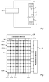
- an ionizing radiation detector comprises a parallel assembly of tubes 10-1, 10-2, 10-3, 10-n, each tube consisting of a set of stacked sections 12-1, 12-2, 12- 3 ..., 12-m insulated electrically by insulators or intervals 11.
- Each tube is traversed by a conductive element 14-1, 14-2 ... 14-n, this conductive element having for example the shape of a wire, or as will be seen below, a thin band.
- the wires are connected to a polarization and detection circuit 16, and all the tube elements corresponding to the same wafer (a gate) are connected to a polarization and detection circuit 18.
- the structure can be considered as constituted a set of cells 12-ijk, i being between 1 and n, j being between 1 and m, and k being between 1 and 1, being the number of tubes in the direction perpendicular to the plane of the figure.
- ionizing radiation interacts with one of the cells, an ionization of a gas contained in the cell occurs and this ionization provides an electrical signal on the one hand on the central conductor, on the other hand on the wall of the tube. There is thus an indication in x, y and z of the location at which the ionization has occurred.
- FIG. 3 very schematically represents an assembly of detectors.
- This detector assembly comprises vertically stacked slices in the y direction, the x axis designates the horizontal direction and the z axis designates the direction in which the ionizing radiation is likely to arrive.
- circuits 16 and 18 it will be possible to precisely determine the cell at which a conversion of a radiation, for example of a neutron, has taken place.
- the entire structure is disposed in an enclosure filled with a clean gas to be ionized.
- the gas is for example under pressure.
- the converter product reacting to the ionizing radiation may be, as in the prior art described above, a gas such as helium-3 or BF 3 .
- a gas such as helium-3 or BF 3 .
- It may also be a reactive material deposited in a thin layer, alone or in combination with another material, on the walls of each tube, or else the combination of helium-3 or BF 3 and layers thin reactive material.
- This reactive material may be boron-10, capable of interacting with a neutron to provide lithium-7 and an alpha-4 particle.
- Other products that may be used are known in the art.
- helium 3 is extremely expensive and hardly available.
- the use of BF 3 gas and a boron coating on the walls of each tube leads to a double effect for the detection of neutrons.
- the figure 4 is an exploded view of an exemplary embodiment of a horizontal slice (disposed between two adjacent horizontal planes), which comprises a section of each tube of a detector according to an embodiment of the present invention.
- the wafer is formed from a frame 21 whose opposite edges are provided with grooves 22 for receiving first plates 23 oriented in the z direction.
- the plates 23 are provided with slots 24 in which are intended to fit orthogonal plates 25 provided with slots 26 cooperating with the slots 24.
- the ends of the plates 25 are received in opposite slots 27 of the edges of the frame oriented according to the direction z.
- the contact between the plates 23, 25 and the frame 21 and between the plates is conductive. This gives the set of cells or sections of a horizontal slice (a grid) of the detector.
- FIG. 4 an insulating joint 28 for separating two slices of a detector according to embodiments of the invention.
- each section and each wire passing through a set of vertically aligned sections are connected to a polarization and detection system so that the wires constitute anodes and the walls of the cathode wafer sections to attract the ionized gases produced by the conversion of ionizing bombardment.
- each wire and cell slice is connected by a separate conductor to recognize the cell at which the ionizing radiation has been converted. In fact, this discrimination of the cells is not always necessary. In some cases, one simply wants, for example in airport security devices, to know if a piece of luggage or a container contains radioactive products emitting neutrons. It will be enough then to connect together all the wires and all the sections to have a very simple device to use, with few lines of exit.
- each section may have a side of the order of 2 cm and a height of the order of 2 cm and the entire structure may have a height of about 3 m.
- Those skilled in the art will be able to adapt these dimensions to their needs.
- an advantage of using a grid structure is that the section of each tube can have small dimensions. For example, rather than being 2 cm as described above, the lateral length of each section of each rectangular tube is for example only 4 to 10 mm. This allows the electrons resulting from a reaction to have a short flight time and thus a relatively high gas pressure can be used in the tube, for example greater than 2.10 5 Pa. This is particularly advantageous when the gas is from BF 3 .
- a grid structure can advantageously be consisting of plates or blades 23, 25 of aluminum having for example a thickness of 0.5 mm or less.
- the figure 5 shows in more detail a radiation detector and in particular an example of a detection circuit of the polarization and detection device 18.
- the detection circuit comprises a resistor network 30 comprising a succession of resistors 30-1 to 30-7 in series. .
- Each resistor has for example a value between 100 and 200 ohms.
- Both ends of the resistor network are coupled to amplifiers 32 and 34, respectively, which provide respective output voltages VA and V B. Based on these voltages, the slice in which radiation is detected can be identified. In particular, the position is indicated by calculating V A / (V A + V B ).
- An advantage of the use of the resistance network 30 of the figure 5 is that it reduces the number of output lines to two rather than to a number equal to the number of slices.
- the figure 6 is a top view of the upper edge of the radiation detector, and shows the polarization and detection circuit 16 according to an example in which groups of conductive wires 14 of each tube are coupled to each other.
- the tube block son, 4 in depth and 2 in width are coupled to each other, although other shapes and dimensions of blocks can be chosen. This further reduces the number of output lines for the radiation detector.
- one or more resistive networks may be used to reduce the number of connections to the wires.
- the figure 6 illustrates the example of a resistor network 36 having three series resistors 36-1 to 36-3 and amplifiers 38 and 40 at each end. providing voltages V C and V D.
- the corresponding nodes of the resistor network 36 are coupled to four of the interconnected wire groups.
- the bias circuit for applying a bias voltage to these wires is also shown and includes, for example, a high voltage supply HV coupled by a resistor at the end of the resistor network, on the amplifier side 40.
- a capacitor 41 is coupled between the resistor network and the amplifier 40, while the input of the amplifier 40 is also coupled by a resistance to ground.
- the figure 6 is an example of a resistor network 42 having three resistors connected in series 42-1 to 42-3 and amplifiers 44 and 46 at each end providing voltages V E and V F. Corresponding nodes of the resistor network 42 are coupled to four of the interconnected wire groups.
- the bias circuit for applying a bias voltage to these wires is also shown and includes, for example, a high voltage power supply coupled by a resistor at the end of the resistor network, on the amplifier side 46.
- a capacitor 47 is coupled between the resistor network and the amplifier 46 while the input of the amplifier 47 is also coupled by a resistance to ground.
- the figure 7 is a top view illustrating a radiation detection device 50 having a curved wall 51 consisting of a succession of chambers 52 each of which contains the pressurized gas detectors.
- the wall 51 is for example made of metal sheets having a thickness of the order of 3 mm.
- Each chamber 52 comprises a radiation detector as described above, an example 56 of which is shown.
- the slices of the same level of neighboring detectors are coupled to each other, for example in pairs, to provide combined outputs, a level of these outputs being designated by references 58-1 to 58-6 in figure 7 . This further reduces the number of output lines.
- Such a device can be used in a scientific application to detect the direction of radiation from a source 54 in the center of a partial cylinder consisting of the curved wall 51.
Landscapes
- Physics & Mathematics (AREA)
- Chemical & Material Sciences (AREA)
- Engineering & Computer Science (AREA)
- Chemical Kinetics & Catalysis (AREA)
- High Energy & Nuclear Physics (AREA)
- Materials Engineering (AREA)
- Measurement Of Radiation (AREA)
Priority Applications (1)
| Application Number | Priority Date | Filing Date | Title |
|---|---|---|---|
| US13/038,915 US8481957B2 (en) | 2010-03-02 | 2011-03-02 | Ionizing radiation detector |
Applications Claiming Priority (1)
| Application Number | Priority Date | Filing Date | Title |
|---|---|---|---|
| FR1051502A FR2957188B1 (fr) | 2010-03-02 | 2010-03-02 | Detecteur de rayonnement ionisant |
Publications (2)
| Publication Number | Publication Date |
|---|---|
| EP2363876A1 true EP2363876A1 (de) | 2011-09-07 |
| EP2363876B1 EP2363876B1 (de) | 2015-04-29 |
Family
ID=42979826
Family Applications (1)
| Application Number | Title | Priority Date | Filing Date |
|---|---|---|---|
| EP20110156361 Active EP2363876B1 (de) | 2010-03-02 | 2011-03-01 | Detektor für ionisierende Strahlung |
Country Status (4)
| Country | Link |
|---|---|
| US (1) | US8481957B2 (de) |
| EP (1) | EP2363876B1 (de) |
| JP (1) | JP2011191295A (de) |
| FR (1) | FR2957188B1 (de) |
Families Citing this family (2)
| Publication number | Priority date | Publication date | Assignee | Title |
|---|---|---|---|---|
| DE102012108766A1 (de) * | 2012-09-18 | 2014-03-20 | CDT Cascade Detector Technologies GmbH | Neutronendetektoreinheit sowie Neutronendetektoranordnung |
| US9847215B2 (en) * | 2014-11-08 | 2017-12-19 | Jefferson Science Associates, Llc | Method for detecting and distinguishing between specific types of environmental radiation using a high pressure ionization chamber with pulse-mode readout |
Citations (6)
| Publication number | Priority date | Publication date | Assignee | Title |
|---|---|---|---|---|
| FR943262A (fr) * | 1946-03-14 | 1949-03-03 | Texaco Development Corp | Perfectionnements aux détecteurs de radiation |
| US4447727A (en) * | 1981-06-30 | 1984-05-08 | Irt Corporation | Large area neutron proportional counter and portal monitor detector |
| US5071381A (en) * | 1990-03-07 | 1991-12-10 | Advanced Interconnect Technology Inc. | Process for the manufacture of straw tube drift chambers |
| DE19907042A1 (de) * | 1999-02-19 | 2000-08-31 | Gsf Forschungszentrum Umwelt | Modularer Ionisationsdetektor |
| US20050258373A1 (en) * | 2002-11-13 | 2005-11-24 | Lacy Jeffrey L | Boron coated straw neutron detector |
| US20100012851A1 (en) * | 2008-07-18 | 2010-01-21 | Brookhaven Science Associates, Llc | Multi-Anode Ionization Chamber |
Family Cites Families (4)
| Publication number | Priority date | Publication date | Assignee | Title |
|---|---|---|---|---|
| US5734689A (en) * | 1996-01-29 | 1998-03-31 | The United States Of America As Represented By The Secretary Of The Navy | Thermal neutron detector |
| US7233007B2 (en) * | 2004-03-01 | 2007-06-19 | Nova Scientific, Inc. | Radiation detectors and methods of detecting radiation |
| WO2007138604A2 (en) * | 2006-06-01 | 2007-12-06 | Ben-Gurion University Of The Negev Research And Development Authority | Denitrification treatment system and method |
| US7633062B2 (en) * | 2006-10-27 | 2009-12-15 | Los Alamos National Security, Llc | Radiation portal monitor system and method |
-
2010
- 2010-03-02 FR FR1051502A patent/FR2957188B1/fr not_active Expired - Fee Related
-
2011
- 2011-03-01 EP EP20110156361 patent/EP2363876B1/de active Active
- 2011-03-02 JP JP2011044954A patent/JP2011191295A/ja active Pending
- 2011-03-02 US US13/038,915 patent/US8481957B2/en active Active
Patent Citations (6)
| Publication number | Priority date | Publication date | Assignee | Title |
|---|---|---|---|---|
| FR943262A (fr) * | 1946-03-14 | 1949-03-03 | Texaco Development Corp | Perfectionnements aux détecteurs de radiation |
| US4447727A (en) * | 1981-06-30 | 1984-05-08 | Irt Corporation | Large area neutron proportional counter and portal monitor detector |
| US5071381A (en) * | 1990-03-07 | 1991-12-10 | Advanced Interconnect Technology Inc. | Process for the manufacture of straw tube drift chambers |
| DE19907042A1 (de) * | 1999-02-19 | 2000-08-31 | Gsf Forschungszentrum Umwelt | Modularer Ionisationsdetektor |
| US20050258373A1 (en) * | 2002-11-13 | 2005-11-24 | Lacy Jeffrey L | Boron coated straw neutron detector |
| US20100012851A1 (en) * | 2008-07-18 | 2010-01-21 | Brookhaven Science Associates, Llc | Multi-Anode Ionization Chamber |
Non-Patent Citations (1)
| Title |
|---|
| KLIAUGA P ET AL: "A MULTI-ELEMENT PROPORTIONAL COUNTER FOR RADIATION PROTECTION MEASUREMENTS", HEALTH PHYSICS, LIPPINCOTT, WILLIAMS & WILKINS, HAGERSTON, MD, USA, vol. 57, no. 4, 1 October 1989 (1989-10-01), pages 631 - 636, XP000070331, ISSN: 0017-9078 * |
Also Published As
| Publication number | Publication date |
|---|---|
| US20110215251A1 (en) | 2011-09-08 |
| JP2011191295A (ja) | 2011-09-29 |
| US8481957B2 (en) | 2013-07-09 |
| FR2957188B1 (fr) | 2012-08-17 |
| FR2957188A1 (fr) | 2011-09-09 |
| EP2363876B1 (de) | 2015-04-29 |
Similar Documents
| Publication | Publication Date | Title |
|---|---|---|
| EP0855086B1 (de) | Lage empfindlicher hochanflösungs detektor für hohe flüsse ionisierender teilchen | |
| EP0678896B1 (de) | Medizinischer Bilderzeugungsvorrichtung mittels ionisierender Röntgen- oder Gamma Strahlungen niedriger Dosis | |
| EP0810631B1 (de) | Hochauflösende radiografische Bilderzeugungsvorrichtung | |
| EP0742954A1 (de) | Detektor für ionisierende strahlung mit mikroproportionalzätzlröhre | |
| EP0515261B1 (de) | In Keramik gefertigte Elektronenvervielfacherstruktur vorzugsweise für Elektronenvervielfacher und Herstellungsverfahren derselben | |
| EP2363876B1 (de) | Detektor für ionisierende Strahlung | |
| FR2680010A1 (fr) | Detecteur a gaz de rayonnement ionisant. | |
| EP0064913B1 (de) | Mehrelementenröntgendetektor | |
| FR2514557A1 (fr) | Spectrometre magnetique miniature a structure coaxiale | |
| EP0010474B1 (de) | Strahlungsdetektor | |
| FR2951580A1 (fr) | Dispositif d'imagerie radiographique et detecteur pour un dispositif d'imagerie radiographique | |
| EP2483908A1 (de) | Vorrichtung und verfahren zur liniensteuerung eines energiestrahls | |
| EP0593333A1 (de) | Detektorzelle, Detektor, Sensor für Spektroskop | |
| WO2008129159A1 (fr) | Dispositif de multiplication des electrons et systeme de detection de rayonnements ionisants | |
| FR2504278A1 (fr) | Detecteur de rayons x | |
| EP1410420A1 (de) | Detektor für ionisierende strahlung mit einer festen strahlungswandlungsplatte und verfahren zu seiner herstellung | |
| EP1343194A1 (de) | Strahlungsdetektoren und autoradiographische Abbildungsvorrichtungen mit solcher Detektoren | |
| Stelzer | Some recent developments in nuclear charged particle detectors | |
| WO1990004851A1 (fr) | Procede et dispositif de localisation bidimensionnelle de particules neutres, notamment pour faibles taux de comptage | |
| EP1131843A1 (de) | Gasgefüllter photonendetektor | |
| WO1997004335A1 (fr) | Detecteur de particules sensible a la position et transparent | |
| Shinde et al. | Fabrication and Characterization of Glass Resistive Plate Chamber (RPC) | |
| WO1993022792A1 (fr) | Dispositif pour la detection et la localisation bidimensionnelle de neutrons | |
| FR3076948A1 (fr) | Detecteur de photons x dans la gamme d'energie 1 a 5 kev | |
| EP1416296A2 (de) | Elektronische Einrichtung zum Messen der Strahlendosis |
Legal Events
| Date | Code | Title | Description |
|---|---|---|---|
| PUAI | Public reference made under article 153(3) epc to a published international application that has entered the european phase |
Free format text: ORIGINAL CODE: 0009012 |
|
| AK | Designated contracting states |
Kind code of ref document: A1 Designated state(s): AL AT BE BG CH CY CZ DE DK EE ES FI FR GB GR HR HU IE IS IT LI LT LU LV MC MK MT NL NO PL PT RO RS SE SI SK SM TR |
|
| AX | Request for extension of the european patent |
Extension state: BA ME |
|
| 17P | Request for examination filed |
Effective date: 20111221 |
|
| GRAP | Despatch of communication of intention to grant a patent |
Free format text: ORIGINAL CODE: EPIDOSNIGR1 |
|
| INTG | Intention to grant announced |
Effective date: 20141117 |
|
| GRAS | Grant fee paid |
Free format text: ORIGINAL CODE: EPIDOSNIGR3 |
|
| GRAA | (expected) grant |
Free format text: ORIGINAL CODE: 0009210 |
|
| AK | Designated contracting states |
Kind code of ref document: B1 Designated state(s): AL AT BE BG CH CY CZ DE DK EE ES FI FR GB GR HR HU IE IS IT LI LT LU LV MC MK MT NL NO PL PT RO RS SE SI SK SM TR |
|
| REG | Reference to a national code |
Ref country code: GB Ref legal event code: FG4D Free format text: NOT ENGLISH |
|
| REG | Reference to a national code |
Ref country code: CH Ref legal event code: EP |
|
| REG | Reference to a national code |
Ref country code: AT Ref legal event code: REF Ref document number: 724849 Country of ref document: AT Kind code of ref document: T Effective date: 20150515 |
|
| REG | Reference to a national code |
Ref country code: IE Ref legal event code: FG4D Free format text: LANGUAGE OF EP DOCUMENT: FRENCH |
|
| REG | Reference to a national code |
Ref country code: DE Ref legal event code: R096 Ref document number: 602011016035 Country of ref document: DE Effective date: 20150611 |
|
| REG | Reference to a national code |
Ref country code: SE Ref legal event code: TRGR |
|
| REG | Reference to a national code |
Ref country code: NL Ref legal event code: VDEP Effective date: 20150429 |
|
| REG | Reference to a national code |
Ref country code: AT Ref legal event code: MK05 Ref document number: 724849 Country of ref document: AT Kind code of ref document: T Effective date: 20150429 |
|
| REG | Reference to a national code |
Ref country code: LT Ref legal event code: MG4D |
|
| PG25 | Lapsed in a contracting state [announced via postgrant information from national office to epo] |
Ref country code: NL Free format text: LAPSE BECAUSE OF FAILURE TO SUBMIT A TRANSLATION OF THE DESCRIPTION OR TO PAY THE FEE WITHIN THE PRESCRIBED TIME-LIMIT Effective date: 20150429 |
|
| PG25 | Lapsed in a contracting state [announced via postgrant information from national office to epo] |
Ref country code: FI Free format text: LAPSE BECAUSE OF FAILURE TO SUBMIT A TRANSLATION OF THE DESCRIPTION OR TO PAY THE FEE WITHIN THE PRESCRIBED TIME-LIMIT Effective date: 20150429 Ref country code: NO Free format text: LAPSE BECAUSE OF FAILURE TO SUBMIT A TRANSLATION OF THE DESCRIPTION OR TO PAY THE FEE WITHIN THE PRESCRIBED TIME-LIMIT Effective date: 20150729 Ref country code: PT Free format text: LAPSE BECAUSE OF FAILURE TO SUBMIT A TRANSLATION OF THE DESCRIPTION OR TO PAY THE FEE WITHIN THE PRESCRIBED TIME-LIMIT Effective date: 20150831 Ref country code: ES Free format text: LAPSE BECAUSE OF FAILURE TO SUBMIT A TRANSLATION OF THE DESCRIPTION OR TO PAY THE FEE WITHIN THE PRESCRIBED TIME-LIMIT Effective date: 20150429 Ref country code: LT Free format text: LAPSE BECAUSE OF FAILURE TO SUBMIT A TRANSLATION OF THE DESCRIPTION OR TO PAY THE FEE WITHIN THE PRESCRIBED TIME-LIMIT Effective date: 20150429 Ref country code: HR Free format text: LAPSE BECAUSE OF FAILURE TO SUBMIT A TRANSLATION OF THE DESCRIPTION OR TO PAY THE FEE WITHIN THE PRESCRIBED TIME-LIMIT Effective date: 20150429 |
|
| PG25 | Lapsed in a contracting state [announced via postgrant information from national office to epo] |
Ref country code: LV Free format text: LAPSE BECAUSE OF FAILURE TO SUBMIT A TRANSLATION OF THE DESCRIPTION OR TO PAY THE FEE WITHIN THE PRESCRIBED TIME-LIMIT Effective date: 20150429 Ref country code: AT Free format text: LAPSE BECAUSE OF FAILURE TO SUBMIT A TRANSLATION OF THE DESCRIPTION OR TO PAY THE FEE WITHIN THE PRESCRIBED TIME-LIMIT Effective date: 20150429 Ref country code: IS Free format text: LAPSE BECAUSE OF FAILURE TO SUBMIT A TRANSLATION OF THE DESCRIPTION OR TO PAY THE FEE WITHIN THE PRESCRIBED TIME-LIMIT Effective date: 20150829 Ref country code: RS Free format text: LAPSE BECAUSE OF FAILURE TO SUBMIT A TRANSLATION OF THE DESCRIPTION OR TO PAY THE FEE WITHIN THE PRESCRIBED TIME-LIMIT Effective date: 20150429 Ref country code: GR Free format text: LAPSE BECAUSE OF FAILURE TO SUBMIT A TRANSLATION OF THE DESCRIPTION OR TO PAY THE FEE WITHIN THE PRESCRIBED TIME-LIMIT Effective date: 20150730 |
|
| PG25 | Lapsed in a contracting state [announced via postgrant information from national office to epo] |
Ref country code: DK Free format text: LAPSE BECAUSE OF FAILURE TO SUBMIT A TRANSLATION OF THE DESCRIPTION OR TO PAY THE FEE WITHIN THE PRESCRIBED TIME-LIMIT Effective date: 20150429 Ref country code: EE Free format text: LAPSE BECAUSE OF FAILURE TO SUBMIT A TRANSLATION OF THE DESCRIPTION OR TO PAY THE FEE WITHIN THE PRESCRIBED TIME-LIMIT Effective date: 20150429 |
|
| REG | Reference to a national code |
Ref country code: DE Ref legal event code: R097 Ref document number: 602011016035 Country of ref document: DE |
|
| PG25 | Lapsed in a contracting state [announced via postgrant information from national office to epo] |
Ref country code: CZ Free format text: LAPSE BECAUSE OF FAILURE TO SUBMIT A TRANSLATION OF THE DESCRIPTION OR TO PAY THE FEE WITHIN THE PRESCRIBED TIME-LIMIT Effective date: 20150429 Ref country code: SK Free format text: LAPSE BECAUSE OF FAILURE TO SUBMIT A TRANSLATION OF THE DESCRIPTION OR TO PAY THE FEE WITHIN THE PRESCRIBED TIME-LIMIT Effective date: 20150429 Ref country code: PL Free format text: LAPSE BECAUSE OF FAILURE TO SUBMIT A TRANSLATION OF THE DESCRIPTION OR TO PAY THE FEE WITHIN THE PRESCRIBED TIME-LIMIT Effective date: 20150429 Ref country code: RO Free format text: LAPSE BECAUSE OF NON-PAYMENT OF DUE FEES Effective date: 20150429 |
|
| PLBE | No opposition filed within time limit |
Free format text: ORIGINAL CODE: 0009261 |
|
| STAA | Information on the status of an ep patent application or granted ep patent |
Free format text: STATUS: NO OPPOSITION FILED WITHIN TIME LIMIT |
|
| REG | Reference to a national code |
Ref country code: FR Ref legal event code: PLFP Year of fee payment: 6 |
|
| 26N | No opposition filed |
Effective date: 20160201 |
|
| PG25 | Lapsed in a contracting state [announced via postgrant information from national office to epo] |
Ref country code: IT Free format text: LAPSE BECAUSE OF FAILURE TO SUBMIT A TRANSLATION OF THE DESCRIPTION OR TO PAY THE FEE WITHIN THE PRESCRIBED TIME-LIMIT Effective date: 20150429 |
|
| PG25 | Lapsed in a contracting state [announced via postgrant information from national office to epo] |
Ref country code: SI Free format text: LAPSE BECAUSE OF FAILURE TO SUBMIT A TRANSLATION OF THE DESCRIPTION OR TO PAY THE FEE WITHIN THE PRESCRIBED TIME-LIMIT Effective date: 20150429 |
|
| PG25 | Lapsed in a contracting state [announced via postgrant information from national office to epo] |
Ref country code: BE Free format text: LAPSE BECAUSE OF NON-PAYMENT OF DUE FEES Effective date: 20160331 |
|
| PG25 | Lapsed in a contracting state [announced via postgrant information from national office to epo] |
Ref country code: LU Free format text: LAPSE BECAUSE OF FAILURE TO SUBMIT A TRANSLATION OF THE DESCRIPTION OR TO PAY THE FEE WITHIN THE PRESCRIBED TIME-LIMIT Effective date: 20160301 Ref country code: MC Free format text: LAPSE BECAUSE OF FAILURE TO SUBMIT A TRANSLATION OF THE DESCRIPTION OR TO PAY THE FEE WITHIN THE PRESCRIBED TIME-LIMIT Effective date: 20150429 |
|
| REG | Reference to a national code |
Ref country code: CH Ref legal event code: PL |
|
| REG | Reference to a national code |
Ref country code: IE Ref legal event code: MM4A |
|
| PG25 | Lapsed in a contracting state [announced via postgrant information from national office to epo] |
Ref country code: IE Free format text: LAPSE BECAUSE OF NON-PAYMENT OF DUE FEES Effective date: 20160301 Ref country code: CH Free format text: LAPSE BECAUSE OF NON-PAYMENT OF DUE FEES Effective date: 20160331 Ref country code: LI Free format text: LAPSE BECAUSE OF NON-PAYMENT OF DUE FEES Effective date: 20160331 |
|
| REG | Reference to a national code |
Ref country code: FR Ref legal event code: PLFP Year of fee payment: 7 |
|
| PG25 | Lapsed in a contracting state [announced via postgrant information from national office to epo] |
Ref country code: MT Free format text: LAPSE BECAUSE OF FAILURE TO SUBMIT A TRANSLATION OF THE DESCRIPTION OR TO PAY THE FEE WITHIN THE PRESCRIBED TIME-LIMIT Effective date: 20150429 |
|
| REG | Reference to a national code |
Ref country code: FR Ref legal event code: PLFP Year of fee payment: 8 |
|
| PG25 | Lapsed in a contracting state [announced via postgrant information from national office to epo] |
Ref country code: SM Free format text: LAPSE BECAUSE OF FAILURE TO SUBMIT A TRANSLATION OF THE DESCRIPTION OR TO PAY THE FEE WITHIN THE PRESCRIBED TIME-LIMIT Effective date: 20150429 Ref country code: HU Free format text: LAPSE BECAUSE OF FAILURE TO SUBMIT A TRANSLATION OF THE DESCRIPTION OR TO PAY THE FEE WITHIN THE PRESCRIBED TIME-LIMIT; INVALID AB INITIO Effective date: 20110301 Ref country code: CY Free format text: LAPSE BECAUSE OF FAILURE TO SUBMIT A TRANSLATION OF THE DESCRIPTION OR TO PAY THE FEE WITHIN THE PRESCRIBED TIME-LIMIT Effective date: 20150429 |
|
| PG25 | Lapsed in a contracting state [announced via postgrant information from national office to epo] |
Ref country code: MK Free format text: LAPSE BECAUSE OF FAILURE TO SUBMIT A TRANSLATION OF THE DESCRIPTION OR TO PAY THE FEE WITHIN THE PRESCRIBED TIME-LIMIT Effective date: 20150429 Ref country code: TR Free format text: LAPSE BECAUSE OF FAILURE TO SUBMIT A TRANSLATION OF THE DESCRIPTION OR TO PAY THE FEE WITHIN THE PRESCRIBED TIME-LIMIT Effective date: 20150429 |
|
| PG25 | Lapsed in a contracting state [announced via postgrant information from national office to epo] |
Ref country code: BG Free format text: LAPSE BECAUSE OF FAILURE TO SUBMIT A TRANSLATION OF THE DESCRIPTION OR TO PAY THE FEE WITHIN THE PRESCRIBED TIME-LIMIT Effective date: 20150429 |
|
| PG25 | Lapsed in a contracting state [announced via postgrant information from national office to epo] |
Ref country code: AL Free format text: LAPSE BECAUSE OF FAILURE TO SUBMIT A TRANSLATION OF THE DESCRIPTION OR TO PAY THE FEE WITHIN THE PRESCRIBED TIME-LIMIT Effective date: 20150429 |
|
| P01 | Opt-out of the competence of the unified patent court (upc) registered |
Effective date: 20230411 |
|
| PGFP | Annual fee paid to national office [announced via postgrant information from national office to epo] |
Ref country code: SE Payment date: 20260320 Year of fee payment: 16 |
|
| PGFP | Annual fee paid to national office [announced via postgrant information from national office to epo] |
Ref country code: GB Payment date: 20260323 Year of fee payment: 16 |
|
| PGFP | Annual fee paid to national office [announced via postgrant information from national office to epo] |
Ref country code: DE Payment date: 20260313 Year of fee payment: 16 |
|
| PGFP | Annual fee paid to national office [announced via postgrant information from national office to epo] |
Ref country code: FR Payment date: 20260330 Year of fee payment: 16 |