EP2363930A1 - Schaltanordnung für eine elektrische Schaltanlage - Google Patents
Schaltanordnung für eine elektrische Schaltanlage Download PDFInfo
- Publication number
- EP2363930A1 EP2363930A1 EP10002053A EP10002053A EP2363930A1 EP 2363930 A1 EP2363930 A1 EP 2363930A1 EP 10002053 A EP10002053 A EP 10002053A EP 10002053 A EP10002053 A EP 10002053A EP 2363930 A1 EP2363930 A1 EP 2363930A1
- Authority
- EP
- European Patent Office
- Prior art keywords
- electrical contact
- breaker
- electrical
- switch arrangement
- switchgear
- Prior art date
- Legal status (The legal status is an assumption and is not a legal conclusion. Google has not performed a legal analysis and makes no representation as to the accuracy of the status listed.)
- Withdrawn
Links
- 230000001419 dependent effect Effects 0.000 claims 1
- 238000009434 installation Methods 0.000 description 6
- 229910052751 metal Inorganic materials 0.000 description 6
- 239000002184 metal Substances 0.000 description 6
- 239000004020 conductor Substances 0.000 description 4
- 238000005192 partition Methods 0.000 description 4
- 238000010586 diagram Methods 0.000 description 3
- 239000012071 phase Substances 0.000 description 3
- RYGMFSIKBFXOCR-UHFFFAOYSA-N Copper Chemical compound [Cu] RYGMFSIKBFXOCR-UHFFFAOYSA-N 0.000 description 2
- 229910052802 copper Inorganic materials 0.000 description 2
- 239000010949 copper Substances 0.000 description 2
- 238000009413 insulation Methods 0.000 description 2
- 238000012423 maintenance Methods 0.000 description 2
- 239000008385 outer phase Substances 0.000 description 2
- 238000012360 testing method Methods 0.000 description 2
- 239000004411 aluminium Substances 0.000 description 1
- 229910052782 aluminium Inorganic materials 0.000 description 1
- XAGFODPZIPBFFR-UHFFFAOYSA-N aluminium Chemical compound [Al] XAGFODPZIPBFFR-UHFFFAOYSA-N 0.000 description 1
- 230000004888 barrier function Effects 0.000 description 1
- 238000010616 electrical installation Methods 0.000 description 1
- 239000003822 epoxy resin Substances 0.000 description 1
- 229910001385 heavy metal Inorganic materials 0.000 description 1
- 238000007689 inspection Methods 0.000 description 1
- 239000000463 material Substances 0.000 description 1
- 238000012986 modification Methods 0.000 description 1
- 230000004048 modification Effects 0.000 description 1
- 229920000647 polyepoxide Polymers 0.000 description 1
Images




Classifications
-
- H—ELECTRICITY
- H02—GENERATION; CONVERSION OR DISTRIBUTION OF ELECTRIC POWER
- H02B—BOARDS, SUBSTATIONS OR SWITCHING ARRANGEMENTS FOR THE SUPPLY OR DISTRIBUTION OF ELECTRIC POWER
- H02B11/00—Switchgear having carriage withdrawable for isolation
- H02B11/02—Details
- H02B11/04—Isolating-contacts, e.g. mountings or shieldings
-
- H—ELECTRICITY
- H02—GENERATION; CONVERSION OR DISTRIBUTION OF ELECTRIC POWER
- H02B—BOARDS, SUBSTATIONS OR SWITCHING ARRANGEMENTS FOR THE SUPPLY OR DISTRIBUTION OF ELECTRIC POWER
- H02B1/00—Frameworks, boards, panels, desks, casings; Details of substations or switching arrangements
- H02B1/26—Casings; Parts thereof or accessories therefor
- H02B1/28—Casings; Parts thereof or accessories therefor dustproof, splashproof, drip-proof, waterproof or flameproof
-
- H—ELECTRICITY
- H01—ELECTRIC ELEMENTS
- H01H—ELECTRIC SWITCHES; RELAYS; SELECTORS; EMERGENCY PROTECTIVE DEVICES
- H01H1/00—Contacts
- H01H1/12—Contacts characterised by the manner in which co-operating contacts engage
- H01H1/36—Contacts characterised by the manner in which co-operating contacts engage by sliding
- H01H1/365—Bridging contacts
-
- H—ELECTRICITY
- H01—ELECTRIC ELEMENTS
- H01H—ELECTRIC SWITCHES; RELAYS; SELECTORS; EMERGENCY PROTECTIVE DEVICES
- H01H33/00—High-tension or heavy-current switches with arc-extinguishing or arc-preventing means
- H01H33/60—Switches wherein the means for extinguishing or preventing the arc do not include separate means for obtaining or increasing flow of arc-extinguishing fluid
- H01H33/66—Vacuum switches
- H01H33/662—Housings or protective screens
Definitions
- the present invention relates to a switch arrangement for electrical switchgear.
- a switchgear is an integrated assembly of switches, buses fuses and other components used to isolate electrical equipment at an electrical installation, for example, an electrical power sub-station. Switchgear is used to both deenergise equipment to allow work to be done and to clear faults downstream of the switchgear. Switchgear is often housed in a metal cabinet at the installation.
- 'fixed switchgear' In known installations, a distinction is made between so called 'fixed switchgear' and so called 'withdrawable switchgear'.
- fixed switchgear the main circuit breaker is fastened within the installation by fasteners, for example bolts, and cannot be removed from the installation without using tools to undo the fasteners.
- withdrawable switchgear additional constructional features enable the main circuit breaker to be withdrawn from the installation (and put back in) with a minimum usage of tools or with no usage of tools. Accordingly, in a withdrawable switchgear, the main circuit breaker can be removed quickly for maintenance or replacement or to provide easy access to other components in the installation.
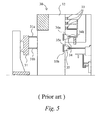
- FIG. 5 is a schematic illustration of a conventional withdrawable switchgear 30 comprising, a circuit breaker 31 comprising a first breaker contact 31a and second breaker contact 31b, and a cabinet 32 containing busbars 33.
- the switchgear 30 further comprises a first terminal 34 and a second terminal 35 each comprising a respective electrically insulating housing 34a and 35a.
- the insulating housing 34a contains an electrical contact 34b connected to a busbar 33 and the insulating housing 35a contains an electrical contact 35b connected to a cable connection 36 which is for connecting to a cable (not shown) routed to a load (not shown).
- the circuit breaker is shown in the withdrawn position in which there is no electrical connection between the busbar 33 and the load (not shown).
- the breaker 31 In a service position, the breaker 31 is located in the cabinet 32 with the first breaker contact 31a inserted into the first housing 34a engaging the contact 34b and the second breaker contact 31b is inserted into the second housing 35 engaging the contact 35b. In this way, when the breaker is closed (e.g. not tripped) an electrical connection exists between the busbar 33 and the load (not shown) through the breaker 31. This configuration is not compact.
- a switch arrangement for an electrical switchgear comprising: a terminal arrangement comprising an insulating housing containing a first electrical contact and a second electrical contact which are spaced apart along an axial direction; and a breaker moveable along the axial direction in the housing to a first position, wherein, when the breaker is in the first position and closed it electrically connects the first electrical contact and the second electrical contact.
- This provides a particularly compact arrangement.
- the breaker may be moveable to a second position in which it is withdrawn from the switchgear.
- the first electrical contact is for a bus and the second electrical contact is for a load connection.
- the housing may be unitary or it may be split into a plurality of separate sections along the axial direction, with one of the electrical contacts in one of the sections and the other of the electrical contacts in another of the sections.
- a switch arrangement 1 for an electrical switchgear 2 comprises an electrical pole or terminal 3 and a circuit breaker 4.
- the terminal 3 is fixed within the switchgear 2 and comprises a housing made up of first 3a, second 3b and third 3c electrically insulating tubular sections of substantially equal diameter which are spaced apart lengthwise along a common axis A.
- the three tubular sections may for example be formed of an epoxy resin material.
- Each of the three tubular sections 3a, 3b and 3c has a respective electrical contact 5, 6, 7 located inside of it.
- the first section 3a has a bus bar contact 5 for making an electrical connection to an electrical bus 8 of the switchgear 2
- the second section 3b has a cable contact 6 for making an electrical connection to a cable (not shown) of the switch gear 2 and onwards to a load (not shown)
- the third section 3a comprises an earth contact 7 for making an electrical connection to earth.
- the conductive contacts 5, 6, 7 are formed of metal, preferably copper, with the cable contact 6 and the earth contact 7 being ring shaped and arranged around the respective inner surfaces of the second 3b and third 3c insulating sections, and the bus bar contact 5 being cup shaped and having a base 5a connected to the bus-bar 8 and a side 5b arranged around the inner surface of the first insulating section 3a.
- the circuit breaker 4 which may be a vacuum interrupter, is preferably generally cylindrical in shape, and is arranged lengthwise along the axis A and is moveable in and out of the inside of the terminal 3. If the breaker 4 is a vacuum interrupter, as is standard with such devices, it comprises two internal electrical contacts 4a, enclosed in a vacuum chamber 4b, one fixed and the other moveable and a breaker actuator assembly 9 for moving the moveable contact away from the fixed contact to open (i.e. trip) the breaker 4 in the event of a fault (e.g. an over current) being detected.
- a fault e.g. an over current
- the circuit breaker 4 further comprises at its respective ends, first 10 and second 11 external electrical contacts, each of which is preferably a ring shaped metal (e.g. copper) coil located in a respective annular groove (not shown) that extends around an external diameter of the breaker 4, although different arrangements of contacts are also possible, for example, pad shaped contacts.
- first 10 and second 11 external electrical contacts each of which is preferably a ring shaped metal (e.g. copper) coil located in a respective annular groove (not shown) that extends around an external diameter of the breaker 4, although different arrangements of contacts are also possible, for example, pad shaped contacts.
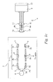
- the switch arrangement 1 further comprises a powered drive mechanism 12 for causing linear movement of the circuit breaker 4, in the terminal 3, between a first position illustrated in Figure 1a and a second position shown in Figure 1b .
- the first contact 10 slideably engages the bus-bar contact 5 and the second contact 11 slideably engages the cable contact 6.
- the bus-bar 8 is electrically connected via the breaker 4 to the cable contact 6 so that the switch gear arrangement 1 can supply power to a load (not shown).
- the circuit breaker 4 is in the first position but it is open (i.e. the internal contacts 4a are open) the bus-bar 8 is electrically disconnected by the breaker 4 from the cable contact 6 and the switch gear arrangement 1 cannot supply power to the load (not shown).
- the first contact 10 slideably engages the cable contact 6 and the second contact 11 slideable engages the earth contact 7.
- the cable contact 6 is electrically disconnected from the bus-bar 8 and from the earth contact 7.
- the cable contact 6 is electrically disconnected from the bus-bar 8, but is electrically connected to earth via the circuit breaker 4. In one or other of these configurations of the second position, maintenance or testing of components can be performed.
- Figure 1c illustrates the circuit breaker 4 in a third position in which it is withdrawn from the switch gear arrangement 1.
- the circuit breaker 4 may be driven between this position and the second position along the axis A by the drive mechanism 12.
- the circuit breaker 4 and the drive mechanism 12 may be constructed as an integrated unit, which a human operator can manipulate manually between the second and third positions or can be power driven between the second and third positions.
- a shutter 13 is provided, which can be drawn into the position shown in Figure1 1b , as a physical barrier between the bus bar contact 5 and the breaker 4, so that tests can be performed on the breaker.
- the housing may be transparent to allow for easy visible inspection of components.
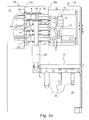
- Figures 3a to 3c illustrate a side view of the inside of a cabinet 20, housing a medium voltage electrical switchgear 2 embodying the present invention.
- Figure 3d illustrates a perspective view of the inside of the cabinet 20.
- Features the same as those already described with respect to Figures 1a to 1c are given the same reference numerals in Figures 3a to 3d as they are in Figures 1a to 1c .
- the cabinet 20 is divided by internal partitions 25 into a plurality of compartments 21 to 24 containing the internal components of the switchgear 2.
- the switchgear 2 is a three-phase system and so comprises three conductive busbars 8 in an upper rearward section 21.
- Each busbar 8 is provided with a terminal 3, of the type illustrated in Figures 2a to 2c , which extends from the upper rearward compartment 21, across an upper middle compartment 22, to an upper forward compartment 23.
- a circuit breaker 4 also of the type illustrated in Figures 2a to 2c , is associated with each terminal 3.
- each terminal's 3 first tubular section 3a is partly in the upper rearward compartment 21 and partly in the upper middle compartment 22 and extends through the partition 25a which divides these two compartments; each terminal's 3 second tubular section 3b is supported in the upper middle compartment 22; and each terminal's 3 third tubular section 3c is in the upper forward section 23 and defines an aperture (best seen in Figure 3c ) through the partition 25b separating the upper forward section 23 and the upper middle section 22.
- a bottom compartment 24 contains three groups of three cable terminations 26 (only one group of the three is visible in Figures 3a to 3c ) which are connectable to cables (not shown) routed to a load (not shown).
- Each group of three cable terminations 26 is connected to a respective one of three conductors 27, which is routed to a cable contact 6 of a respective one of the terminals 3.
- Each conductor 27 may be fitted with measuring equipment 28, for example, a current transformer, voltage transformer or other such device.
- a drive means 12 for driving each circuit breaker 4 between the first position illustrated in Figure 3a (and Figure 1a ) and the second position illustrated in Figure 3b (and Figure 2b ) is contained in the upper forward compartment 23.
- the drive means 12 comprises a power driven carrier unit 29 mounted on a rail system 29a (see Figure 3d ) which supports the breakers 4, and is driven back and forth on the rail system to move the breakers 4, in unison, between the first and second positions. As explained above, the movement of the breakers 4 is substantially linear.
- each bus bar 8 is connected to a respective one of the three groups of cable termination 26 via a bus bar contact 5, a breaker 4, a cable contact 6 and a conductor 27.
- each group of three cable termination 26 is connected to an earth connection via a respective conductor 27, a respective cable contact 6, a respective breaker 4, and a respective earth contact 7.
- the earth contact 7 is connected to the earth connection 30 via partition 25b and the metal cabinet 20.
- Figure 3c illustrates the third position in which the breakers 4 are withdrawn from the switch gear assembly.
- the breakers 4 and the drive means 12 form an integrated unit which is easily removeable from the switchgear 2.
- the terminals 3 are arranged in parallel within the cabinet 20 diagonally relative to the sides of the cabinet, with the breakers 4 correspondingly arranged. This provides for a more compact arrangement than could be achieved by arranging the terminals 3 and breakers 4 horizontally or vertically.
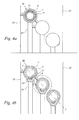
- FIG 4a illustrates a cross sectional view through the second sections 3b of the three terminals 3 viewed front on (although for simplicity, internal details, which are same for all three sections, are illustrated only in one). It can be seen that each housing section 3b has a cross section, in a plane substantially perpendicular to its longitudinal axis (i.e. the axis perpendicular to the plane of the page), that is substantially circular.
- Figure 4a shows each housing section 3b with a breaker 4 inserted therein, in the first position.
- each cable contact 6 is a conductive tube or a ring inserted in the housing section 3b and is coaxial with the housing section 3b.
- the inner radius of each housing section 3b and the outer radius of each cable contact 6 are substantially the same so each cable contact 6 fits snugly in a housing section 3b.
- Each breaker 4 is generally cylindrical in shape and its first and second 11 contacts (only the second contacts 11 are visible in Figure 4a ) are metal coils each located in a respective annular groove (not shown) that extends around an external diameter of the breaker 4.
- the fit between the terminal contacts and the external breaker contacts 11 is such that the breaker 4 can be slid in the housing between the first and second positions.
- a distance x is maintained between adjacent ones of the switching arrangements of the three different phases and between each of the switching arrangements of the two outer phases and earth.
- FIG 4b illustrates a cross section through the second sections 3b' of three terminals 3' viewed front on, in which terminals 3' the terminal contacts are arranged differently to those described above.
- each second section 3b' comprises a recess 40 formed in its inner surface and a cable contact 6' is located in the recess 40.
- the recess 40 and its associated contact 6' extend partially around a circumference of the inner wall, in this example, defining a segment that subtends an angle of approximately 30 degrees with the centre of the second section 3b'.
- each contact 7' is a strip having a slightly curved upper surface that is flush with the inner wall of the second section 3b.
- the thickness of a second section 3b' may vary around its circumference, being thicker in the region around a contact 7'. This additional thickness increases the rigidity of the section 3b' around the contact. This may be advantageous if for the example the contact 7' is formed of a relatively heavy metal like copper, rather than a lighter metal like aluminium.
- each second section 3b' has a cross section that is generally oval in shape, although it may instead be circular or indeed some other shape.
- each terminal 3' comprises first and third sections that correspond with the sections 3a and 3b described above, except that the cross sectional shape of the sections and the arrangement of the terminal contacts therein correspond with the arrangement of Figure 4b .
- Each breaker 4' comprises at its respective ends, first and second 11' external electrical contacts (only the second is illustrated in Figure 4b ), each of which extends partially around the external diameter of the breaker 4' and has a width and length that substantially matches those of the housing contacts.
- Locating a terminal contact in a recess formed in the inner wall of the housing means that the diameter of the cavity defined by inner wall can be reduced because it does not need to accommodate the terminal contact.
- reducing the diameter of the cavity means that the diameter of the terminal can likewise be reduced (over much of the circumference of terminal, if not all of it) which provides for a more compact terminal.
- the terminals are arranged substantially in parallel in the switchgear and are spaced apart along a diagonal line Y-Y. This is a particularly space efficient arrangement.
- the terminals may also have alternative spatial arrangements, for example, arranged in a horizontal or vertical line and still provide for more space efficient switchgears.
- a switchgear comprising a single terminal may be made more compact than one also comprising a single terminal but having a traditional circular cross section.
- the described terminal housing is in three distinct separate sections, it may instead be a single unitary housing with the contacts 5, 6, 7 being spaced apart along its length and electrically isolated from each other.
- the housing may comprise two distinct sections with one of the contacts, say the bus bar contact 5, in one section, and the other two contacts in the other section.
- the switch arrangement is configured for use in the three positions of Figures 2a to 2c this is not essential.
- Alternative embodiments may comprise a single operative position(e.g. a service position) or two positions, (e.g. a service position and a withdrawn position, or a service position and an earth position).
- the general shape of the housing and of the breaker may of course vary from that described above.
Landscapes
- Engineering & Computer Science (AREA)
- Power Engineering (AREA)
- Gas-Insulated Switchgears (AREA)
Priority Applications (19)
| Application Number | Priority Date | Filing Date | Title |
|---|---|---|---|
| EP10002053A EP2363930A1 (de) | 2010-03-01 | 2010-03-01 | Schaltanordnung für eine elektrische Schaltanlage |
| CN2011800221333A CN102870297A (zh) | 2010-03-01 | 2011-03-01 | 用于电气开关设备的端子 |
| CA2791554A CA2791554A1 (en) | 2010-03-01 | 2011-03-01 | A switch arrangement for an electrical switchgear |
| AU2011223278A AU2011223278B2 (en) | 2010-03-01 | 2011-03-01 | A switch arrangement for an electrical switchgear |
| CN2011800221507A CN102884687A (zh) | 2010-03-01 | 2011-03-01 | 用于电气开关设备的开关装置 |
| US13/582,152 US9177730B2 (en) | 2010-03-01 | 2011-03-01 | Terminal for an electrical switchgear |
| DK11711445.4T DK2543121T3 (da) | 2010-03-01 | 2011-03-01 | En omstillingsanordning til et elektrisk fordelingsanlæg |
| PCT/EP2011/000994 WO2011107255A1 (en) | 2010-03-01 | 2011-03-01 | A switch arrangement for an electrical switchgear |
| PCT/EP2011/000992 WO2011107254A1 (en) | 2010-03-01 | 2011-03-01 | A terminal for an electrical switchgear |
| PL11711445T PL2543121T3 (pl) | 2010-03-01 | 2011-03-01 | Zespół wyłącznika do elektrycznej aparatury rozdzielczej |
| EP11711445.4A EP2543121B1 (de) | 2010-03-01 | 2011-03-01 | Schaltanordnung für eine elektrische schaltanlage |
| DK11710121.2T DK2543120T3 (da) | 2010-03-01 | 2011-03-01 | Terminal til et elektrisk fordelingsanlæg |
| ES11711445.4T ES2523279T3 (es) | 2010-03-01 | 2011-03-01 | Una disposición de interrupción para un aparellaje eléctrico |
| RU2012141654/07A RU2558391C2 (ru) | 2010-03-01 | 2011-03-01 | Компоновка переключателя для электрического распределительного устройства |
| UAA201211290A UA105842C2 (uk) | 2010-03-01 | 2011-03-01 | Компонування перемикача для електричного розподільного пристрою |
| EP11710121.2A EP2543120B1 (de) | 2010-03-01 | 2011-03-01 | Schaltanordnung für eine elektrische Schaltanlage |
| PL11710121T PL2543120T3 (pl) | 2010-03-01 | 2011-03-01 | Zacisk do elektrycznej aparatury rozdzielczej |
| US13/581,889 US9153390B2 (en) | 2010-03-01 | 2011-03-01 | Switch arrangement for an electrical switchgear |
| BR112012022193A BR112012022193A2 (pt) | 2010-03-01 | 2011-03-01 | arranjo de disjuntor para um equipamento de manobra elétrica e equipamento de manobra |
Applications Claiming Priority (1)
| Application Number | Priority Date | Filing Date | Title |
|---|---|---|---|
| EP10002053A EP2363930A1 (de) | 2010-03-01 | 2010-03-01 | Schaltanordnung für eine elektrische Schaltanlage |
Publications (1)
| Publication Number | Publication Date |
|---|---|
| EP2363930A1 true EP2363930A1 (de) | 2011-09-07 |
Family
ID=42342457
Family Applications (1)
| Application Number | Title | Priority Date | Filing Date |
|---|---|---|---|
| EP10002053A Withdrawn EP2363930A1 (de) | 2010-03-01 | 2010-03-01 | Schaltanordnung für eine elektrische Schaltanlage |
Country Status (1)
| Country | Link |
|---|---|
| EP (1) | EP2363930A1 (de) |
Cited By (1)
| Publication number | Priority date | Publication date | Assignee | Title |
|---|---|---|---|---|
| CN113412004A (zh) * | 2020-03-17 | 2021-09-17 | Abb瑞士股份有限公司 | 用于低压和中压应用的电气开关设备 |
Citations (2)
| Publication number | Priority date | Publication date | Assignee | Title |
|---|---|---|---|---|
| US3899722A (en) * | 1973-07-12 | 1975-08-12 | Bbc Brown Boveri & Cie | Plastics-insulated switch unit for multi-phase high-voltage switchgear installations with earthing contact |
| DE4445172A1 (de) * | 1994-12-17 | 1996-06-20 | Abb Patent Gmbh | Schaltfeld |
-
2010
- 2010-03-01 EP EP10002053A patent/EP2363930A1/de not_active Withdrawn
Patent Citations (2)
| Publication number | Priority date | Publication date | Assignee | Title |
|---|---|---|---|---|
| US3899722A (en) * | 1973-07-12 | 1975-08-12 | Bbc Brown Boveri & Cie | Plastics-insulated switch unit for multi-phase high-voltage switchgear installations with earthing contact |
| DE4445172A1 (de) * | 1994-12-17 | 1996-06-20 | Abb Patent Gmbh | Schaltfeld |
Cited By (1)
| Publication number | Priority date | Publication date | Assignee | Title |
|---|---|---|---|---|
| CN113412004A (zh) * | 2020-03-17 | 2021-09-17 | Abb瑞士股份有限公司 | 用于低压和中压应用的电气开关设备 |
Similar Documents
| Publication | Publication Date | Title |
|---|---|---|
| EP2543121B1 (de) | Schaltanordnung für eine elektrische schaltanlage | |
| US8248760B2 (en) | Switch arrangement for an electrical switchgear | |
| EP2485348A2 (de) | Schaltanlage | |
| JP4727736B2 (ja) | スイッチギヤ | |
| US8525053B2 (en) | Electrical switchgear | |
| US20020104827A1 (en) | Gas insulated switchgear | |
| EP2017866A1 (de) | Vakuumisoliertes Schaltgetriebe | |
| EP3671989B1 (de) | Dreiphasen-schaltanlage mit einphasiger ausrüstung in einem gehäuse | |
| US11005240B2 (en) | Three phase switchgear or control gear | |
| EP3336870B1 (de) | Gis mit einem trenner/erdungsschalter | |
| HU189964B (en) | Metal-clad gas-insulation switching apparatus | |
| US7692113B2 (en) | Switch assembly | |
| EP2363931A1 (de) | Schaltanordnung für eine elektrische Schaltanlage | |
| CN113412004B (zh) | 用于低压和中压应用的电气开关设备 | |
| EP2363932A1 (de) | Schaltanordnung für eine elektrische Schaltanlage | |
| EP1768149B1 (de) | Schaltanlage für Mehrfachkreise | |
| CN113346398A (zh) | 用于低电压和中电压应用的电气开关装置 |
Legal Events
| Date | Code | Title | Description |
|---|---|---|---|
| PUAI | Public reference made under article 153(3) epc to a published international application that has entered the european phase |
Free format text: ORIGINAL CODE: 0009012 |
|
| AK | Designated contracting states |
Kind code of ref document: A1 Designated state(s): AT BE BG CH CY CZ DE DK EE ES FI FR GB GR HR HU IE IS IT LI LT LU LV MC MK MT NL NO PL PT RO SE SI SK SM TR |
|
| AX | Request for extension of the european patent |
Extension state: AL BA ME RS |
|
| STAA | Information on the status of an ep patent application or granted ep patent |
Free format text: STATUS: THE APPLICATION IS DEEMED TO BE WITHDRAWN |
|
| 18D | Application deemed to be withdrawn |
Effective date: 20120308 |