EP2364247B1 - Dispositif et procédé de fabrication de conteneurs en forme de tube - Google Patents
Dispositif et procédé de fabrication de conteneurs en forme de tube Download PDFInfo
- Publication number
- EP2364247B1 EP2364247B1 EP09771695A EP09771695A EP2364247B1 EP 2364247 B1 EP2364247 B1 EP 2364247B1 EP 09771695 A EP09771695 A EP 09771695A EP 09771695 A EP09771695 A EP 09771695A EP 2364247 B1 EP2364247 B1 EP 2364247B1
- Authority
- EP
- European Patent Office
- Prior art keywords
- workstation
- mandrel
- mandril
- group
- groups
- Prior art date
- Legal status (The legal status is an assumption and is not a legal conclusion. Google has not performed a legal analysis and makes no representation as to the accuracy of the status listed.)
- Active
Links
Images


Classifications
-
- B—PERFORMING OPERATIONS; TRANSPORTING
- B29—WORKING OF PLASTICS; WORKING OF SUBSTANCES IN A PLASTIC STATE IN GENERAL
- B29C—SHAPING OR JOINING OF PLASTICS; SHAPING OF MATERIAL IN A PLASTIC STATE, NOT OTHERWISE PROVIDED FOR; AFTER-TREATMENT OF THE SHAPED PRODUCTS, e.g. REPAIRING
- B29C43/00—Compression moulding, i.e. applying external pressure to flow the moulding material; Apparatus therefor
- B29C43/02—Compression moulding, i.e. applying external pressure to flow the moulding material; Apparatus therefor of articles of definite length, i.e. discrete articles
- B29C43/04—Compression moulding, i.e. applying external pressure to flow the moulding material; Apparatus therefor of articles of definite length, i.e. discrete articles using movable moulds
-
- B—PERFORMING OPERATIONS; TRANSPORTING
- B29—WORKING OF PLASTICS; WORKING OF SUBSTANCES IN A PLASTIC STATE IN GENERAL
- B29C—SHAPING OR JOINING OF PLASTICS; SHAPING OF MATERIAL IN A PLASTIC STATE, NOT OTHERWISE PROVIDED FOR; AFTER-TREATMENT OF THE SHAPED PRODUCTS, e.g. REPAIRING
- B29C31/00—Handling, e.g. feeding of the material to be shaped, storage of plastics material before moulding; Automation, i.e. automated handling lines in plastics processing plants, e.g. using manipulators or robots
- B29C31/002—Handling tubes, e.g. transferring between shaping stations, loading on mandrels
-
- B—PERFORMING OPERATIONS; TRANSPORTING
- B29—WORKING OF PLASTICS; WORKING OF SUBSTANCES IN A PLASTIC STATE IN GENERAL
- B29C—SHAPING OR JOINING OF PLASTICS; SHAPING OF MATERIAL IN A PLASTIC STATE, NOT OTHERWISE PROVIDED FOR; AFTER-TREATMENT OF THE SHAPED PRODUCTS, e.g. REPAIRING
- B29C33/00—Moulds or cores; Details thereof or accessories therefor
- B29C33/34—Moulds or cores; Details thereof or accessories therefor movable, e.g. to or from the moulding station
-
- B—PERFORMING OPERATIONS; TRANSPORTING
- B29—WORKING OF PLASTICS; WORKING OF SUBSTANCES IN A PLASTIC STATE IN GENERAL
- B29C—SHAPING OR JOINING OF PLASTICS; SHAPING OF MATERIAL IN A PLASTIC STATE, NOT OTHERWISE PROVIDED FOR; AFTER-TREATMENT OF THE SHAPED PRODUCTS, e.g. REPAIRING
- B29C43/00—Compression moulding, i.e. applying external pressure to flow the moulding material; Apparatus therefor
- B29C43/02—Compression moulding, i.e. applying external pressure to flow the moulding material; Apparatus therefor of articles of definite length, i.e. discrete articles
- B29C43/04—Compression moulding, i.e. applying external pressure to flow the moulding material; Apparatus therefor of articles of definite length, i.e. discrete articles using movable moulds
- B29C43/06—Compression moulding, i.e. applying external pressure to flow the moulding material; Apparatus therefor of articles of definite length, i.e. discrete articles using movable moulds continuously movable in one direction, e.g. mounted on chains, belts
- B29C43/08—Compression moulding, i.e. applying external pressure to flow the moulding material; Apparatus therefor of articles of definite length, i.e. discrete articles using movable moulds continuously movable in one direction, e.g. mounted on chains, belts with circular movement, e.g. mounted on rolls, turntables
-
- B—PERFORMING OPERATIONS; TRANSPORTING
- B29—WORKING OF PLASTICS; WORKING OF SUBSTANCES IN A PLASTIC STATE IN GENERAL
- B29C—SHAPING OR JOINING OF PLASTICS; SHAPING OF MATERIAL IN A PLASTIC STATE, NOT OTHERWISE PROVIDED FOR; AFTER-TREATMENT OF THE SHAPED PRODUCTS, e.g. REPAIRING
- B29C43/00—Compression moulding, i.e. applying external pressure to flow the moulding material; Apparatus therefor
- B29C43/02—Compression moulding, i.e. applying external pressure to flow the moulding material; Apparatus therefor of articles of definite length, i.e. discrete articles
- B29C43/04—Compression moulding, i.e. applying external pressure to flow the moulding material; Apparatus therefor of articles of definite length, i.e. discrete articles using movable moulds
- B29C2043/046—Compression moulding, i.e. applying external pressure to flow the moulding material; Apparatus therefor of articles of definite length, i.e. discrete articles using movable moulds travelling between different stations, e.g. feeding, moulding, curing stations
-
- B—PERFORMING OPERATIONS; TRANSPORTING
- B29—WORKING OF PLASTICS; WORKING OF SUBSTANCES IN A PLASTIC STATE IN GENERAL
- B29C—SHAPING OR JOINING OF PLASTICS; SHAPING OF MATERIAL IN A PLASTIC STATE, NOT OTHERWISE PROVIDED FOR; AFTER-TREATMENT OF THE SHAPED PRODUCTS, e.g. REPAIRING
- B29C43/00—Compression moulding, i.e. applying external pressure to flow the moulding material; Apparatus therefor
- B29C43/32—Component parts, details or accessories; Auxiliary operations
- B29C2043/3272—Component parts, details or accessories; Auxiliary operations driving means
- B29C2043/3283—Component parts, details or accessories; Auxiliary operations driving means for moving moulds or mould parts
- B29C2043/3288—Component parts, details or accessories; Auxiliary operations driving means for moving moulds or mould parts using cam drives
-
- B—PERFORMING OPERATIONS; TRANSPORTING
- B29—WORKING OF PLASTICS; WORKING OF SUBSTANCES IN A PLASTIC STATE IN GENERAL
- B29C—SHAPING OR JOINING OF PLASTICS; SHAPING OF MATERIAL IN A PLASTIC STATE, NOT OTHERWISE PROVIDED FOR; AFTER-TREATMENT OF THE SHAPED PRODUCTS, e.g. REPAIRING
- B29C43/00—Compression moulding, i.e. applying external pressure to flow the moulding material; Apparatus therefor
- B29C43/32—Component parts, details or accessories; Auxiliary operations
- B29C43/36—Moulds for making articles of definite length, i.e. discrete articles
- B29C43/361—Moulds for making articles of definite length, i.e. discrete articles with pressing members independently movable of the parts for opening or closing the mould, e.g. movable pistons
- B29C2043/3615—Forming elements, e.g. mandrels or rams or stampers or pistons or plungers or punching devices
- B29C2043/3621—Forming elements, e.g. mandrels or rams or stampers or pistons or plungers or punching devices a plurality of individual elements acting on the material in the same or diferent directions, e.g. making tubular T-joints, profiles
- B29C2043/3623—Forming elements, e.g. mandrels or rams or stampers or pistons or plungers or punching devices a plurality of individual elements acting on the material in the same or diferent directions, e.g. making tubular T-joints, profiles coupled on a support, e.g. plate
-
- B—PERFORMING OPERATIONS; TRANSPORTING
- B29—WORKING OF PLASTICS; WORKING OF SUBSTANCES IN A PLASTIC STATE IN GENERAL
- B29C—SHAPING OR JOINING OF PLASTICS; SHAPING OF MATERIAL IN A PLASTIC STATE, NOT OTHERWISE PROVIDED FOR; AFTER-TREATMENT OF THE SHAPED PRODUCTS, e.g. REPAIRING
- B29C43/00—Compression moulding, i.e. applying external pressure to flow the moulding material; Apparatus therefor
- B29C43/02—Compression moulding, i.e. applying external pressure to flow the moulding material; Apparatus therefor of articles of definite length, i.e. discrete articles
- B29C43/18—Compression moulding, i.e. applying external pressure to flow the moulding material; Apparatus therefor of articles of definite length, i.e. discrete articles incorporating preformed parts or layers, e.g. compression moulding around inserts or for coating articles
-
- B—PERFORMING OPERATIONS; TRANSPORTING
- B29—WORKING OF PLASTICS; WORKING OF SUBSTANCES IN A PLASTIC STATE IN GENERAL
- B29K—INDEXING SCHEME ASSOCIATED WITH SUBCLASSES B29B, B29C OR B29D, RELATING TO MOULDING MATERIALS OR TO MATERIALS FOR MOULDS, REINFORCEMENTS, FILLERS OR PREFORMED PARTS, e.g. INSERTS
- B29K2105/00—Condition, form or state of moulded material or of the material to be shaped
- B29K2105/25—Solid
- B29K2105/253—Preform
- B29K2105/258—Tubular
-
- B—PERFORMING OPERATIONS; TRANSPORTING
- B29—WORKING OF PLASTICS; WORKING OF SUBSTANCES IN A PLASTIC STATE IN GENERAL
- B29L—INDEXING SCHEME ASSOCIATED WITH SUBCLASS B29C, RELATING TO PARTICULAR ARTICLES
- B29L2001/00—Articles provided with screw threads
-
- B—PERFORMING OPERATIONS; TRANSPORTING
- B29—WORKING OF PLASTICS; WORKING OF SUBSTANCES IN A PLASTIC STATE IN GENERAL
- B29L—INDEXING SCHEME ASSOCIATED WITH SUBCLASS B29C, RELATING TO PARTICULAR ARTICLES
- B29L2023/00—Tubular articles
- B29L2023/20—Flexible squeeze tubes, e.g. for cosmetics
-
- B—PERFORMING OPERATIONS; TRANSPORTING
- B29—WORKING OF PLASTICS; WORKING OF SUBSTANCES IN A PLASTIC STATE IN GENERAL
- B29L—INDEXING SCHEME ASSOCIATED WITH SUBCLASS B29C, RELATING TO PARTICULAR ARTICLES
- B29L2031/00—Other particular articles
- B29L2031/712—Containers; Packaging elements or accessories, Packages
-
- Y—GENERAL TAGGING OF NEW TECHNOLOGICAL DEVELOPMENTS; GENERAL TAGGING OF CROSS-SECTIONAL TECHNOLOGIES SPANNING OVER SEVERAL SECTIONS OF THE IPC; TECHNICAL SUBJECTS COVERED BY FORMER USPC CROSS-REFERENCE ART COLLECTIONS [XRACs] AND DIGESTS
- Y10—TECHNICAL SUBJECTS COVERED BY FORMER USPC
- Y10T—TECHNICAL SUBJECTS COVERED BY FORMER US CLASSIFICATION
- Y10T156/00—Adhesive bonding and miscellaneous chemical manufacture
- Y10T156/17—Surface bonding means and/or assemblymeans with work feeding or handling means
Definitions
- the invention relates to a device for producing tubes according to the preamble of claim 1 and to a method for producing tubes according to the preamble of claim 11.
- Known devices for producing plastic tubes have a plurality of mandrel assemblies fixedly arranged on a rotatable table, each comprising a plurality of mandrels on which the tubes are produced stepwise at workstations distributed over the circumference of the rotatable table.
- Each workstation has in this case a number of tools corresponding to the number of mandrels of a mandrel arrangement in order to be able to produce the tubes simultaneously on all mandrels of a mandrel arrangement.
- a disadvantage of the known devices are the high investment costs.
- Domkarussell is known in which mandrel assemblies are fixedly mounted on an index disc and can be transported from workstation to workstation. Furthermore, it is known that each mandrel assembly consists of two identical mandrel groups fixedly arranged on the indexing disc, which are diametrically opposed with respect to the axis of rotation of the indexing disc and are not adjustable at a workstation relative to the indexing disc.
- the DE 40 09 661 C1 shows a mandrel carousel, in which mandrel assemblies are in their entirety relative to the index disc to cooperate with laterally arranged the index disc presses can.
- the invention has for its object to provide a cost-effective device for the manufacture of tubes. Furthermore, the object is to propose an optimized method for producing tubes, which allows the use of cost-effective manufacturing devices. Preferably, the throughput of manufacturable tubes should not be adversely affected.
- the invention makes use of the knowledge that at least two work steps to be carried out at workstations spaced apart from one another take different lengths of time during the production of the tubes on the mandrels.
- work steps such as loading and unloading the mandrels only half the cycle time is required as for other process steps such as the pressing of the tube shoulder.
- the step of setting the tube shoulder on the tube body is the most time-consuming process step.
- the other, faster operating workstations stand still for a comparatively large period of time during the at least one longer working step.
- At least two arbor groups of a mandrel assembly can be processed successively, respectively in the processing position at a workstation, preferably in the time, the slowest workstation for processing the tubes on another mandrel assembly, preferably for the simultaneous Processing all tubes this mandrel assembly needed or takes the most time-consuming step.
- the number of tools of the two mandrel groups successively processing workstation can be halved, in the case of the provision of three mandrel groups, be reduced to one-third, etc.
- all mandrel groups of the at least one mandrel arrangement have the same number of thorns.
- the realization of a relative adjustability of the mandrel groups of at least one mandrel arrangement relative to the movement path of the mandrel assemblies from workstation to workstation or to the transport means for the mandrel assemblies allows the reduction of tools on at least one workstation, as not all mandrel groups simultaneously, but at least two Mandrel groups of a mandrel assembly can be processed sequentially.
- the throughput of the device is not adversely affected.
- the mandrel arrangement can also be adjusted by rotation, so that the mandrel groups of the mandrel arrangement are adjustable relative to the workstation, preferably by rotating the entire mandrel assembly, in a rotational movement between the associated processing position and the parking position.
- the mandrel groups from workstation to workstation on a (except for the Auslenkschulen the mandrel groups) circular trajectory are transportable relative to the mandrel groups are adjustable at least one workstation.
- an embodiment can be realized in which the mandrel groups at least partially translationally from workstation to workstation are transported, wherein also in this embodiment, the mandrel assemblies are preferably performed in a circuit.
- the mandrel arrangements are arranged on a rotatable table (transport means) relative to which at least the mandrel groups of a mandrel arrangement are adjustable. If at least one mandrel arrangement, preferably all mandrel arrangements, are not arranged statically, as in the prior art, on a rotatable table, but adjustable relative thereto.
- the table is preferably rotatably driven by means of a servomotor or alternatively a stepping gear.
- the adjustment movement of the first and the second mandrel group is realized as a movement guided by a cam, wherein the cam plate is preferably rotatable relative to the table or to the movement path of the mandrel arrangements from workstation to workstation.
- a cam preferably rotatable relative to the table or to the movement path of the mandrel arrangements from workstation to workstation.
- the cam disc is moved in a transport of the mandrel assemblies from workstation to workstation in a first direction, preferably in the transport direction of the mandrel assemblies.
- this movement of the cam in the first direction is designed such that in this case there is no relative movement of the cam to the mandrel arrangements.
- the cam is driven in a second direction, which is opposite to the first direction, in particular the transport direction.
- the adjusting movement of the cam takes place in this second direction when the work equipment is stationary, preferably when the table is stationary, ie when the mandrel arrangements not be transported from workstation to workstation.
- the cam plate is preferably movable in the manner of a ratchet alternately in a first and a second, the first direction opposite direction, preferably such that during the adjustment in the first direction no relative movement between the cam and the mandrel assemblies is realized, but only to be adjusted during the adjustment in the second direction to the mandrel groups only when the table is stationary, preferably translationally, between the associated processing position and the associated parking position.
- the parking position of the first and / or the second mandrel group at one of the workstations of the processing position of another, preferably the adjacent in the direction of movement workstation corresponds to ensure that each tube blank before the next processing step sufficient Rest period can be maintained.
- one of the workstations, relative to which the mandrel arrangements are adjustable by means of the transport means is an unloading station.
- it is not an unloading station, but a Umladestation for reloading the unfinished tubes on other mandrels, which are adjustable by means of a transport means arranged adjacent to the transport means between other workstations.
- both the means of transport and the transport device each comprise a rotatable table.
- the still unfinished tubes are transported by means of the transport device to at least one cover assembly station on which a cover, preferably by twisting the cover, is mounted on an external thread in the region of a tube outlet.
- the invention also leads to a method for producing tubes, in particular plastic tubes, and / or at least one foil having at least one plastic layer, preferably using one after the Concept of the invention trained device.
- the core of the method is that not only the mandrel assemblies are transported from workstation to workstation but with at least one mandrel assembly, preferably all mandrel assemblies, given the possibility of mandrel grouping the at least one mandrel assembly in at least one workstation between a processing position in the mandrel assembly a mandrel group can interact with the workstation and a parking position is adjustable.
- the possibility of a relative movement of mandrel groups of at least one of the mandrel assemblies relative to the actual trajectory of the mandrel assembly is provided from workstation to workstation, so that at least one workstation not all mandrels of the at least one mandrel assembly, or the blanks thereon, simultaneously from the workstation must be processed, but that the mandrel groups of the mandrel assembly can be processed by the workstation successively.
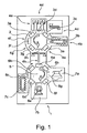
- Fig. 1 is a fragmentary view in a highly schematic view of an apparatus 1 for carrying out a method for producing tubes made of plastic.
- the apparatus 1 comprises rotatable transport means 2 for transporting mandrel assemblies 3a-3h from workstation 4a-4h to workstation 4a-4h.
- eight eight workstations 4a-4h are arranged around the means of transport 2.
- an optional workstation which may be formed, if necessary, for example, for equipping the mandrel assemblies 3a-3h with a shoulder protector and / or with inserts.
- the workstation 4b is a loading station, with which mandrel groups of the mandrel arrangements 3a-3h, which are still to be explained later, can be equipped successively with tubular tube bodies.
- the workstation identified by the reference numeral 4c is a combined extrusion / placement station in which the mandrels of the mandrel assemblies 3a-3h are fitted with extruded plastic rings.
- the circumferentially adjacent workstation identified by the reference numeral 4d it is a compression station, in which formed from the previously stocked plastic rings tube shoulders with molded outlets and simultaneously be molded to the tube body.
- the three adjacent workstations 4e, 4f and 4g are cooling stations in which the shoulders with the outlets formed thereon are cooled with the aid of fans and / or internal mandrel cooling.
- the seventh, characterized by the reference numeral 4h workstation is a transfer station, are removed with the unfinished tubes from the transport means 2 and the mandrel assemblies 3a-3h of the transport 2 and reloaded onto a transport device 5 and on mandrel packages 6a-6g.
- the mandrel packages 6 are moved between further workstations 7a-7c, wherein the workstation identified by the reference numeral 7a includes an optional sealing station, the work station designated by the reference numeral 7b a capping station and the workstation designated by the reference numeral 7c an unloading station is.
- Fig. 1 The number of mandrel assemblies 3a-3h corresponds to the number of mandrel packages 6. Also, the number of mandrels, not shown, of mandrel assemblies 3a-3h corresponds to the number of mandrels of mandrel packages 6.
- the transport means 2 rotate in a direction opposite to the direction of rotation of the transport device 5, here in the counterclockwise direction.
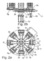
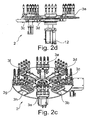
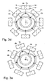
- Fig. 2a to 2d show in different, partly perspective views of the structure of the transport means 2 and the mandrel assemblies 3a-3h.
- each mandrel assembly 3a-3h two groups of thorns 8, namely a first mandrel group 9 and a stationary relative to This arranged second mandrel group 10.
- Both mandrel groups 9, 10 have the same number of thorns 8, here four mandrels 8, on.
- the mandrels 8 of the two groups of mandrels 9, 10 are each arranged as a row of mandrels, wherein the rows of mandrels extend tangentially to the direction of movement of the mandrel assemblies 3a-3h from workstation 4a-4h to workstation 4a-4h.
- Each mandrel assembly 3a-3h is in turn mounted on guide rails 11 on which the mandrel assemblies 3a-3h can be adjusted relative to the circular path of movement on which the mandrel assemblies 3a-3h are adjustable from workstation to workstation.
- the corresponding mandrel arrangements 3a-3h relative to the transport means 2 more precisely relative to a table 13 rotatably driven by means of a servomotor 12, adjusted.
- cam disc 14 is provided which is driven by means of a servomotor 12 designed as a servomotor 15 via a belt 16.
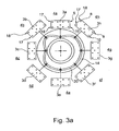
- the mandrel groups 9, 10 of each corresponding mandrel assembly 3a-3h can be interposed between a machining position in which the work station can interact with the respective mandrel group 9, 10 and one park position, respectively the workstation can not interfere with the corresponding mandrel group.
- this is the case at the mandrel arrangement designated by the reference symbol 3a Fig. 2a explained.
- this mandrel assembly 3a is the second mandrel group 10, that is, the radially inner row of mandrels 8, in a processing position 17, in which the non-illustrated workstation with the second mandrel group 10 can interact.
- the first mandrel group 9 is located in a first parking position 18, in which the non-illustrated workstation can not interact with the spikes 8 of the first mandrel group 9.
- the mandrel assembly 3 is translationally relative to the transport means 2 such moved radially inward, that the first mandrel group 9 enters the processing position 17, in which the workstation, not shown, with the first mandrel group 9 can interact.
- the second mandrel group 10 previously stationed in the (common) processing position 17 is then located in a radially inner, second parking position 19 in which the workstation can not interact with the second mandrel group 10.
- the two mandrel groups 9, 10 of a mandrel arrangement 3a-3h are assigned a common processing position 17 and their own parking position 18, 19 respectively.
- the cam 14 was counterclockwise 45 ° counterclockwise between the in the Fig. 3a and Fig. 3d adjusted states shown.
- the respective other mandrel groups of the mandrel arrangements 3a, 3b, 3c, 3h can be processed.
- the second mandrel group 10 of the mandrel group 3a is now in the processing position 17, whereas the first mandrel group 9 of the mandrel assembly 3a has been translationally adjusted into the radially outer parking position 18.
- the mandrel arrangements 3a-3h must now be adjusted in the circumferential direction along a circular movement path to the next workstation 4b, 4c, 4d, 4f, 4g, 4h, 4a.
- the transport means 2 are adjusted in synchronism with the cam 14 by 45 ° in the counterclockwise direction, so that the cam 14, the in Fig. 3f position reproduced by the way Fig. 3a corresponds shown position.
- Fig. 3e shows an intermediate movement state of the mandrel assemblies 3a-3h on their way to the next workstation 4b, 4c, 4d, 4e, 4f, 4g, 4h, 4a.
Landscapes
- Engineering & Computer Science (AREA)
- Mechanical Engineering (AREA)
- Robotics (AREA)
- Shaping Of Tube Ends By Bending Or Straightening (AREA)
- Automatic Assembly (AREA)
- Container, Conveyance, Adherence, Positioning, Of Wafer (AREA)
Abstract
Claims (15)
- Dispositif de fabrication de tubes, comprenant plusieurs agencements de mandrins (3a-3h), comprenant à chaque fois plusieurs mandrins (8) sur lesquels les tubes peuvent être fabriqués par étapes sur plusieurs postes de travail (4a-4h), les agencements de mandrins (3a-3h) pouvant être transportés à l'aide de moyens de transport (2) d'un poste de travail à un autre,
caractérisé en ce que
les mandrins (8) d'au moins l'un des agencements de mandrins (3a-3h) sont divisés en un premier et au moins un deuxième groupe de mandrins (9, 10), et en ce que le premier groupe de mandrins (9), au moins dans l'un des postes de travail (4a-4h), peut être déplacé d'une position de traitement (17) associée au poste de travail, dans laquelle le poste de travail (4a-4h) peut entrer en interaction avec le premier groupe de mandrins (9), par rapport aux moyens de transport (2), dans une position de stationnement (18, 19) associée au poste de travail (4a-4h), et le deuxième groupe de mandrins (10) peut être déplacé d'une position de stationnement (18, 19) associée au poste de travail (4a-4h) dans une position de traitement (17) associée au poste de travail, par rapport aux moyens de transport (2). - Dispositif selon la revendication 1,
caractérisé en ce que
l'au moins un poste de travail (4a-4h), au niveau duquel le premier et le deuxième groupe de mandrins (9, 10) peuvent être déplacés, présente un nombre d'outils correspondant au nombre de mandrins (8) du premier ou du deuxième groupe de mandrins (9, 10). - Dispositif selon l'une quelconque des revendications 1 ou 2,
caractérisé en ce que
le premier et le deuxième groupe de mandrins (9, 10) peuvent être déplacés simultanément entre la position de traitement (17) et la position de stationnement (18, 19) respectivement entre la position de stationnement (18, 19) et la position de traitement (17). - Dispositif selon l'une quelconque des revendications précédentes,
caractérisé en ce que
le premier et le deuxième groupe de mandrins (9, 10) peuvent être déplacés par déplacement en translation de l'agencement de mandrins (3a-3h) présentant les groupes de mandrins (9, 10), entre la position de traitement respective (17) et la position de stationnement respective (18, 19). - Dispositif selon l'une quelconque des revendications précédentes,
caractérisé en ce que
les groupes de mandrins (9, 10) peuvent être transportés d'un poste de travail (4a-4h) à un autre (4a-4h) sur une voie de transport circulaire. - Dispositif selon la revendication 5,
caractérisé en ce que
les agencements de mandrins (3a-3h) sont disposés sur une table (13) rotative, de préférence au moyen d'un servomoteur (12), par rapport à laquelle le premier et le deuxième groupe de mandrins (9, 10) peuvent être déplacés au niveau d'au moins l'un des postes de travail (4a-4h). - Dispositif selon l'une quelconque des revendications 5 ou 6,
caractérisé en ce que
le mouvement de déplacement du premier et du deuxième groupe de mandrins (9, 10) entre la position de traitement (17) et la position de stationnement (18, 19) est un mouvement guidé au moyen d'un disque à cames (14). - Dispositif selon la revendication 7,
caractérisé en ce que
le disque à cames (14) dans le cas d'un transport des agencements de mandrins (3a-3h) d'un poste de travail (4a-4h) à un autre poste de travail (4a-4h), peut être tourné dans une première direction, de préférence dans la direction de transport des agencements de mandrins (3a-3h), et pour le déplacement du premier et du deuxième groupe de mandrins (9, 10) entre la position de traitement (17) et la position de stationnement (18, 19) ou entre la position de stationnement (18, 19) et la position de traitement (17), peut être tourné dans une deuxième direction opposée à la première direction. - Dispositif selon l'une quelconque des revendications précédentes,
caractérisé en ce
qu'une position de stationnement (18, 19) du premier et/ou du deuxième groupe de mandrins (9, 10) au niveau de l'un des postes de travail (4a-4h) correspond à la position de traitement (17) d'un autre poste de travail (4a-4h), de préférence au poste de travail le plus proche dans la direction de transport. - Dispositif selon l'une quelconque des revendications précédentes,
caractérisé en ce
qu'au moins l'un des postes de travail (4a-4h) est un poste de déchargement ou un poste de transfert pour transférer des tubes pas encore finis à des mandrins (8), qui peuvent être transportés au moyen d'un dispositif de transport (5) à au moins un autre poste de travail, de préférence à au moins un poste de montage de couvercle. - Procédé de fabrication de tubes, notamment utilisant un dispositif (1) selon l'une quelconque des revendications précédentes, dans lequel sont prévus plusieurs agencements de mandrins (3a-3h), comprenant à chaque fois plusieurs mandrins (8) sur lesquels les tubes peuvent être fabriqués par étapes sur plusieurs postes de travail (4a-4h), les agencements de mandrins (3a-h) étant transportés d'un poste de travail (4a-4h) à un autre (4a-4h),
caractérisé en ce que
les mandrins (8) des agencements de mandrins (3a-3h) sont divisés en un premier et au moins un deuxième groupe de mandrins (9, 10), et en ce que le premier groupe de mandrins (9), au moins dans l'un des postes de travail (4a-4h), peut être déplacé d'une position de traitement (17) associée au poste de travail, dans laquelle le poste de travail (4a-4h) peut entrer en interaction avec le premier groupe de mandrins (9), par rapport aux moyens de transport (2), dans une position de stationnement (18, 19) associée au poste de travail (4a-4h), et le deuxième groupe de mandrins (10) peut être déplacé d'une position de stationnement (18, 19) associée au poste de travail (4a-4h) dans une position de traitement (17) associée au poste de travail, par rapport aux moyens de transport (2). - Procédé selon la revendication 11,
caractérisé en ce que
le premier et le deuxième groupe de mandrins (9, 10) sont déplacés par un déplacement en translation de l'agencement de mandrins (3a-3h) présentant les groupes de mandrins (9, 10) entre la position de traitement (17) respective et la position de stationnement (18, 19) respective. - Procédé selon l'une quelconque des revendications 11 ou 12,
caractérisé en ce que
les groupes de mandrins (9, 10) sont transportés d'un poste de travail (4a-4h) à un autre poste de travail (4a-4h) sur une voie de transport circulaire. - Procédé selon l'une quelconque des revendications 11 à 13,
caractérisé en ce que
le mouvement de déplacement du premier et du deuxième groupe de mandrins (9, 10) entre la position de traitement (17) et la position de stationnement (18, 19) est réalisé au moyen d'un disque à cames (14). - Procédé selon la revendication 14,
caractérisé en ce que
le disque à cames (14) dans le cas d'un transport des agencements de mandrins (3a-3h) d'un poste de travail (4a-4h) à un autre poste de travail (4a-4h), est tourné dans une première direction, de préférence dans la direction de transport des agencements de mandrins (3a-3h), et pour le déplacement du premier et du deuxième groupe de mandrins (9, 10) entre la position de traitement (17) et la position de stationnement (18, 19) ou entre la position de stationnement (18, 19) et la position de traitement (17), est tourné dans une deuxième direction opposée à la première direction.
Applications Claiming Priority (2)
| Application Number | Priority Date | Filing Date | Title |
|---|---|---|---|
| DE102008056797A DE102008056797A1 (de) | 2008-11-11 | 2008-11-11 | Vorrichtung sowie Verfahren zum Herstellen von Tuben |
| PCT/EP2009/008037 WO2010054804A2 (fr) | 2008-11-11 | 2009-11-11 | Dispositif et procédé de fabrication de tubes |
Publications (2)
| Publication Number | Publication Date |
|---|---|
| EP2364247A2 EP2364247A2 (fr) | 2011-09-14 |
| EP2364247B1 true EP2364247B1 (fr) | 2012-07-11 |
Family
ID=42096493
Family Applications (1)
| Application Number | Title | Priority Date | Filing Date |
|---|---|---|---|
| EP09771695A Active EP2364247B1 (fr) | 2008-11-11 | 2009-11-11 | Dispositif et procédé de fabrication de conteneurs en forme de tube |
Country Status (5)
| Country | Link |
|---|---|
| US (1) | US8763782B2 (fr) |
| EP (1) | EP2364247B1 (fr) |
| CN (1) | CN102271886A (fr) |
| DE (1) | DE102008056797A1 (fr) |
| WO (1) | WO2010054804A2 (fr) |
Cited By (1)
| Publication number | Priority date | Publication date | Assignee | Title |
|---|---|---|---|---|
| EP3414070A1 (fr) * | 2016-02-10 | 2018-12-19 | Inovia Technologies SA | Unité d'assemblage et/ou de traitements de composants |
Families Citing this family (10)
| Publication number | Priority date | Publication date | Assignee | Title |
|---|---|---|---|---|
| ITPR20120067A1 (it) * | 2012-10-17 | 2014-04-18 | Lanfranchi Srl | Apparato ruotante per il trasferimento di bottiglie o contenitori in genere |
| EP2821197A1 (fr) * | 2013-07-03 | 2015-01-07 | Aisapack Holding SA | Dispositif de soudage indexant pour tube |
| DE102014103904A1 (de) * | 2014-03-21 | 2015-09-24 | Packsys Global (Switzerland) Ltd. | Tubenrohr-Transfersystem, Tubenrohrherstellungsvorrichtung sowie Tubenrohrtransferverfahren |
| US10317878B2 (en) * | 2015-03-30 | 2019-06-11 | Lm3 Technologies, Inc. | System and method for assembling and/or testing articles |
| CN109531204B (zh) * | 2018-12-18 | 2019-12-17 | 安徽省旌德旌峰机械制造有限公司 | 一种异种管材连续加工设备及加工方法 |
| CN113927862A (zh) * | 2020-07-14 | 2022-01-14 | 江苏亿豪塑业股份有限公司 | 一种用于制作四氟管的制管机 |
| EP4223477A1 (fr) | 2022-02-08 | 2023-08-09 | Aisapack Holding SA | Procédé et dispositif de moulage par compression |
| CN115503179B (zh) * | 2022-10-08 | 2026-04-17 | 上海具新自动化设备有限公司 | 一种全自动软管高速注肩机 |
| US20260118841A1 (en) | 2022-10-17 | 2026-04-30 | Aisapack Holding Sa | Self-adaptive method for the orientation of components |
| CN115972467B (zh) * | 2022-12-26 | 2023-07-04 | 河北北塑管业有限公司 | 一种高强度的聚乙烯管道加工的制作工艺及其管道 |
Family Cites Families (23)
| Publication number | Priority date | Publication date | Assignee | Title |
|---|---|---|---|---|
| DE1130155B (de) * | 1955-05-28 | 1962-05-24 | Regoma Company Ltd | Spritzgiessform zum Anspritzen eines Tubenkopfes an einen vorgefertigten rohrfoermigen, den Tubenmantel bildenden Tubenrohling aus thermoplastischem Kunststoff |
| US3990826A (en) * | 1973-12-27 | 1976-11-09 | Paul Marcus | Injection blow molding apparatus |
| DE2413877C3 (de) * | 1974-03-22 | 1979-02-01 | Hegler, Wilhelm, 8730 Bad Kissingen | Extrusionskopf zum kontinuierlichen Ummanteln eines Rohres oder Kabels |
| CH638716A5 (de) * | 1979-07-12 | 1983-10-14 | Karl Maegerle | Verfahren zur herstellung eines formkoerpers aus kunststoff. |
| US4351629A (en) * | 1980-08-08 | 1982-09-28 | Farrell John J | Plastic end capping machine |
| FR2596699B1 (fr) * | 1986-04-08 | 1988-09-09 | Miellet Albert | Procede de fabrication de tubes de conditionnement et installation de mise en oeuvre dudit procede |
| JPS62238717A (ja) * | 1986-04-09 | 1987-10-19 | Nissei Plastics Ind Co | チユ−ブ容器の成形方法 |
| GB2192407B (en) * | 1986-07-07 | 1990-12-19 | Metal Box Plc | Electro-coating apparatus and method |
| AU606151B2 (en) | 1987-05-13 | 1991-01-31 | Kmk Lizence Ltd | Installation for producing packaging containers |
| CH679218A5 (fr) * | 1989-10-26 | 1992-01-15 | Decorex Lizenz Ag | |
| DE4009661C1 (fr) | 1990-03-26 | 1991-03-07 | Aisa Automation Industrielle S.A., Vouvry, Ch | |
| US5320511A (en) * | 1993-06-29 | 1994-06-14 | Ats Automation Tooling Systems Inc. | Multiple-injection molding using single-injection machines |
| US5468327A (en) * | 1994-01-24 | 1995-11-21 | University Of Massachusetts Lowell | Method and device for continuous formation of braid reinforced thermoplastic structural and flexible members |
| AUPN850296A0 (en) * | 1996-03-06 | 1996-03-28 | Impact International Pty Ltd | Reciprocating mandrel header |
| IT1283207B1 (it) | 1996-03-08 | 1998-04-16 | Montecatini Tecnologie Srl | Catalizzatori per la deidrogenazione di etilbenzene a stirene |
| US5927474A (en) * | 1996-12-16 | 1999-07-27 | Elopak Systems Ag | Rotary transfer station |
| US6494980B1 (en) * | 1998-10-12 | 2002-12-17 | Contitech Luftfedersysteme Gmbh | Device for incorporating individual reinforcing threads into an unfinished tube and process for manufacturing a thread-reinforced unfinished tube with the aid of this device |
| US6334767B2 (en) | 1998-11-25 | 2002-01-01 | Thatcher Tubes Llc | Machine for manufacturing thermoplastic tubes |
| FR2797602B1 (fr) * | 1999-08-16 | 2002-03-01 | Sai Automotive Allibert Ind | Dispositif et procede associe pour obtenir des pieces ayant des caracteristiques differentes |
| JP4285727B2 (ja) * | 2002-11-08 | 2009-06-24 | 株式会社フロンティア | ブロー成形装置の移送機構 |
| FR2860180B1 (fr) * | 2003-09-26 | 2005-12-23 | Dubuit Mach | Machine a imprimer |
| EP1862282A1 (fr) * | 2006-06-02 | 2007-12-05 | Aisapack Holding SA | Unité d'assemblage de composants de tubes |
| DE102007011060A1 (de) * | 2007-03-07 | 2008-09-11 | Sig Technology Ag | Verfahren und Vorrichtung zur Blasformung von Behältern |
-
2008
- 2008-11-11 DE DE102008056797A patent/DE102008056797A1/de not_active Withdrawn
-
2009
- 2009-11-11 EP EP09771695A patent/EP2364247B1/fr active Active
- 2009-11-11 US US13/128,433 patent/US8763782B2/en active Active
- 2009-11-11 CN CN2009801541878A patent/CN102271886A/zh active Pending
- 2009-11-11 WO PCT/EP2009/008037 patent/WO2010054804A2/fr not_active Ceased
Cited By (1)
| Publication number | Priority date | Publication date | Assignee | Title |
|---|---|---|---|---|
| EP3414070A1 (fr) * | 2016-02-10 | 2018-12-19 | Inovia Technologies SA | Unité d'assemblage et/ou de traitements de composants |
Also Published As
| Publication number | Publication date |
|---|---|
| CN102271886A (zh) | 2011-12-07 |
| WO2010054804A3 (fr) | 2010-07-22 |
| US8763782B2 (en) | 2014-07-01 |
| DE102008056797A1 (de) | 2010-05-12 |
| WO2010054804A2 (fr) | 2010-05-20 |
| US20120018279A1 (en) | 2012-01-26 |
| EP2364247A2 (fr) | 2011-09-14 |
Similar Documents
| Publication | Publication Date | Title |
|---|---|---|
| EP2364247A2 (fr) | Dispositif et procédé de fabrication de tubes | |
| EP0473769B1 (fr) | Dispositif de fabrication de tubes | |
| DE69833281T2 (de) | Verfahren und Vorrichtung zum Pressformen von Kunststoffgegenständen | |
| EP2886099B1 (fr) | Station à tige-poussoir et procédé de remplissage de capsule dans une station à tige-poussoir | |
| DE3832566C2 (fr) | ||
| DE2742294A1 (de) | Einrichtung zur herstellung von verpackungsbehaeltern | |
| WO2008017485A1 (fr) | Machine de moulage par injection-soufflage et procédé de moulage par soufflage avec étirage de récipients en matière plastique | |
| CH638716A5 (de) | Verfahren zur herstellung eines formkoerpers aus kunststoff. | |
| AT520311B1 (de) | Verfahren und Vorrichtung zur automatisierten Herstellung eines Stators einer elektrischen Maschine | |
| EP3037016B1 (fr) | Machine de fabrication de brosse et procede d'insertion de faisceaux de soies dans des ouvertures d'un support de faisceau | |
| EP2671825A1 (fr) | Dispositif et procédé pour transporter des récipients avec retard de répartition | |
| DE1461848C2 (de) | Maschine zum selbsttätigen Herstel len, Füllen und Verschließen von Behal tern aus thermoplasstischem Material | |
| EP2828061B1 (fr) | Appareil de thermoformage | |
| DE4006176A1 (de) | Verfahren und vorrichtung zum herstellen von kernen fuer giessereizwecke | |
| DE2308132A1 (de) | Anlage zum herstellen von dosen aus metall | |
| EP3960425B1 (fr) | Dispositif et procédé de chauffage de préformes en matière plastique pourvu de dispositif de soufflage | |
| EP3116680B1 (fr) | Dispositif et procédé de fabrication d'un arbre fonctionnel | |
| EP1243520A1 (fr) | Procédé et appareil pour traiter un bouchon à vis | |
| WO2012152369A1 (fr) | Élément de codage pour l'équipement d'au moins un porte-came d'un rotor d'une presse rotative, et son procédé | |
| DE10025060B4 (de) | Vorrichtung zur Fertigung von Kleinteilen aus Drahtabschnitten | |
| EP2958835B1 (fr) | Dispositif de distribution et procédé d'amenée successive | |
| CH542019A (de) | Montageeinrichtung für durch Presssitz miteinander zu Baugruppen zu verbindende Bauteile | |
| EP1919642B1 (fr) | Procede pour realiser des récipients en tôle | |
| EP0469020B1 (fr) | Dispositif d'usinage de pieces comportant une serie de postes d'usinage stationnaires | |
| DE102017123544B4 (de) | Bearbeitungsvorrichtung und Bearbeitungsverfahren |
Legal Events
| Date | Code | Title | Description |
|---|---|---|---|
| PUAI | Public reference made under article 153(3) epc to a published international application that has entered the european phase |
Free format text: ORIGINAL CODE: 0009012 |
|
| 17P | Request for examination filed |
Effective date: 20110610 |
|
| AK | Designated contracting states |
Kind code of ref document: A2 Designated state(s): AT BE BG CH CY CZ DE DK EE ES FI FR GB GR HR HU IE IS IT LI LT LU LV MC MK MT NL NO PL PT RO SE SI SK SM TR |
|
| RAP1 | Party data changed (applicant data changed or rights of an application transferred) |
Owner name: KMK LIZENCE LTD. |
|
| GRAP | Despatch of communication of intention to grant a patent |
Free format text: ORIGINAL CODE: EPIDOSNIGR1 |
|
| DAX | Request for extension of the european patent (deleted) | ||
| RTI1 | Title (correction) |
Free format text: DEVICE AND METHOD FOR PRODUCING TUBULAR CONTAINERS |
|
| RTI1 | Title (correction) |
Free format text: DEVICE AND METHOD FOR PRODUCING TUBULAR CONTAINERS |
|
| GRAS | Grant fee paid |
Free format text: ORIGINAL CODE: EPIDOSNIGR3 |
|
| GRAA | (expected) grant |
Free format text: ORIGINAL CODE: 0009210 |
|
| AK | Designated contracting states |
Kind code of ref document: B1 Designated state(s): AT BE BG CH CY CZ DE DK EE ES FI FR GB GR HR HU IE IS IT LI LT LU LV MC MK MT NL NO PL PT RO SE SI SK SM TR |
|
| REG | Reference to a national code |
Ref country code: GB Ref legal event code: FG4D Free format text: NOT ENGLISH |
|
| REG | Reference to a national code |
Ref country code: CH Ref legal event code: EP |
|
| REG | Reference to a national code |
Ref country code: AT Ref legal event code: REF Ref document number: 565857 Country of ref document: AT Kind code of ref document: T Effective date: 20120715 |
|
| REG | Reference to a national code |
Ref country code: IE Ref legal event code: FG4D Free format text: LANGUAGE OF EP DOCUMENT: GERMAN |
|
| REG | Reference to a national code |
Ref country code: DE Ref legal event code: R096 Ref document number: 502009004088 Country of ref document: DE Effective date: 20120906 |
|
| REG | Reference to a national code |
Ref country code: NL Ref legal event code: VDEP Effective date: 20120711 |
|
| REG | Reference to a national code |
Ref country code: LT Ref legal event code: MG4D Effective date: 20120711 |
|
| PG25 | Lapsed in a contracting state [announced via postgrant information from national office to epo] |
Ref country code: HR Free format text: LAPSE BECAUSE OF FAILURE TO SUBMIT A TRANSLATION OF THE DESCRIPTION OR TO PAY THE FEE WITHIN THE PRESCRIBED TIME-LIMIT Effective date: 20120711 Ref country code: LT Free format text: LAPSE BECAUSE OF FAILURE TO SUBMIT A TRANSLATION OF THE DESCRIPTION OR TO PAY THE FEE WITHIN THE PRESCRIBED TIME-LIMIT Effective date: 20120711 Ref country code: FI Free format text: LAPSE BECAUSE OF FAILURE TO SUBMIT A TRANSLATION OF THE DESCRIPTION OR TO PAY THE FEE WITHIN THE PRESCRIBED TIME-LIMIT Effective date: 20120711 Ref country code: CY Free format text: LAPSE BECAUSE OF FAILURE TO SUBMIT A TRANSLATION OF THE DESCRIPTION OR TO PAY THE FEE WITHIN THE PRESCRIBED TIME-LIMIT Effective date: 20120711 Ref country code: IS Free format text: LAPSE BECAUSE OF FAILURE TO SUBMIT A TRANSLATION OF THE DESCRIPTION OR TO PAY THE FEE WITHIN THE PRESCRIBED TIME-LIMIT Effective date: 20121111 Ref country code: NO Free format text: LAPSE BECAUSE OF FAILURE TO SUBMIT A TRANSLATION OF THE DESCRIPTION OR TO PAY THE FEE WITHIN THE PRESCRIBED TIME-LIMIT Effective date: 20121011 |
|
| PG25 | Lapsed in a contracting state [announced via postgrant information from national office to epo] |
Ref country code: PT Free format text: LAPSE BECAUSE OF FAILURE TO SUBMIT A TRANSLATION OF THE DESCRIPTION OR TO PAY THE FEE WITHIN THE PRESCRIBED TIME-LIMIT Effective date: 20121112 Ref country code: LV Free format text: LAPSE BECAUSE OF FAILURE TO SUBMIT A TRANSLATION OF THE DESCRIPTION OR TO PAY THE FEE WITHIN THE PRESCRIBED TIME-LIMIT Effective date: 20120711 Ref country code: SI Free format text: LAPSE BECAUSE OF FAILURE TO SUBMIT A TRANSLATION OF THE DESCRIPTION OR TO PAY THE FEE WITHIN THE PRESCRIBED TIME-LIMIT Effective date: 20120711 Ref country code: SE Free format text: LAPSE BECAUSE OF FAILURE TO SUBMIT A TRANSLATION OF THE DESCRIPTION OR TO PAY THE FEE WITHIN THE PRESCRIBED TIME-LIMIT Effective date: 20120711 Ref country code: GR Free format text: LAPSE BECAUSE OF FAILURE TO SUBMIT A TRANSLATION OF THE DESCRIPTION OR TO PAY THE FEE WITHIN THE PRESCRIBED TIME-LIMIT Effective date: 20121012 Ref country code: PL Free format text: LAPSE BECAUSE OF FAILURE TO SUBMIT A TRANSLATION OF THE DESCRIPTION OR TO PAY THE FEE WITHIN THE PRESCRIBED TIME-LIMIT Effective date: 20120711 |
|
| PG25 | Lapsed in a contracting state [announced via postgrant information from national office to epo] |
Ref country code: NL Free format text: LAPSE BECAUSE OF FAILURE TO SUBMIT A TRANSLATION OF THE DESCRIPTION OR TO PAY THE FEE WITHIN THE PRESCRIBED TIME-LIMIT Effective date: 20120711 |
|
| PG25 | Lapsed in a contracting state [announced via postgrant information from national office to epo] |
Ref country code: CZ Free format text: LAPSE BECAUSE OF FAILURE TO SUBMIT A TRANSLATION OF THE DESCRIPTION OR TO PAY THE FEE WITHIN THE PRESCRIBED TIME-LIMIT Effective date: 20120711 Ref country code: RO Free format text: LAPSE BECAUSE OF FAILURE TO SUBMIT A TRANSLATION OF THE DESCRIPTION OR TO PAY THE FEE WITHIN THE PRESCRIBED TIME-LIMIT Effective date: 20120711 Ref country code: EE Free format text: LAPSE BECAUSE OF FAILURE TO SUBMIT A TRANSLATION OF THE DESCRIPTION OR TO PAY THE FEE WITHIN THE PRESCRIBED TIME-LIMIT Effective date: 20120711 Ref country code: DK Free format text: LAPSE BECAUSE OF FAILURE TO SUBMIT A TRANSLATION OF THE DESCRIPTION OR TO PAY THE FEE WITHIN THE PRESCRIBED TIME-LIMIT Effective date: 20120711 |
|
| PLBE | No opposition filed within time limit |
Free format text: ORIGINAL CODE: 0009261 |
|
| STAA | Information on the status of an ep patent application or granted ep patent |
Free format text: STATUS: NO OPPOSITION FILED WITHIN TIME LIMIT |
|
| BERE | Be: lapsed |
Owner name: KMK LIZENCE LTD. Effective date: 20121130 |
|
| PG25 | Lapsed in a contracting state [announced via postgrant information from national office to epo] |
Ref country code: SK Free format text: LAPSE BECAUSE OF FAILURE TO SUBMIT A TRANSLATION OF THE DESCRIPTION OR TO PAY THE FEE WITHIN THE PRESCRIBED TIME-LIMIT Effective date: 20120711 |
|
| REG | Reference to a national code |
Ref country code: CH Ref legal event code: NV Representative=s name: BODENSEEPATENT GMBH, CH |
|
| 26N | No opposition filed |
Effective date: 20130412 |
|
| REG | Reference to a national code |
Ref country code: DE Ref legal event code: R097 Ref document number: 502009004088 Country of ref document: DE Effective date: 20130412 |
|
| REG | Reference to a national code |
Ref country code: IE Ref legal event code: MM4A |
|
| PG25 | Lapsed in a contracting state [announced via postgrant information from national office to epo] |
Ref country code: BE Free format text: LAPSE BECAUSE OF NON-PAYMENT OF DUE FEES Effective date: 20121130 |
|
| PG25 | Lapsed in a contracting state [announced via postgrant information from national office to epo] |
Ref country code: IE Free format text: LAPSE BECAUSE OF NON-PAYMENT OF DUE FEES Effective date: 20121111 Ref country code: ES Free format text: LAPSE BECAUSE OF FAILURE TO SUBMIT A TRANSLATION OF THE DESCRIPTION OR TO PAY THE FEE WITHIN THE PRESCRIBED TIME-LIMIT Effective date: 20121022 |
|
| PG25 | Lapsed in a contracting state [announced via postgrant information from national office to epo] |
Ref country code: MT Free format text: LAPSE BECAUSE OF FAILURE TO SUBMIT A TRANSLATION OF THE DESCRIPTION OR TO PAY THE FEE WITHIN THE PRESCRIBED TIME-LIMIT Effective date: 20120711 |
|
| PG25 | Lapsed in a contracting state [announced via postgrant information from national office to epo] |
Ref country code: MC Free format text: LAPSE BECAUSE OF NON-PAYMENT OF DUE FEES Effective date: 20121130 Ref country code: TR Free format text: LAPSE BECAUSE OF FAILURE TO SUBMIT A TRANSLATION OF THE DESCRIPTION OR TO PAY THE FEE WITHIN THE PRESCRIBED TIME-LIMIT Effective date: 20120711 |
|
| PG25 | Lapsed in a contracting state [announced via postgrant information from national office to epo] |
Ref country code: LU Free format text: LAPSE BECAUSE OF NON-PAYMENT OF DUE FEES Effective date: 20121111 Ref country code: SM Free format text: LAPSE BECAUSE OF FAILURE TO SUBMIT A TRANSLATION OF THE DESCRIPTION OR TO PAY THE FEE WITHIN THE PRESCRIBED TIME-LIMIT Effective date: 20120711 |
|
| GBPC | Gb: european patent ceased through non-payment of renewal fee |
Effective date: 20131111 |
|
| PG25 | Lapsed in a contracting state [announced via postgrant information from national office to epo] |
Ref country code: HU Free format text: LAPSE BECAUSE OF FAILURE TO SUBMIT A TRANSLATION OF THE DESCRIPTION OR TO PAY THE FEE WITHIN THE PRESCRIBED TIME-LIMIT Effective date: 20091111 |
|
| REG | Reference to a national code |
Ref country code: CH Ref legal event code: PUE Owner name: PACKSYS GLOBAL AG, CH Free format text: FORMER OWNER: KMK LIZENCE LTD., MU |
|
| REG | Reference to a national code |
Ref country code: DE Ref legal event code: R082 Ref document number: 502009004088 Country of ref document: DE Representative=s name: PATENTANWAELTE BEHRMANN WAGNER PARTNERSCHAFTSG, DE |
|
| PG25 | Lapsed in a contracting state [announced via postgrant information from national office to epo] |
Ref country code: GB Free format text: LAPSE BECAUSE OF NON-PAYMENT OF DUE FEES Effective date: 20131111 |
|
| REG | Reference to a national code |
Ref country code: FR Ref legal event code: TP Owner name: PACKSYS GLOBAL AG., CH Effective date: 20141107 |
|
| REG | Reference to a national code |
Ref country code: DE Ref legal event code: R082 Ref document number: 502009004088 Country of ref document: DE Representative=s name: PATENTANWAELTE BEHRMANN WAGNER PARTNERSCHAFTSG, DE Effective date: 20141117 Ref country code: DE Ref legal event code: R081 Ref document number: 502009004088 Country of ref document: DE Owner name: PACKSYS GLOBAL AG, CH Free format text: FORMER OWNER: KMK LIZENCE LTD., PORT LOUIS, MU Effective date: 20141117 |
|
| PGFP | Annual fee paid to national office [announced via postgrant information from national office to epo] |
Ref country code: IT Payment date: 20141125 Year of fee payment: 6 |
|
| PG25 | Lapsed in a contracting state [announced via postgrant information from national office to epo] |
Ref country code: MK Free format text: LAPSE BECAUSE OF FAILURE TO SUBMIT A TRANSLATION OF THE DESCRIPTION OR TO PAY THE FEE WITHIN THE PRESCRIBED TIME-LIMIT Effective date: 20120711 |
|
| REG | Reference to a national code |
Ref country code: FR Ref legal event code: PLFP Year of fee payment: 7 |
|
| REG | Reference to a national code |
Ref country code: AT Ref legal event code: MM01 Ref document number: 565857 Country of ref document: AT Kind code of ref document: T Effective date: 20141111 |
|
| PG25 | Lapsed in a contracting state [announced via postgrant information from national office to epo] |
Ref country code: AT Free format text: LAPSE BECAUSE OF NON-PAYMENT OF DUE FEES Effective date: 20141111 |
|
| PG25 | Lapsed in a contracting state [announced via postgrant information from national office to epo] |
Ref country code: IT Free format text: LAPSE BECAUSE OF NON-PAYMENT OF DUE FEES Effective date: 20151111 |
|
| REG | Reference to a national code |
Ref country code: FR Ref legal event code: PLFP Year of fee payment: 8 |
|
| REG | Reference to a national code |
Ref country code: FR Ref legal event code: PLFP Year of fee payment: 9 |
|
| REG | Reference to a national code |
Ref country code: CH Ref legal event code: PFA Owner name: PACKSYS GLOBAL AG, CH Free format text: FORMER OWNER: PACKSYS GLOBAL AG, CH |
|
| REG | Reference to a national code |
Ref country code: CH Ref legal event code: U11 Free format text: ST27 STATUS EVENT CODE: U-0-0-U10-U11 (AS PROVIDED BY THE NATIONAL OFFICE) Effective date: 20251201 |
|
| PGFP | Annual fee paid to national office [announced via postgrant information from national office to epo] |
Ref country code: DE Payment date: 20251124 Year of fee payment: 17 |
|
| PGFP | Annual fee paid to national office [announced via postgrant information from national office to epo] |
Ref country code: FR Payment date: 20251120 Year of fee payment: 17 |
|
| PGFP | Annual fee paid to national office [announced via postgrant information from national office to epo] |
Ref country code: CH Payment date: 20251201 Year of fee payment: 17 |
|
| PGFP | Annual fee paid to national office [announced via postgrant information from national office to epo] |
Ref country code: BG Payment date: 20251114 Year of fee payment: 17 |