EP2364577B1 - Procédé et ballast destinés à détecter une résonance acoustique d'une lampe hid (à décharge à haute intensité) - Google Patents
Procédé et ballast destinés à détecter une résonance acoustique d'une lampe hid (à décharge à haute intensité) Download PDFInfo
- Publication number
- EP2364577B1 EP2364577B1 EP09799054.3A EP09799054A EP2364577B1 EP 2364577 B1 EP2364577 B1 EP 2364577B1 EP 09799054 A EP09799054 A EP 09799054A EP 2364577 B1 EP2364577 B1 EP 2364577B1
- Authority
- EP
- European Patent Office
- Prior art keywords
- detection signal
- frequency
- inverter
- operating unit
- hid lamp
- Prior art date
- Legal status (The legal status is an assumption and is not a legal conclusion. Google has not performed a legal analysis and makes no representation as to the accuracy of the status listed.)
- Not-in-force
Links
- 238000000034 method Methods 0.000 title claims description 18
- 238000001514 detection method Methods 0.000 claims description 54
- 238000011156 evaluation Methods 0.000 claims description 16
- 230000000737 periodic effect Effects 0.000 claims description 4
- 238000001914 filtration Methods 0.000 claims description 3
- 230000004069 differentiation Effects 0.000 claims 2
- 238000004519 manufacturing process Methods 0.000 claims 2
- 230000003111 delayed effect Effects 0.000 claims 1
- 239000003990 capacitor Substances 0.000 description 4
- 238000005070 sampling Methods 0.000 description 2
- 230000000875 corresponding effect Effects 0.000 description 1
- 230000001934 delay Effects 0.000 description 1
- 238000013461 design Methods 0.000 description 1
- 238000011161 development Methods 0.000 description 1
- 239000011521 glass Substances 0.000 description 1
- 238000011017 operating method Methods 0.000 description 1
- 210000000056 organ Anatomy 0.000 description 1
Images

Classifications
-
- H—ELECTRICITY
- H05—ELECTRIC TECHNIQUES NOT OTHERWISE PROVIDED FOR
- H05B—ELECTRIC HEATING; ELECTRIC LIGHT SOURCES NOT OTHERWISE PROVIDED FOR; CIRCUIT ARRANGEMENTS FOR ELECTRIC LIGHT SOURCES, IN GENERAL
- H05B41/00—Circuit arrangements or apparatus for igniting or operating discharge lamps
- H05B41/14—Circuit arrangements
- H05B41/26—Circuit arrangements in which the lamp is fed by power derived from DC by means of a converter, e.g. by high-voltage DC
- H05B41/28—Circuit arrangements in which the lamp is fed by power derived from DC by means of a converter, e.g. by high-voltage DC using static converters
- H05B41/288—Circuit arrangements in which the lamp is fed by power derived from DC by means of a converter, e.g. by high-voltage DC using static converters with semiconductor devices and specially adapted for lamps without preheating electrodes, e.g. for high-intensity discharge lamps, high-pressure mercury or sodium lamps or low-pressure sodium lamps
- H05B41/292—Arrangements for protecting lamps or circuits against abnormal operating conditions
- H05B41/2928—Arrangements for protecting lamps or circuits against abnormal operating conditions for protecting the lamp against abnormal operating conditions
-
- Y—GENERAL TAGGING OF NEW TECHNOLOGICAL DEVELOPMENTS; GENERAL TAGGING OF CROSS-SECTIONAL TECHNOLOGIES SPANNING OVER SEVERAL SECTIONS OF THE IPC; TECHNICAL SUBJECTS COVERED BY FORMER USPC CROSS-REFERENCE ART COLLECTIONS [XRACs] AND DIGESTS
- Y02—TECHNOLOGIES OR APPLICATIONS FOR MITIGATION OR ADAPTATION AGAINST CLIMATE CHANGE
- Y02B—CLIMATE CHANGE MITIGATION TECHNOLOGIES RELATED TO BUILDINGS, e.g. HOUSING, HOUSE APPLIANCES OR RELATED END-USER APPLICATIONS
- Y02B20/00—Energy efficient lighting technologies, e.g. halogen lamps or gas discharge lamps
Definitions
- the invention relates to a method for detecting an acoustic resonance in a supplied by a high-frequency operating power HID ("High Intensity Discharge", high-pressure gas discharge) lamp in which one of the operating device with transmitted and supplied to the HID lamp periodic detection signal for Determining the resonance is evaluated.
- HID High Intensity Discharge
- Acoustic resonances are a phenomenon that occurs in HID lamps that are supplied with a high-frequency operating current in the kHz range.
- the acoustic resonances are a consequence of standing pressure waves, as they occur, for example, in organ pipes. By these standing waves, the normally straight arc deformed in the lamp so that it appears arcuate or wavy.
- the acoustic resonances affect electrical parameters of the lamp. For example, the arc voltage can be increased and modulated with a low frequency component. This, in turn, also causes externally perceptible disturbances, such as the generation of sounds in the listening area, flickering of the brightness or a modulation of the color of the light emitted by the lamp.
- the invention is based on the method described at the beginning, that is the subject of US 5,942,860 is.
- This method is based on the fact that the HID lamp control gear usually contains AC / DC converters powered by the AC mains which generate a DC voltage which is converted in an inverter to a high frequency operating current for the lamp.
- the DC voltage generated by the AC / DC converter has - although undesirable - usually a low modulation with twice the frequency of the rectified AC voltage, for which the English term "ripple" has prevailed.
- the modulation is also transmitted by the inverter and is finally also found on the high-frequency operating current for the lamp. If an acoustic resonance occurs in the HID lamp, this has repercussions on the high-frequency operating current, in such a way that the modulation is disturbed, or is no longer recognizable.
- the modulation of the high frequency operating current with the half network frequency is undesirable.
- the design of control gear is always trying to avoid such a modulation or keep it as low as possible. If such a modulation is very low, or does not occur, the known method is inoperative.
- the HID lamp is powered by a DC voltage (such as a battery), the known method fails.
- the problem may arise that disturbances or fluctuations in the voltage of the AC mains can lead to an incorrect detection of an acoustic resonance. For example, it is not possible to recognize the occurrence of an acoustic resonance, or even a disturbance of the voltage of the AC network can be interpreted as the occurrence of an acoustic resonance.
- the invention is therefore an object of the invention to provide a method for detecting acoustic resonances in HID lamps, which works safely in each phase of operation and is independent of the existence of a modulation with double mains frequency on the high-frequency operating current.
- the solution of the invention is the subject of the characterizing part of claim 1. It consists in that the detection signal is generated internally in the operating device and thus specifically, ie independently of the supply voltage, for the purpose of determining the acoustic resonance.
- the detection signal can be generated, for example, by the supply voltage of an inverter, for example a half-bridge or full-bridge circuit, of the operating device being selectively modulated.
- the detection signal is thus not achieved via a modulation of the clocking of the inverter (half bridge, full bridge).
- the supply voltage of the inverter can be selectively modulated by an active clocked PFC converter of the operating device, for example by the setpoint of the control of the PFC converter is modulated.
- This detection signal preferably has a period duration and / or amplitude shape which deviates from the modulation of the operating current of the HID lamp caused by the mains voltage.
- the detection signal is saw-shaped. This is shown when, according to a development of the invention, both the detection signal and the modulation signal derived from the modulated operating current are differentiated by time and compared with each other. When differentiating a sawtooth-shaped detection signal with time, a simple DC voltage value is obtained. By digitizing the DC voltage values, a particularly simple comparison is possible.
- the invention further relates to an operating device for HID lamp, with an AC / DC converter to be connected to the grid, with an inverter supplied with DC voltage by the AC / DC converter and generating a high-frequency operating current for the HID lamp, with a filter for filtering out a periodic detection signal transmitted by the operating device, and with an evaluation circuit, which is supplied to the filtered detection signal and evaluated to determine an acoustic resonance.
- the solution for the operating device is characterized by a generator connected to the operating device for generating the detection signal of predetermined frequency.
- the generator for generating the detection signal may modulate the supply voltage of an inverter, for example a half-bridge or full-bridge circuit.
- the generator for generating the detection signal can selectively modulate the supply voltage of the inverter by means of an actively clocked PFC converter, for example by a control unit modulating the setpoint value of the regulation of the PFC converter.
- the detection signal may be characterized in that it may have a different from the caused by the mains voltage modulation of the operating current of the HID lamp period and / or amplitude shape.
- HID lamp 5 has a glass bulb 5a and two electrodes 5b, 5c.
- the arc developed between the electrodes 5b and 5c is normally straight. However, when an acoustic resonance forms in the light floor, the arc deforms as shown. The deformation is caused by standing waves, which in turn affect the electrical parameters of the lamp. Thus, for example, the arc voltage is increased and the operating current - as will be shown in more detail later - modulated with a low frequency component.
- FIG. 4 shows a control gear according to the prior art ( US 5,942,860 ) with which it can be determined whether an acoustic resonance has occurred.
- the operating device consists of a connected to the AC mains 1 PFC converter 2, which generates a DC voltage from the AC mains voltage, which is supplied to a storage capacitor 3.
- the AC line voltage is shown under (a).
- the DC voltage appearing on the capacitor 3 is normally modulated at twice the mains frequency as shown at (b). This modulation is undesirable, and the designers of control gear of this type try to provide measures to suppress the modulation as possible.
- the DC voltage is fed to a half-bridge inverter 4 which, as is known, contains two electronic switches connected in push-pull. The clocking takes place with high frequency in the kHZ range.
- the operating current taken over one of the two switches becomes normally supplied to a - not specifically shown - series resonant circuit, which is tuned to the clock frequency.
- a resonance peak which causes the operating voltage in the kV range.
- the modulation of the double-frequency DC voltage shown in (b) is also transmitted by the half-bridge inverter 4 and also appears in the high-frequency operating current shown in (c), which is supplied to the lamp terminals.
- the modulation of the operating current with twice the mains frequency appears in the illustrated form (c), however, only if no acoustic resonance occurs in the lamp. If this occurs, this has a corresponding effect on the operating current, with the result that the modulation image is distorted or is no longer recognizable. This is shown under (b).
- the acoustic resonance not only causes the arc is no longer straight, but distorted arc or wavy, but it also has unpleasant noise in the listening area, a flicker of brightness and a modulation of the color of the emitted light result.
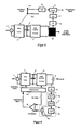
- FIG. 5 shown operating device and the operating method, with which this operating device works, set no unwanted modulation of the DC voltage according to FIG. 4 (b) of the high-frequency operating current according to FIG. 4 (c) more ahead.
- the PFC converter 2, the capacitor 3 and the half-bridge inverter 4 with resonance circuits not shown are designed and switched as in the known operating device according to FIG. 4 , In this respect, reference is made in full to these explanations.
- a detection signal is generated that under (e) is shown.
- This detection signal is low frequency and sawtooth.
- it is fed to the PFC converter 2 and, on the other hand, to an evaluation circuit which comprises a low-pass filter 6, two differentiating elements 7 and a comparator 9.
- the PFC converter 2 thus selectively generates a modulation of its output voltage, for example by modulation of the setpoint of its control, which modulation can be used as a detection signal.
- the modulation thus already affects the area of the generation of the DC supply voltage for the inverter.
- the modulation of the supply voltage is preferably sawtooth.
- the modulation of the output voltage of the PFC and thus the supply voltage of the inverter results in a high-frequency operating current generated by the operating device as shown under (f), which is thus modulated with the detection signal.
- the modulation signal of the operating current is filtered out with the low-pass filter 6 and then differentiated into a differentiator 7 after the time.
- the original generated detection signal is supplied to the differentiator 8 and also differentiated by time. If a sawtooth voltage is differentiated according to time, it is known that the result is a constant DC voltage. Such is therefore present at the output of the differentiating 8.
- the filtered out with the low-pass filter 6 modulation signal of the high-frequency operating current is also a pure sawtooth, so arises also at the output of the differentiating 7 a constant DC voltage.
- the output products of the two differentiating elements 7 and 8 are fed to a comparator 9. This generates at equality of the output products of the two differentiating 7 and 8 no signal. If, on the other hand, the modulation of the operating current according to (f) is distorted by an acoustic resonance, the result is no longer a constant direct voltage at the output of the differentiating element 7. As a result, the comparator 9 detects a difference between the voltages supplied thereto and accordingly generates a detection signal indicative of an acoustic resonance.
- the operating device after FIG. 6 is a bit more detailed than that FIG. 5 , It shows in particular a more concrete embodiment of the differentiating element 7.
- This consists of a sample-and-hold circuit 7a, an adjoining A / D converter 7b, a delay element 7c and a subtractor 7d.
- the filtered out of the low-pass filter 6 modulation signal of the high-frequency operating current is sampled in the sample-and-hold circuit 7a at certain intervals.
- the samples are digitized in the A / D converter 7b.
- the subtracter 7d is connected to the input and the output of the delay element 7c. The latter delays by the sampling time interval of the sample-and-hold circuit 7a.
- a signal value appears at the output of the subtractor 7d which is fed to the one input of the comparator 9.
- This signal value is a constant DC voltage, as long as the modulation signal filtered out of the high-frequency operating current is sawtooth-shaped.
- the other input of the comparator 9 is supplied with a reference value representing a differentiated original detection signal value. If the detection signal - as assumed in the present case - is sawtooth, then the reference value is also a constant DC voltage. The result of the comparison is reported by the comparator 9 of the control unit. As described, the comparator 9 outputs an acoustic resonance display of the detection signal only when the signal values supplied to the comparator 9 are unequal.
- the control unit is connected both to the PFC converter 2 and to the half-bridge inverter 4.
- the control unit 10 contains the generator (not shown) for generating the sawtooth-shaped detection signal and supplies this to the PFC converter 2. Further, the control unit 10 generates the high frequency at which the switches of the half-bridge inverter are clocked. When the controller 10 is reported by the comparator 9, a detection signal, the control unit 10 changes the high-frequency switching frequency for the half-bridge inverter 4 to counteract the acoustic resonance so that it disappears as possible again.
- control unit 10 is connected to the half-bridge inverter 4 to supply the detection signal to this.
- modulated the half-bridge inverter 4 the high frequency at which the switches of the half-bridge inverter are clocked.
- a full-bridge circuit can also be used instead of a half-bridge circuit.
Landscapes
- Circuit Arrangements For Discharge Lamps (AREA)
Claims (16)
- Procédé destiné à faire fonctionner une lampe HID (5), dans lequel :- un appareil d'actionnement présente un onduleur qui est alimenté par un convertisseur AC/DC à tension continue raccordé au réseau (1), l'onduleur produisant un courant de service à haute fréquence pour la lampe HID (5) avec lequel l'appareil d'actionnement alimente la lampe HID,- un filtre de fréquence (6) filtre un signal de détection périodique transmis à la lampe HID par l'appareil d'actionnement en même temps que le courant de service à haute fréquence, et- le signal de détection filtré par le filtre de fréquence (6) est amené à un montage d'exploitation, le montage d'exploitation analysant le signal de détection filtré pour constater une résonance acoustique,caractérisé- en ce qu'un générateur compris dans l'appareil d'actionnement module la tension d'alimentation de l'onduleur de l'appareil d'actionnement et produit ainsi le signal de détection de façon ciblée, c'est-à-dire indépendamment de la tension d'alimentation, pour l'objectif de la constatation de la résonance acoustique.
- Procédé selon la revendication 1,
dans lequel pour produire le signal de détection, la tension d'alimentation de l'onduleur est modulée de façon ciblée par un convertisseur PFC (2) cadencé activement de l'appareil d'actionnement, par exemple en ce que la valeur de consigne du réglage du convertisseur PFC est modulée. - Procédé selon l'une des revendications précédentes,
dans lequel le signal de détection a une durée de période et/ou une forme d'amplitude qui diffère de la durée de période et/ou de la forme d'amplitude de la modulation du courant de service de la lampe HID provoquée par une fréquence de réseau. - Procédé selon l'une des revendications précédentes,
caractérisé en ce que le signal de détection a une forme en dents de scie. - Procédé selon l'une des revendications précédentes,
caractérisé
en ce qu'à la fois le signal de détection produit par le générateur et le signal de détection filtré par le filtre de fréquence (6) sont différenciés en tant que tels en fonction du temps, puis comparés l'un avec l'autre. - Procédé selon la revendication 1,
caractérisé
en ce que le signal de détection filtré est obtenu à partir du courant de service modulé par filtrage dans un passe-bas,
en ce que le signal de détection filtré est balayé dans un circuit Sample-and-Hold, en ce que les valeurs de balayage sont ensuite numérisées dans un convertisseur A/D,
en ce que la valeur de balayage précédente retardée de l'intervalle de temps de balayage est soustraite de chaque valeur de balayage actuelle,
en ce que la valeur de soustraction est comparée avec une valeur de référence prédéfinie représentant une valeur effective de différenciation,
et en ce que si la valeur de soustraction diffère de la valeur de référence, un signal de constatation affichant une résonance acoustique est émis. - Procédé selon la revendication 6,
caractérisé
en ce que le signal de constatation est utilisé pour modifier la fréquence du courant de service à haute fréquence. - Appareil d'actionnement pour une lampe HID (5),
ayant un convertisseur AC/DC devant être raccordé au réseau (1),
ayant un onduleur alimenté en tension continue par le convertisseur AC/DC, qui produit un courant de service à haute fréquence pour la lampe HID (5),
ayant un filtre de fréquence (6) pour filtrer un signal de détection périodique transmis à la lampe HID par l'appareil d'actionnement en même temps que le courant de service à haute fréquence,
et ayant un montage d'exploitation auquel le signal de détection filtré est amené, le montage d'exploitation analysant le signal de détection filtré pour constater une résonance acoustique,
caractérisé
par un générateur compris dans l'appareil d'actionnement, qui module la tension d'alimentation de l'onduleur pour produire le signal de détection et produit ainsi le signal de détection de façon ciblée, c'est-à-dire indépendamment de la tension d'alimentation, pour l'objectif de la constatation de la résonance acoustique. - Appareil d'actionnement selon la revendication 8,
dans lequel pour produire le signal de détection, le générateur module la tension d'alimentation de l'onduleur de façon ciblée au moyen d'un convertisseur PFC (2) cadencé activement, par exemple en ce qu'une unité de commande module la valeur de consigne du réglage du convertisseur PFC (2). - Appareil d'actionnement selon la revendication 8 ou 9,
dans lequel le signal de détection a une durée de période et/ou une forme d'amplitude qui diffère de la modulation du courant de service de la lampe HID (5) provoquée par la tension du réseau. - Appareil d'actionnement selon l'une des revendications 8 à 10,
caractérisé
en ce que le convertisseur AC/DC présente un convertisseur PFC (2),
et en ce que l'onduleur est un inverseur à demi-pont (4) ayant deux commutateurs cadencés à haute fréquence en sens inverse. - Appareil d'actionnement selon l'une des revendications 8 à 11,
caractérisé
en ce que le montage d'exploitation contient deux parties de montage de différenciation (7, 8),
le signal de détection produit par le générateur étant amené à l'une (8) et le signal de détection filtré étant amené à l'autre (7),
et en ce que les sorties des deux parties de montage de différenciation (7, 8) sont reliées à un comparateur (9) qui, si le signal de détection filtré différencié diffère du signal de détection différencié, émet un signal de constatation affichant une résonance acoustique. - Appareil d'actionnement selon l'une des revendications 8 à 12,
caractérisé
en ce que la partie de montage de différenciation (7) pour le signal de détection filtré contient un circuit Sample-and-Hold (7a), un convertisseur A/D (7b) qui y est raccordé et un élément de retard (7c) qui y est raccordé,
en ce que le temps de retard de l'élément de retard (7c) est égal à l'intervalle de temps de balayage du circuit Sample-and-Hold (7a),
en ce que la partie de montage de différenciation (7) contient en outre un élément de soustraction (7d) qui est relié d'un côté à l'entrée et de l'autre côté à la sortie de l'élément de retard (7c),
en ce que la sortie de l'élément de soustraction (7d) est reliée à l'entrée d'un comparateur (9),
en ce qu'une valeur de référence, qui représente une valeur de signal de détection différenciée, est amenée à l'autre entrée du comparateur (9),
et en ce que le comparateur (9), si les valeurs de signal qui sont amenées à ses entrées diffèrent, émet un signal de constatation affichant une résonance acoustique. - Appareil d'actionnement selon l'une des revendications 12 ou 13,
caractérisé
en ce que l'appareil d'actionnement présente une unité de commande (10) qui contient le générateur destiné à produire le signal de détection,
en ce que l'unité de commande est reliée avec le comparateur (9) pour recevoir et pour analyser le signal de constatation,
en ce que l'unité de commande (10) est reliée avec le convertisseur AC/DC pour lui amener le signal de détection,
et en ce que l'unité de commande (10) est en outre reliée avec l'onduleur pour modifier la fréquence du courant de service à haute fréquence produit par celui-ci pour la lampe HID (5) lorsqu'un signal de constatation est amené à l'unité de commande (10). - Appareil d'actionnement selon l'une des revendications 12 à 14,
caractérisé
en ce que l'appareil d'actionnement présente une unité de commande (10) qui contient le générateur destiné à produire le signal de détection,
en ce que l'unité de commande est reliée avec le comparateur (9) pour recevoir et pour analyser le signal de constatation,
en ce que l'unité de commande (10) est reliée avec l'inverseur à demi-pont (4) pour lui amener le signal de détection,
et en ce que l'unité de commande (10) est en outre reliée avec l'inverseur à demi-pont (4) pour modifier la fréquence du courant de service à haute fréquence produit par celui-ci pour la lampe HID (5) lorsqu'un signal de constatation est amené à l'unité de commande (10). - Luminaire HID présentant un appareil d'actionnement selon l'une des revendications 8 à 15 ainsi qu'au moins une lampe HID raccordée.
Applications Claiming Priority (2)
| Application Number | Priority Date | Filing Date | Title |
|---|---|---|---|
| DE102008061088A DE102008061088A1 (de) | 2008-12-08 | 2008-12-08 | Verfahren und Betriebsgerät zum Feststellen einer akustischen Resonanz bei einer HID-Lampe |
| PCT/EP2009/066067 WO2010076105A1 (fr) | 2008-12-08 | 2009-11-30 | Procédé et ballast destinés à détecter une résonance acoustique d'une lampe hid (à décharge à haute intensité) |
Publications (2)
| Publication Number | Publication Date |
|---|---|
| EP2364577A1 EP2364577A1 (fr) | 2011-09-14 |
| EP2364577B1 true EP2364577B1 (fr) | 2015-08-12 |
Family
ID=41697955
Family Applications (1)
| Application Number | Title | Priority Date | Filing Date |
|---|---|---|---|
| EP09799054.3A Not-in-force EP2364577B1 (fr) | 2008-12-08 | 2009-11-30 | Procédé et ballast destinés à détecter une résonance acoustique d'une lampe hid (à décharge à haute intensité) |
Country Status (4)
| Country | Link |
|---|---|
| EP (1) | EP2364577B1 (fr) |
| CN (1) | CN102246601A (fr) |
| DE (1) | DE102008061088A1 (fr) |
| WO (1) | WO2010076105A1 (fr) |
Family Cites Families (6)
| Publication number | Priority date | Publication date | Assignee | Title |
|---|---|---|---|---|
| US5569984A (en) * | 1994-12-28 | 1996-10-29 | Philips Electronics North America Corporation | Method and controller for detecting arc instabilities in gas discharge lamps |
| US6005356A (en) * | 1996-10-21 | 1999-12-21 | Matsushita Electric Industrial Co., Ltd. | Operating method and operating apparatus for a high pressure discharge lamp |
| US5942860A (en) | 1997-09-16 | 1999-08-24 | Philips Electronics North America Corporation | Electronic ballast for a high intensity discharge lamp with automatic acoustic resonance avoidance |
| DE10045709A1 (de) * | 2000-09-15 | 2002-03-28 | Tridonic Bauelemente Gmbh Dorn | Elektronisches Vorschaltgerät |
| DE102004004828A1 (de) * | 2004-01-30 | 2005-08-18 | Patent-Treuhand-Gesellschaft für elektrische Glühlampen mbH | Betriebsverfahren für den Resonanzbetrieb von Hochdrucklampen im longitudinalen Mode und zugehöriges System und EVG |
| JP2007115660A (ja) * | 2005-09-22 | 2007-05-10 | Toshiba Lighting & Technology Corp | 高圧放電ランプ点灯装置及び照明装置 |
-
2008
- 2008-12-08 DE DE102008061088A patent/DE102008061088A1/de not_active Withdrawn
-
2009
- 2009-11-30 CN CN2009801493728A patent/CN102246601A/zh active Pending
- 2009-11-30 WO PCT/EP2009/066067 patent/WO2010076105A1/fr not_active Ceased
- 2009-11-30 EP EP09799054.3A patent/EP2364577B1/fr not_active Not-in-force
Also Published As
| Publication number | Publication date |
|---|---|
| CN102246601A (zh) | 2011-11-16 |
| DE102008061088A1 (de) | 2010-06-10 |
| WO2010076105A1 (fr) | 2010-07-08 |
| EP2364577A1 (fr) | 2011-09-14 |
Similar Documents
| Publication | Publication Date | Title |
|---|---|---|
| EP2457314B1 (fr) | Procédé et circuit pour l'amélioration de facteur de puissance | |
| DE69822619T2 (de) | Schaltung zur detektion von bogeninstabilitäten in entladungslampen starker intensität | |
| EP2188886B1 (fr) | Procédé de régulation d'un convertisseur à commutation | |
| EP2011217B1 (fr) | Circuit de correction du facteur de puissance d'un hacheur élévateur (boost-pfc) | |
| DE112006002495T5 (de) | Digitale Steuereinrichtung zur Leistungsfaktorkorrektur und diese aufweisende Wechselspannungs-zu-Gleichspannungsversorgung | |
| EP2292079B1 (fr) | Identification du type d'une ampoule au moyen d'un circuit de correction de facteur de puissance | |
| DE102007028785A1 (de) | Leistungsfaktor-Korrekturfilter, insbesondere für den Einsatz in einem elektronischen Vorschaltgerät für ein Leuchtmittel | |
| EP1872627B1 (fr) | Pfc numerique parametrable | |
| EP1227705A2 (fr) | Ballast pour lampes comprenant un convertisseur du type SEPIC | |
| DE19517950A1 (de) | Stromversorgungseinrichtung | |
| EP2368410B1 (fr) | Procédé et ballast pour le fonctionnement d'un moyen d'éclairage avec un courant régulé | |
| EP2364577B1 (fr) | Procédé et ballast destinés à détecter une résonance acoustique d'une lampe hid (à décharge à haute intensité) | |
| EP2132964A1 (fr) | Arrangement de circuit et procédé pour faire fonctionner une lampe à décharge à haute pression | |
| EP2130412B1 (fr) | Détection de défaut dans un appareil électrique pour moyen d'éclairage | |
| EP1189490B1 (fr) | Ballast électronique de lampe fluorescente | |
| EP1524576B1 (fr) | Convertisseur de tension survolteur avec régulation de facteur de puissance | |
| EP1189485B1 (fr) | Ballast électonique avec régulation de la tension intermédiaire | |
| EP1737279A2 (fr) | Dispositif et procédé d'élaboration d'une tension sinusoïdalement modulée en amplitude | |
| EP2094065B1 (fr) | Procédé destiné à la commande de flux lumineux de moyens d'éclairage réglables en intensité et agencement de commutation correspondant | |
| DE102005030599A1 (de) | Steuerungsverfahren für zweistufige Konverter | |
| WO2006042640A2 (fr) | Modulation d'une correction du facteur de puissance en cas de fonctionnement en courant continu | |
| EP2094066B1 (fr) | Procédé destiné à la commande de flux lumineux de moyens d'éclairage réglés et agencement de commutation correspondant | |
| DE102005004916A1 (de) | Verfahren zum Betreiben einer Hochdruckentladungslampe und Betriebsgerät für eine Hochdruckentladungslampe sowie Beleuchtungseinrichtung | |
| EP3552458B1 (fr) | Agencement de circuits et procédé de fonctionnement d'un moyen d'éclairage | |
| AT14723U1 (de) | Leistungsfaktorkorrektur mit Erfassung von Nulldurchgängen |
Legal Events
| Date | Code | Title | Description |
|---|---|---|---|
| PUAI | Public reference made under article 153(3) epc to a published international application that has entered the european phase |
Free format text: ORIGINAL CODE: 0009012 |
|
| 17P | Request for examination filed |
Effective date: 20110607 |
|
| AK | Designated contracting states |
Kind code of ref document: A1 Designated state(s): AT BE BG CH CY CZ DE DK EE ES FI FR GB GR HR HU IE IS IT LI LT LU LV MC MK MT NL NO PL PT RO SE SI SK SM TR |
|
| DAX | Request for extension of the european patent (deleted) | ||
| 17Q | First examination report despatched |
Effective date: 20131204 |
|
| GRAP | Despatch of communication of intention to grant a patent |
Free format text: ORIGINAL CODE: EPIDOSNIGR1 |
|
| INTG | Intention to grant announced |
Effective date: 20150504 |
|
| GRAS | Grant fee paid |
Free format text: ORIGINAL CODE: EPIDOSNIGR3 |
|
| GRAA | (expected) grant |
Free format text: ORIGINAL CODE: 0009210 |
|
| AK | Designated contracting states |
Kind code of ref document: B1 Designated state(s): AT BE BG CH CY CZ DE DK EE ES FI FR GB GR HR HU IE IS IT LI LT LU LV MC MK MT NL NO PL PT RO SE SI SK SM TR |
|
| REG | Reference to a national code |
Ref country code: GB Ref legal event code: FG4D Free format text: NOT ENGLISH |
|
| REG | Reference to a national code |
Ref country code: CH Ref legal event code: EP |
|
| REG | Reference to a national code |
Ref country code: AT Ref legal event code: REF Ref document number: 743105 Country of ref document: AT Kind code of ref document: T Effective date: 20150815 |
|
| REG | Reference to a national code |
Ref country code: IE Ref legal event code: FG4D Free format text: LANGUAGE OF EP DOCUMENT: GERMAN |
|
| REG | Reference to a national code |
Ref country code: DE Ref legal event code: R096 Ref document number: 502009011425 Country of ref document: DE |
|
| REG | Reference to a national code |
Ref country code: FR Ref legal event code: PLFP Year of fee payment: 7 |
|
| REG | Reference to a national code |
Ref country code: LT Ref legal event code: MG4D |
|
| REG | Reference to a national code |
Ref country code: NL Ref legal event code: MP Effective date: 20150812 |
|
| PG25 | Lapsed in a contracting state [announced via postgrant information from national office to epo] |
Ref country code: GR Free format text: LAPSE BECAUSE OF FAILURE TO SUBMIT A TRANSLATION OF THE DESCRIPTION OR TO PAY THE FEE WITHIN THE PRESCRIBED TIME-LIMIT Effective date: 20151113 Ref country code: LT Free format text: LAPSE BECAUSE OF FAILURE TO SUBMIT A TRANSLATION OF THE DESCRIPTION OR TO PAY THE FEE WITHIN THE PRESCRIBED TIME-LIMIT Effective date: 20150812 Ref country code: LV Free format text: LAPSE BECAUSE OF FAILURE TO SUBMIT A TRANSLATION OF THE DESCRIPTION OR TO PAY THE FEE WITHIN THE PRESCRIBED TIME-LIMIT Effective date: 20150812 Ref country code: FI Free format text: LAPSE BECAUSE OF FAILURE TO SUBMIT A TRANSLATION OF THE DESCRIPTION OR TO PAY THE FEE WITHIN THE PRESCRIBED TIME-LIMIT Effective date: 20150812 Ref country code: NO Free format text: LAPSE BECAUSE OF FAILURE TO SUBMIT A TRANSLATION OF THE DESCRIPTION OR TO PAY THE FEE WITHIN THE PRESCRIBED TIME-LIMIT Effective date: 20151112 |
|
| PGFP | Annual fee paid to national office [announced via postgrant information from national office to epo] |
Ref country code: GB Payment date: 20151130 Year of fee payment: 7 |
|
| PG25 | Lapsed in a contracting state [announced via postgrant information from national office to epo] |
Ref country code: PL Free format text: LAPSE BECAUSE OF FAILURE TO SUBMIT A TRANSLATION OF THE DESCRIPTION OR TO PAY THE FEE WITHIN THE PRESCRIBED TIME-LIMIT Effective date: 20150812 Ref country code: HR Free format text: LAPSE BECAUSE OF FAILURE TO SUBMIT A TRANSLATION OF THE DESCRIPTION OR TO PAY THE FEE WITHIN THE PRESCRIBED TIME-LIMIT Effective date: 20150812 Ref country code: PT Free format text: LAPSE BECAUSE OF FAILURE TO SUBMIT A TRANSLATION OF THE DESCRIPTION OR TO PAY THE FEE WITHIN THE PRESCRIBED TIME-LIMIT Effective date: 20151214 Ref country code: IS Free format text: LAPSE BECAUSE OF FAILURE TO SUBMIT A TRANSLATION OF THE DESCRIPTION OR TO PAY THE FEE WITHIN THE PRESCRIBED TIME-LIMIT Effective date: 20151212 Ref country code: SE Free format text: LAPSE BECAUSE OF FAILURE TO SUBMIT A TRANSLATION OF THE DESCRIPTION OR TO PAY THE FEE WITHIN THE PRESCRIBED TIME-LIMIT Effective date: 20150812 Ref country code: ES Free format text: LAPSE BECAUSE OF FAILURE TO SUBMIT A TRANSLATION OF THE DESCRIPTION OR TO PAY THE FEE WITHIN THE PRESCRIBED TIME-LIMIT Effective date: 20150812 |
|
| PGFP | Annual fee paid to national office [announced via postgrant information from national office to epo] |
Ref country code: AT Payment date: 20151125 Year of fee payment: 7 Ref country code: FR Payment date: 20151130 Year of fee payment: 7 |
|
| PG25 | Lapsed in a contracting state [announced via postgrant information from national office to epo] |
Ref country code: NL Free format text: LAPSE BECAUSE OF FAILURE TO SUBMIT A TRANSLATION OF THE DESCRIPTION OR TO PAY THE FEE WITHIN THE PRESCRIBED TIME-LIMIT Effective date: 20150812 |
|
| PG25 | Lapsed in a contracting state [announced via postgrant information from national office to epo] |
Ref country code: SK Free format text: LAPSE BECAUSE OF FAILURE TO SUBMIT A TRANSLATION OF THE DESCRIPTION OR TO PAY THE FEE WITHIN THE PRESCRIBED TIME-LIMIT Effective date: 20150812 Ref country code: DK Free format text: LAPSE BECAUSE OF FAILURE TO SUBMIT A TRANSLATION OF THE DESCRIPTION OR TO PAY THE FEE WITHIN THE PRESCRIBED TIME-LIMIT Effective date: 20150812 Ref country code: CZ Free format text: LAPSE BECAUSE OF FAILURE TO SUBMIT A TRANSLATION OF THE DESCRIPTION OR TO PAY THE FEE WITHIN THE PRESCRIBED TIME-LIMIT Effective date: 20150812 Ref country code: IT Free format text: LAPSE BECAUSE OF FAILURE TO SUBMIT A TRANSLATION OF THE DESCRIPTION OR TO PAY THE FEE WITHIN THE PRESCRIBED TIME-LIMIT Effective date: 20150812 Ref country code: EE Free format text: LAPSE BECAUSE OF FAILURE TO SUBMIT A TRANSLATION OF THE DESCRIPTION OR TO PAY THE FEE WITHIN THE PRESCRIBED TIME-LIMIT Effective date: 20150812 |
|
| PGFP | Annual fee paid to national office [announced via postgrant information from national office to epo] |
Ref country code: DE Payment date: 20160129 Year of fee payment: 7 |
|
| REG | Reference to a national code |
Ref country code: DE Ref legal event code: R097 Ref document number: 502009011425 Country of ref document: DE |
|
| PG25 | Lapsed in a contracting state [announced via postgrant information from national office to epo] |
Ref country code: RO Free format text: LAPSE BECAUSE OF FAILURE TO SUBMIT A TRANSLATION OF THE DESCRIPTION OR TO PAY THE FEE WITHIN THE PRESCRIBED TIME-LIMIT Effective date: 20150812 |
|
| PLBE | No opposition filed within time limit |
Free format text: ORIGINAL CODE: 0009261 |
|
| STAA | Information on the status of an ep patent application or granted ep patent |
Free format text: STATUS: NO OPPOSITION FILED WITHIN TIME LIMIT |
|
| PG25 | Lapsed in a contracting state [announced via postgrant information from national office to epo] |
Ref country code: MC Free format text: LAPSE BECAUSE OF FAILURE TO SUBMIT A TRANSLATION OF THE DESCRIPTION OR TO PAY THE FEE WITHIN THE PRESCRIBED TIME-LIMIT Effective date: 20150812 Ref country code: LU Free format text: LAPSE BECAUSE OF FAILURE TO SUBMIT A TRANSLATION OF THE DESCRIPTION OR TO PAY THE FEE WITHIN THE PRESCRIBED TIME-LIMIT Effective date: 20151130 |
|
| REG | Reference to a national code |
Ref country code: CH Ref legal event code: PL |
|
| 26N | No opposition filed |
Effective date: 20160513 |
|
| PG25 | Lapsed in a contracting state [announced via postgrant information from national office to epo] |
Ref country code: CH Free format text: LAPSE BECAUSE OF NON-PAYMENT OF DUE FEES Effective date: 20151130 Ref country code: LI Free format text: LAPSE BECAUSE OF NON-PAYMENT OF DUE FEES Effective date: 20151130 |
|
| REG | Reference to a national code |
Ref country code: IE Ref legal event code: MM4A |
|
| PG25 | Lapsed in a contracting state [announced via postgrant information from national office to epo] |
Ref country code: SI Free format text: LAPSE BECAUSE OF FAILURE TO SUBMIT A TRANSLATION OF THE DESCRIPTION OR TO PAY THE FEE WITHIN THE PRESCRIBED TIME-LIMIT Effective date: 20150812 |
|
| PG25 | Lapsed in a contracting state [announced via postgrant information from national office to epo] |
Ref country code: IE Free format text: LAPSE BECAUSE OF NON-PAYMENT OF DUE FEES Effective date: 20151130 |
|
| PG25 | Lapsed in a contracting state [announced via postgrant information from national office to epo] |
Ref country code: BG Free format text: LAPSE BECAUSE OF FAILURE TO SUBMIT A TRANSLATION OF THE DESCRIPTION OR TO PAY THE FEE WITHIN THE PRESCRIBED TIME-LIMIT Effective date: 20150812 Ref country code: HU Free format text: LAPSE BECAUSE OF FAILURE TO SUBMIT A TRANSLATION OF THE DESCRIPTION OR TO PAY THE FEE WITHIN THE PRESCRIBED TIME-LIMIT; INVALID AB INITIO Effective date: 20091130 Ref country code: SM Free format text: LAPSE BECAUSE OF FAILURE TO SUBMIT A TRANSLATION OF THE DESCRIPTION OR TO PAY THE FEE WITHIN THE PRESCRIBED TIME-LIMIT Effective date: 20150812 |
|
| REG | Reference to a national code |
Ref country code: DE Ref legal event code: R119 Ref document number: 502009011425 Country of ref document: DE |
|
| PG25 | Lapsed in a contracting state [announced via postgrant information from national office to epo] |
Ref country code: CY Free format text: LAPSE BECAUSE OF FAILURE TO SUBMIT A TRANSLATION OF THE DESCRIPTION OR TO PAY THE FEE WITHIN THE PRESCRIBED TIME-LIMIT Effective date: 20150812 |
|
| REG | Reference to a national code |
Ref country code: AT Ref legal event code: MM01 Ref document number: 743105 Country of ref document: AT Kind code of ref document: T Effective date: 20161130 |
|
| GBPC | Gb: european patent ceased through non-payment of renewal fee |
Effective date: 20161130 |
|
| PG25 | Lapsed in a contracting state [announced via postgrant information from national office to epo] |
Ref country code: BE Free format text: LAPSE BECAUSE OF NON-PAYMENT OF DUE FEES Effective date: 20151130 |
|
| REG | Reference to a national code |
Ref country code: FR Ref legal event code: ST Effective date: 20170731 |
|
| PG25 | Lapsed in a contracting state [announced via postgrant information from national office to epo] |
Ref country code: MT Free format text: LAPSE BECAUSE OF FAILURE TO SUBMIT A TRANSLATION OF THE DESCRIPTION OR TO PAY THE FEE WITHIN THE PRESCRIBED TIME-LIMIT Effective date: 20150812 Ref country code: TR Free format text: LAPSE BECAUSE OF FAILURE TO SUBMIT A TRANSLATION OF THE DESCRIPTION OR TO PAY THE FEE WITHIN THE PRESCRIBED TIME-LIMIT Effective date: 20150812 Ref country code: AT Free format text: LAPSE BECAUSE OF NON-PAYMENT OF DUE FEES Effective date: 20161130 |
|
| PG25 | Lapsed in a contracting state [announced via postgrant information from national office to epo] |
Ref country code: FR Free format text: LAPSE BECAUSE OF NON-PAYMENT OF DUE FEES Effective date: 20161130 |
|
| PG25 | Lapsed in a contracting state [announced via postgrant information from national office to epo] |
Ref country code: GB Free format text: LAPSE BECAUSE OF NON-PAYMENT OF DUE FEES Effective date: 20161130 Ref country code: DE Free format text: LAPSE BECAUSE OF NON-PAYMENT OF DUE FEES Effective date: 20170601 |
|
| PG25 | Lapsed in a contracting state [announced via postgrant information from national office to epo] |
Ref country code: MK Free format text: LAPSE BECAUSE OF FAILURE TO SUBMIT A TRANSLATION OF THE DESCRIPTION OR TO PAY THE FEE WITHIN THE PRESCRIBED TIME-LIMIT Effective date: 20150812 |