EP2364588A1 - Filtereinheit für Aquarien mit doppelter Geschwindigkeit - Google Patents
Filtereinheit für Aquarien mit doppelter Geschwindigkeit Download PDFInfo
- Publication number
- EP2364588A1 EP2364588A1 EP10425066A EP10425066A EP2364588A1 EP 2364588 A1 EP2364588 A1 EP 2364588A1 EP 10425066 A EP10425066 A EP 10425066A EP 10425066 A EP10425066 A EP 10425066A EP 2364588 A1 EP2364588 A1 EP 2364588A1
- Authority
- EP
- European Patent Office
- Prior art keywords
- cartridge
- filter
- filter unit
- filtering
- liquid flow
- Prior art date
- Legal status (The legal status is an assumption and is not a legal conclusion. Google has not performed a legal analysis and makes no representation as to the accuracy of the status listed.)
- Granted
Links
Images


Classifications
-
- A—HUMAN NECESSITIES
- A01—AGRICULTURE; FORESTRY; ANIMAL HUSBANDRY; HUNTING; TRAPPING; FISHING
- A01K—ANIMAL HUSBANDRY; AVICULTURE; APICULTURE; PISCICULTURE; FISHING; REARING OR BREEDING ANIMALS, NOT OTHERWISE PROVIDED FOR; NEW BREEDS OF ANIMALS
- A01K63/00—Receptacles for live fish, e.g. aquaria; Terraria
- A01K63/04—Arrangements for treating water specially adapted to receptacles for live fish
- A01K63/045—Filters for aquaria
Definitions
- the present invention relates, in its more general aspect, to a filter unit for aquariums.
- the invention is usefully applied as filter unit for domestic aquarium, more particularly of the type designed to be hung according to a so-called "hang on back" configuration on one of the walls of the tank of said aquarium.
- the proper outfitting of an aquarium normally includes the installation of a filter unit, which is required to perform an action of recirculation and purification of the water, essential for the physiological well-being of the fish fauna contained in the tank.
- a device of this kind provides in general for a forced fluid path which traverses one or more filter bodies, positioned inside compartments which are arranged in series inside a container.
- the unit normally comprises pumping means, constituted for example by a synchronous electric pump, designed to aspirate water from the tank of the aquarium, convey it via the fluid path and return it, purified, into the same tank.
- At least one of the filter bodies is always arranged to perform filtering of a purely mechanical type, while others, assigned to filtering processes of a biological and/or chemical type, can be present in the more sophisticated filters.
- the body arranged for mechanical filtering of the water generally synthetic sponge or wool, intercepts the coarser impurities present in the liquid flow which traverses the filter unit.
- the filter body intended for biological filtering is instead formed, in some of the filter units according to the prior art, by a bed of tubes, i.e. small cylinders in a ceramic material designed to be colonised by bacteria, which in turn perform the actual purification of the water, transforming the waste substances generated by the organisms present in the aquarium into innocuous compounds.
- the filter body intended instead for chemical filtering is normally activated carbon. Its function is that of absorbing some noxious elements, eliminating them from the filtered water.
- both biological filtering and adsorbent filtering processes produce better results when the flow of the water through the relative filters is sufficiently slow.
- the bacteria succeed in settling better and the time the water stays in contact with the active materials increases.
- the technical problem at the base of the present invention is, therefore, that of devising a filter unit able to reconcile the opposing needs expressed above, i.e. allowing an optimal action of the biological and/or chemical filters contained therein while maintaining a discretionally reduced time of recirculation of the water.
- a filter unit for aquariums comprising: a container, provided with a fluid inlet and a fluid outlet to allow fluid communication thereof with an aquarium tank; pumping means intended for the circulation of a liquid flow inside said container between said fluid inlet and said fluid outlet along at least one main path; a first filter, arranged to intercept the whole of the liquid flow which follows said main path, performing thereon at least one mechanical filtering action; at least one second filter, arranged to perform at least one filtering action other than the mechanical one (i.e.
- the main path is divided into at least one first slow subpath and a fast subpath, said second filter being arranged to intercept, slowing it down, only the part of the liquid flow which follows the first slow subpath, while the part of liquid flow which follows the fast subpath bypasses said second filter without being slowed down by it.
- the division of the fluid path into two or more subpaths allows on the one hand the guarantee of the time necessary for an effective filtering action of the chemical-biological type inside the second filter, and on the other hand the maintaining of a high speed of recirculation of the water which traverses only the first mechanical filter.
- the second filter may advantageously comprise a second cartridge, traversed by the first slow subpath and arranged to contain filtering material, preferably a material with chemical and/or biological action.
- the cartridge has to provide at least one access aperture and at least one exit aperture.
- the second cartridge can be inserted extractably inside a second compartment of the container.
- the liquid flow which follows the fast subpath can circulate inside the volume of the second compartment not occupied by said second cartridge.
- the fast subpath can follow a lower passage defined above by the second cartridge and below by a base wall which defines the second compartment below.
- the access apertures of the second cartridge can be a plurality and can open on one side of the same cartridge, while the exit apertures can also be a plurality and can open on an opposite side of the cartridge.
- the number and the arrangement of the apertures mentioned above have the advantage of guaranteeing an effective transit of the liquid flow through the cartridge.
- the liquid flow in order to follow the alternative fast subpath which extends below the cartridge, must lap the apertures positioned on the sides of the same. A portion of liquid flow then penetrates the cartridge to exit on the opposite side, bypassing the lower passage of the fast subpath.
- the overall area of the access apertures can be chosen to be greater than the overall area of the exit apertures.
- the filter unit can also comprise a third filter, also arranged to perform at least one filtering action other than the mechanical one.
- the presence of the third filter advantageously allows the second and the third filter to be assigned one to chemical filtering and the other to biological filtering of the liquid.
- the third filter can comprise a third cartridge, equipped with at least one access aperture and at least one exit aperture, arranged to contain filtering material, which can be inserted extractably inside the second compartment superimposed on the second cartridge.
- the first filter can comprise a first cartridge inserted extractably inside a filtering chamber of the container and at least one filtering medium supported by said first cartridge.
- This feature has the advantage of allowing easy maintenance of the filtering medium which constitutes the mechanical filter, facilitating its periodical replacement and/or cleaning.
- the filtering medium can be formed by a filtering sponge or by two juxtaposed filtering sponges.
- the sponge positioned upstream can be arranged to intercept the coarser impurities, while the one farther downstream can be arranged to stop the finer residues.
- the first cartridge can comprise below a cup intended to house the lower end of the filtering medium mentioned above.
- the presence of the cup prevents the accumulation on the base of the filtering chamber of those impurities which, intercepted by the filtering medium, deposit on the base thereof.
- the first cartridge can define above an overflow chamber configured to fill up in the case of clogging of the first filter, said overflow chamber having an outflow hole for letting the excess liquid flow out into a first compartment of the filtering chamber upstream of said filtering medium.
- the filter unit can also comprise an overflow indicator comprising in turn a float housed in the overflow chamber and integral with an indicator rod slidingly housed inside a hole open towards the outside of the container.
- the filter unit can comprise a further fluid path in addition to that which traverses the abovementioned filters. More particularly, a secondary path can be defined for the liquid flow which traverses a fourth fluid comprising a percolator.
- Said path can traverse from above downwards a third sponge positioned above said percolator.
- This sponge can comprise two fabrics having a different pattern which enclose one with the other a sponge body.
- the upstream fabric can have holes of a certain size while the downstream fabric has holes of smaller dimension.
- This structural peculiarity allows the sponge to filter particulate of different grain size mechanically: the upstream fabric retains the coarse detritus, the downstream fabric the fine type. As a result the sponge works by performing mechanical filtering along its whole thickness.
- This sponge also acts as biological material in that the body of the sponge retains in an optimal manner the beneficial bacteria.
- Said sponge of innovative type can also be used in filter units different from the one according to the present invention; it can also be used in the first filter of the present filter unit.
- the secondary path with percolator guarantees better oxygenation of the filtered liquid, improving the filtering efficacy of the filter unit.
- the percolator can be more particularly formed by a percolator cover which closes the third cartridge above, which in this case can be filled with biological filtering material.
- the filter unit can comprise an intake tube in fluid communication with the fluid inlet, it being possible to manipulate said intake tube so as to vary its alignment with an intake of a volute of the pumping means.
- This technique allows the regulation in a simple manner of the flow rate of the filter unit, without having to regulate the speed of the same pumping means.
- the regulation of the flow rate can be used both to prime said pumping means on starting, and to adapt to particular needs of the fauna and of the flora contained in the aquarium tank.
- the container of the filter unit can be arranged to be associated astride a wall of an aquarium tank.
- the fluid outlet will in this case take the shape of an overfall spillway arranged to face towards the interior of the same aquarium tank.
- 1 denotes generically a filter unit for aquariums.
- the preferred embodiment described with reference to said drawings relates to a filter unit for domestic aquariums of the so-called "hang on back” type, i.e. arranged to be hung astride over one of the lateral walls of an aquarium tank (not illustrated).
- the filter unit 1 is shown in the drawings according to a normal working configuration; further on in the present description the positions and the orientations, relative and absolute, of the various elements which make up the unit, defined by means of terms such as upper and lower, above and below, horizontal and vertical or other equivalent terms, should always be interpreted with reference to this configuration.
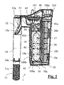
- the filter unit 1 comprises a container 10, inside whereof the operations are performed of filtering of a liquid flow drawn from the aquarium tank and returned there once filtering has taken place.
- the container 10 has externally the shape of a parallelepiped whose lower portions exhibits a lateral recess to make room for pumping means 20 described herein below.
- the external walls which define the container 10 are a base wall 10a wherefrom a front wall 10b, a rear wall 10c, a first continuous side wall 10d and a second side wall 10e rise up.
- the latter is made up of two separate vertical portions joined one to the other by a horizontal portion 10g, to form the previously mentioned recess.
- the lower vertical portion of the second side wall 10e continues inside the container 10 with a dividing septum 10f which divides the same container 10 into two adjacent chambers: a volute chamber 80 and a filtering chamber 81.
- the container 10 is provided with an attachment appendage 15 which allows it to be hung astride the side wall of the aquarium tank.
- This attachment appendage 15 extends longitudinally along the entire upper edge of the front wall 10b.
- an external portion of an intake tube 14 extends vertically downwards.
- Said external portion of the intake tube 14 comprises an upper support part below which an extension 14a engages, through form coupling.
- the extension 14a is arranged to be immersed in the water of the aquarium tank.
- the immersed part has a plurality of horizontal slots 11a which define a fluid inlet 11 of the filter unit 1.
- an overfall spillway 12a opens which defines a fluid outlet 12 of the filter unit 1.
- the upper surface of the attachment appendage 15 defines, below said overfall spillway 12a, a re-entry chute 15a intended to accompany the fall of the now filtered water inside the aquarium tank.
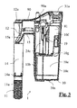
- a main path 100 and a secondary path 101 are defined inside the container 10: a main path 100 and a secondary path 101.
- the main path also divides into three different subpaths: a fast subpath 100a, a first slow subpath 100b and a second slow subpath 100c.
- the pumping means 20 are intended to promote the circulation of the liquid flow along the abovementioned path and subpaths.
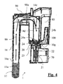
- said pumping means 20 take the shape of a synchronous electric pump which comprises a synchronous electric motor 21, contained inside a box-like body 70 positioned below the horizontal portion 10g of the second side wall 10e to occupy the space defined by the recess in said wall.
- the synchronous electric pump comprises also a rotor 22 which turns inside a volute 24 contained on the base of the volute chamber 80 of the container 10.
- the volute chamber 80 is connected below to the box-like body 70 by means of a connection sleeve 23, which allows a removable engaging of the box-like body 70 on the base of the container 10.
- Inside the connection hose 23 runs the transmission shaft which connects the rotor 22 to the synchronous electric motor 21.
- All the abovementioned paths share a common section 99, which extends from the fluid inlet 11 previously defined as far as an intake 24a of the volute 21.
- Said common section 99 is defined internally by the extension 14a and by the intake tube 14.
- the intake tube 14 provides an elbow portion 14c which connects the external portion thereof described previously to a descending portion 14d which flows out at the intake 24a of the volute 24, positioned on the base of the volute chamber 80.
- the intake tube 14 is rotatingly mobile so as to be able to move its mouth from the position of alignment with the intake 24a of the volute 24, adjusting in this way the flow rate of the liquid flow which circulates between fluid inlet 11 and outlet 12.
- the intake 24a of the volute 24 opens axially in relation to the rotor 22; the volute 24 comprises a main delivery channel 24b and a secondary delivery channel 24c (which can be seen in Figure 3 ) which depart radially in relation to the rotor 22.
- the main path 100 follows the main delivery channel 24b, while the secondary path 101 follows the secondary delivery channel 24c.
- both the delivery channels 24b and 24c comprise a rising section which follows the radial section, to then open at a higher level in relation to that of the intake 24a; thanks to this technique, complete emptying of the volute 24 is avoided in the case of stopping of the pumping means 20, allowing restarting of the latter without difficulties linked to priming.
- the main delivery channel 24a branches off radially towards the rear wall 10c of the container 10, then moves upwards, flanking said wall and leading into the filtering chamber 81 through a hole which opens at mid height of the dividing septum 10f.
- a first cartridge 31, a second cartridge 41 and a third cartridge 51 are inserted which constitute respectively, together with their contents described herein below, a first filter 30, a second filter 40 and a third filter 50.
- the main path 100 and its subpaths 100a, 100b, 100c run between said cartridges and in their interior.
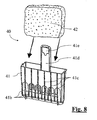
- the first cartridge 31, shown in the accompanying Figures 5-7 is arranged to be housed in the rear part of the filtering chamber 81. It comprises a main body, which extends planarly inside the filtering chamber 81, topped by a rear closure cover 31 a, which instead remains outside of the filtering chamber 81, closing it above. Said rear closure cover 31a expands laterally, projecting in relation to the main body, so as to cover also a rear part of the volute chamber 80.
- the cover 31 a is associated with hooks for engaging with the main body of the first cartridge 31 and is provided with two grooves 31j intended to facilitate gripping thereof from the outside. By acting on the cover 31a by means of the grooves 31j it is therefore possible to raise the entire first cartridge 31, extracting it vertically from the container 10.
- the main body of the first cartridge 31 comprises a support cage intended to maintain in position a first and a second juxtaposed filtering sponge 32, 33.
- the filtering sponges 32, 33 are arranged to perform filtering of a mainly mechanical type on the liquid flow which traverses them; more particularly, the first filtering sponge 32, positioned towards the rear wall 10c of the container 10, is arranged to perform a coarser mechanical filtering, the second filtering sponge 33 is instead intended for a finer mechanical filtering.
- the support cage comprises a cup 31b intended to house the lower end of the two filtering sponges 32, 33. Inside said cup 31b impurities and dirt retained by the sponges are deposited; the presence of the cup prevents their accumulation on the base of the container 10, which is less easy to clean.
- the cup 31b is provided below with a plurality of drain apertures.
- the support cage Abutting against the rear wall 10c of the container 10, the support cage therefore defines a first compartment 81a of the filtering chamber 81; a second compartment 81b is instead formed by the portion of filtering chamber beyond the front grate 3 1 c.
- the liquid flow enters the first compartment 81a upstream of the filtering sponges 32, 33; continuing along the main path 100, said liquid flow must then traverse horizontally said filtering sponges 32, 33 to flow, through the front grate 31c, into the second compartment 81 b.
- the first filter 30, which comprises the first cartridge 31 and the filtering sponges 32, 33 contained therein, is arranged to intercept all the liquid flow which follows the main path 100.
- the abovementioned support cage is closed by a horizontal septum 31i which delimits below an overflow chamber 31f, which has an outflow hole 31h communicating with the volute chamber 80.
- the outflow hole 31h is formed at a slightly higher level compared to that of the horizontal septum 31i.
- the liquid flow gradually fills the first compartment 81a, until seeping, via the slots which separate the horizontal septum 31i from the rear wall 10c of the container 10, inside the overflow chamber 31f.
- the liquid rises in level until it reaches the level of the outflow hole 31h, through which it can return into the volute chamber 80.
- the filter unit 1 comprises an overflow indicator 31g, formed by a rectangular float from which an indicator rod leads off.
- the float is contained in the overflow chamber 31f, while the indicator rod is slidingly inserted in a hole which traverses the upper wall of the chamber and the cover 31 a of the first cartridge 31.
- the float When the overflow chamber 31f is empty, the float rests on the horizontal septum 31i. The indicator rod is then completely housed inside the hole which traverses the cover 31a. When the chamber fills with liquid due to a clogging of the filtering sponges 32, 33, the float rises and draws with it the indicator rod, which therefore emerges from the external surface of the cover, indicating visually the condition of malfunctioning of the filter unit 1.
- the second cartridge 41 and, above it, the third cartridge 51 are inserted vertically.
- Both the second 41 and third cartridge 51 are arranged to contain filtering material and are provided with rear inlet apertures 41a, 51a (i.e. turned towards the front grate 31c) and front outlet apertures 41b, 51b (i.e. turned towards the front wall 10b) for the liquid flow.
- the second cartridge 41 and the filtering material contained therein constitute the second filter 40; the third cartridge 51 and the filtering material contained therein constitute the third filter 50.
- the second cartridge 41 and the third cartridge 51 are slightly displaced both from the front grate 31c and from the front wall 10b. Moreover the second cartridge 41 does not extend as far as the base wall 10a of the container 10. Said cartridges are instead in contact with the first side wall 10d on one side and with the dividing septum 10f on the other.
- the rear interspace 17 and the front one 18 are in fluid communication both via the opposite apertures of the interposed cartridges and via a lower passage 16 formed between the second cartridge 41 and the base wall 10a of the container 10, i.e. defined by the lower portion of second compartment 81 b not occupied by the second cartridge 41.
- the slow subpaths are thus named because, when the second 41 and the third cartridge 51 are filled with filtering material, the latter slows down the circulation of the liquid flow through the same cartridges.
- the dividing septum 10f has a recirculation aperture 19 which places in communication the second compartment 81b of the filtering chamber 81 with the volute chamber 80. More particularly, said recirculation aperture 19 opens onto the rear interspace 17.
- the recirculation aperture 19 allows a partial recirculation of the liquid flow should the flow rate of the filter unit 1, which can be regulated by manipulation of the intake tube 14, not be maximum.
- the second cartridge 41 contains an adsorbent filtering material 42: carbon or another suitable material which offers an extensive surface area for the adsorption of the impurities of the liquid flow.
- the third cartridge 51 contains instead a biological filtering material 52: ceramic tubes or another suitable material for hosting bacterial colonies with purification capacities.
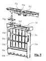
- the second cartridge 41 is shaped like a basket, open above.
- the entrance apertures 41a rectangular in shape, open on two superimposed rows. Eight entrance apertures 41a are present on each row.
- the exit apertures 41b ten in number, are instead formed on a single row on the opposite side of the basket. It should be noted that the number of apertures may vary according to the dimensions of the filter unit; more particularly for smaller filter units compared to the one according to the present embodiment the apertures will be in a smaller number (for example two rows with six entrance apertures and one row of eight for the exit apertures). They extend as far as the base of the basket and also have a substantially rectangular shape, with rounded upper end.
- Each exit aperture 41 b is divided in half by a reinforcement ribbing 41c which runs vertically along the entire extension of the basket.
- the total area of the exit apertures 41b is smaller than the total area of the entrance apertures 41a to ensure the water stays for a long length of time inside the cartridge.
- a sleeve 41 d which also acts as a hooking member between the second 41 and the third cartridge 51. It has in fact at its end a hooking hole 41e arranged to house a tooth 51e of the third cartridge 51.
- the third cartridge 51 is also shaped like a basket open above. Said third cartridge 51 is superimposed over the second 41, closing it above with its base.
- the front one has a balcony portion 51d projecting in relation to the base of the cartridge.
- Said balcony portion 51d extends inside a space defined internally by the attachment appendage 15 of the filter unit.
- the third cartridge 51 has secondary apertures 51c positioned on the front side of the basket yet below the balcony portion 51d.
- Said secondary apertures 51d which have a total area greater both than the entrance apertures 51a and the exit apertures 51b of the third cartridge 51, have as primary function that of promoting complete flooding of the biological filtering material 52 contained in cartridge 51.
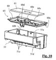
- the third cartridge 51 is closed above by a percolator cover 60.
- Said percolator cover 60 is locked on the third cartridge by means of rear feet 60a and of a front snap joint 60b, which co-operate with respective seats of the third cartridge 51.
- an operator In order to lock the percolator cover 60 on the third cartridge 51, an operator must first insert the rear feet 60a in their respective seats then, by hinging on said rear feet 60a, rotate the percolator cover until the snap joint 60b is locked in its seat. Contrarily, the removal of the percolator cover 60 first provides for the disengaging of the snap joint 60b and then the extraction of the rear feet 60a.
- the percolator cover 60 has a central depression 60c intended to hold a third filtering sponge 61 mainly intended for the mechanical filtering of the liquid flow.
- Said third filtering sponge 61 which can be seen in the photos which make up Figures 13-15 , comprises two fabrics, an upstream fabric 61a and a downstream fabric 61b, which enclose between them a sponge body 61c.
- the upstream fabric 61a and the downstream fabric 61b have a different pattern; the sponge body 61c placed between them is formed by threads orthogonal to said fabrics.
- the downstream fabric 61 b has instead rectangular holes 61f of smaller size (approximately 0.52 x 0.60 mm for a surface of 0.31 mm 2 ). These holes are also arranged in rows distanced by short close weave bands 61g.
- the third sponge 61 which has a thickness of approximately 3 mm, is inserted on the percolator 60 in such a way that the downstream fabric is turned towards the base of the central depression 60c.
- the third sponge 61 works by performing mechanical filtering along the whole of its thickness: in fact the upstream fabric 61a retains the coarse detritus, the downstream fabric 61b the fine type.
- the percolator cover 60 is traversed by a plurality of appropriately calibrated percolation holes 60d which open on the base of the aforesaid central depression 60c.
- the percolator cover 60 is equipped with a handle 60e and projecting in relation to the central depression 60c.
- Said handle 60e traverses the third filtering sponge 61 and can be gripped by an operator who, by virtue of the rigid coupling formed by the rear feet 60a and by the snap joint 60b described previously, is able to extract, by acting on it, the entire third cartridge 51-percolator cover 60 block.
- the secondary path 101 previously introduced traverses a fourth filter 65 defined by said percolator cover 60 and by the third filtering sponge 61 positioned above it.
- the secondary path 101 follows in fact the secondary delivery channel 24c of the volute 24, which positions at the dividing septum 11c and rises up along the latter to then flow out above the percolator cover 60.
- the liquid flow which follows the secondary path 101 then traverses the third filtering sponge 61 to then percolate through the percolation holes 60d inside of the third cartridge 51. Finally the liquid flow flows out from the exit apertures 51b of the cartridge and from the overfall spillway 12a, then returning into the aquarium tank.
- the liquid flow which follows the secondary path 101 enriches with the oxygen necessary for a correct oxidation of the ammonia contained therein.
- the filter unit 1 also provides a front closure cover 90 which covers the portion of container 10 left free by the rear closure cover 31a.
- Said front closure cover 90 has an upper shaped surface 90a, acting as a drainer to return to the aquarium tank the water which may possibly flow out from the container 10.
Landscapes
- Life Sciences & Earth Sciences (AREA)
- Environmental Sciences (AREA)
- Marine Sciences & Fisheries (AREA)
- Animal Husbandry (AREA)
- Biodiversity & Conservation Biology (AREA)
- Farming Of Fish And Shellfish (AREA)
- Water Treatment By Sorption (AREA)
Priority Applications (1)
| Application Number | Priority Date | Filing Date | Title |
|---|---|---|---|
| EP20100425066 EP2364588B1 (de) | 2010-03-12 | 2010-03-12 | Filtereinheit für Aquarien mit doppelter Geschwindigkeit |
Applications Claiming Priority (1)
| Application Number | Priority Date | Filing Date | Title |
|---|---|---|---|
| EP20100425066 EP2364588B1 (de) | 2010-03-12 | 2010-03-12 | Filtereinheit für Aquarien mit doppelter Geschwindigkeit |
Publications (2)
| Publication Number | Publication Date |
|---|---|
| EP2364588A1 true EP2364588A1 (de) | 2011-09-14 |
| EP2364588B1 EP2364588B1 (de) | 2012-11-28 |
Family
ID=42543021
Family Applications (1)
| Application Number | Title | Priority Date | Filing Date |
|---|---|---|---|
| EP20100425066 Active EP2364588B1 (de) | 2010-03-12 | 2010-03-12 | Filtereinheit für Aquarien mit doppelter Geschwindigkeit |
Country Status (1)
| Country | Link |
|---|---|
| EP (1) | EP2364588B1 (de) |
Cited By (2)
| Publication number | Priority date | Publication date | Assignee | Title |
|---|---|---|---|---|
| WO2014196857A1 (en) * | 2013-06-04 | 2014-12-11 | Van Amerongen Jasper Michaël | Aquarium filter |
| CN113473848A (zh) * | 2019-03-04 | 2021-10-01 | 斯派克初姆布兰斯有限公司 | 包括前置过滤构件的水族缸过滤器装置和方法 |
Citations (3)
| Publication number | Priority date | Publication date | Assignee | Title |
|---|---|---|---|---|
| US4915828A (en) * | 1989-04-12 | 1990-04-10 | Raymond Meyers | Aquarium filter |
| US5084164A (en) * | 1990-05-31 | 1992-01-28 | Luis Del Rosario | Filter assembly for an aquarium |
| EP0484896A1 (de) * | 1990-11-09 | 1992-05-13 | ASKOLL S.p.A. | Aquarienfilter |
-
2010
- 2010-03-12 EP EP20100425066 patent/EP2364588B1/de active Active
Patent Citations (3)
| Publication number | Priority date | Publication date | Assignee | Title |
|---|---|---|---|---|
| US4915828A (en) * | 1989-04-12 | 1990-04-10 | Raymond Meyers | Aquarium filter |
| US5084164A (en) * | 1990-05-31 | 1992-01-28 | Luis Del Rosario | Filter assembly for an aquarium |
| EP0484896A1 (de) * | 1990-11-09 | 1992-05-13 | ASKOLL S.p.A. | Aquarienfilter |
Cited By (4)
| Publication number | Priority date | Publication date | Assignee | Title |
|---|---|---|---|---|
| WO2014196857A1 (en) * | 2013-06-04 | 2014-12-11 | Van Amerongen Jasper Michaël | Aquarium filter |
| US9814220B2 (en) | 2013-06-04 | 2017-11-14 | Jasper Michael VAN AMERONGEN | Aquarium filter |
| CN113473848A (zh) * | 2019-03-04 | 2021-10-01 | 斯派克初姆布兰斯有限公司 | 包括前置过滤构件的水族缸过滤器装置和方法 |
| CN113473848B (zh) * | 2019-03-04 | 2024-01-02 | 斯派克初姆布兰斯有限公司 | 包括前置过滤构件的水族缸过滤器装置和方法 |
Also Published As
| Publication number | Publication date |
|---|---|
| EP2364588B1 (de) | 2012-11-28 |
Similar Documents
| Publication | Publication Date | Title |
|---|---|---|
| US5171438A (en) | Aquarium filtration system | |
| US9079784B2 (en) | Water filter system | |
| AU2017267212B2 (en) | Filter apparatus and method | |
| US6659043B1 (en) | Aquarium water circulation system | |
| US2981228A (en) | Display tank for shellfish | |
| US3525435A (en) | Disposable filter cartridge for aquariums | |
| KR100513904B1 (ko) | 외부식 여과장치 | |
| EP2364588B1 (de) | Filtereinheit für Aquarien mit doppelter Geschwindigkeit | |
| KR20100076721A (ko) | 수족관용 정수장치 및 이를 이용한 수족관 | |
| WO2008074252A1 (fr) | Vivier | |
| EP3784033B1 (de) | Wasserfilter für ein aquarium | |
| CN112889741A (zh) | 水生生物养殖系统 | |
| KR102314518B1 (ko) | 질산염 제거 시스템 및 이에 포함되는 탈질 여과조 | |
| EP2281452B1 (de) | Filtereinheit für einen Aquariumbehälter, die mindestens eine herausnehmbare Filterpatrone enthält | |
| US10524456B2 (en) | Filtering device for aquariums and the like | |
| RU110927U1 (ru) | Установка для выращивания молоди рыб | |
| JP2000106785A (ja) | 水棲生物育成装置 | |
| KR102387473B1 (ko) | 수조의 정수장치 | |
| CN208402850U (zh) | 一种畜牧养殖用饮水装置 | |
| KR101957560B1 (ko) | 사이클론 원심분리방식 필터를 적용한 외부 여과기 | |
| CN223060829U (zh) | 净水机 | |
| CN218389284U (zh) | 饮水机水路和宠物饮水机 | |
| KR101423385B1 (ko) | 정수기 | |
| KR102349615B1 (ko) | 순환형 스키머 및 하단 여과 일체형 수조 | |
| JP3768054B2 (ja) | 浄化槽の仕切壁構造 |
Legal Events
| Date | Code | Title | Description |
|---|---|---|---|
| PUAI | Public reference made under article 153(3) epc to a published international application that has entered the european phase |
Free format text: ORIGINAL CODE: 0009012 |
|
| AK | Designated contracting states |
Kind code of ref document: A1 Designated state(s): AT BE BG CH CY CZ DE DK EE ES FI FR GB GR HR HU IE IS IT LI LT LU LV MC MK MT NL NO PL PT RO SE SI SK SM TR |
|
| AX | Request for extension of the european patent |
Extension state: AL BA ME RS |
|
| RIN1 | Information on inventor provided before grant (corrected) |
Inventor name: MARIONI, ELIO |
|
| 17P | Request for examination filed |
Effective date: 20120314 |
|
| GRAP | Despatch of communication of intention to grant a patent |
Free format text: ORIGINAL CODE: EPIDOSNIGR1 |
|
| GRAS | Grant fee paid |
Free format text: ORIGINAL CODE: EPIDOSNIGR3 |
|
| GRAA | (expected) grant |
Free format text: ORIGINAL CODE: 0009210 |
|
| AK | Designated contracting states |
Kind code of ref document: B1 Designated state(s): AT BE BG CH CY CZ DE DK EE ES FI FR GB GR HR HU IE IS IT LI LT LU LV MC MK MT NL NO PL PT RO SE SI SK SM TR |
|
| REG | Reference to a national code |
Ref country code: GB Ref legal event code: FG4D |
|
| REG | Reference to a national code |
Ref country code: CH Ref legal event code: EP |
|
| REG | Reference to a national code |
Ref country code: AT Ref legal event code: REF Ref document number: 585654 Country of ref document: AT Kind code of ref document: T Effective date: 20121215 |
|
| REG | Reference to a national code |
Ref country code: IE Ref legal event code: FG4D |
|
| REG | Reference to a national code |
Ref country code: DE Ref legal event code: R096 Ref document number: 602010003842 Country of ref document: DE Effective date: 20130124 |
|
| REG | Reference to a national code |
Ref country code: AT Ref legal event code: MK05 Ref document number: 585654 Country of ref document: AT Kind code of ref document: T Effective date: 20121128 |
|
| REG | Reference to a national code |
Ref country code: NL Ref legal event code: VDEP Effective date: 20121128 |
|
| REG | Reference to a national code |
Ref country code: LT Ref legal event code: MG4D |
|
| PG25 | Lapsed in a contracting state [announced via postgrant information from national office to epo] |
Ref country code: SE Free format text: LAPSE BECAUSE OF FAILURE TO SUBMIT A TRANSLATION OF THE DESCRIPTION OR TO PAY THE FEE WITHIN THE PRESCRIBED TIME-LIMIT Effective date: 20121128 Ref country code: LT Free format text: LAPSE BECAUSE OF FAILURE TO SUBMIT A TRANSLATION OF THE DESCRIPTION OR TO PAY THE FEE WITHIN THE PRESCRIBED TIME-LIMIT Effective date: 20121128 Ref country code: NO Free format text: LAPSE BECAUSE OF FAILURE TO SUBMIT A TRANSLATION OF THE DESCRIPTION OR TO PAY THE FEE WITHIN THE PRESCRIBED TIME-LIMIT Effective date: 20130228 Ref country code: ES Free format text: LAPSE BECAUSE OF FAILURE TO SUBMIT A TRANSLATION OF THE DESCRIPTION OR TO PAY THE FEE WITHIN THE PRESCRIBED TIME-LIMIT Effective date: 20130311 Ref country code: FI Free format text: LAPSE BECAUSE OF FAILURE TO SUBMIT A TRANSLATION OF THE DESCRIPTION OR TO PAY THE FEE WITHIN THE PRESCRIBED TIME-LIMIT Effective date: 20121128 |
|
| PG25 | Lapsed in a contracting state [announced via postgrant information from national office to epo] |
Ref country code: BE Free format text: LAPSE BECAUSE OF FAILURE TO SUBMIT A TRANSLATION OF THE DESCRIPTION OR TO PAY THE FEE WITHIN THE PRESCRIBED TIME-LIMIT Effective date: 20121128 Ref country code: PL Free format text: LAPSE BECAUSE OF FAILURE TO SUBMIT A TRANSLATION OF THE DESCRIPTION OR TO PAY THE FEE WITHIN THE PRESCRIBED TIME-LIMIT Effective date: 20121128 Ref country code: SI Free format text: LAPSE BECAUSE OF FAILURE TO SUBMIT A TRANSLATION OF THE DESCRIPTION OR TO PAY THE FEE WITHIN THE PRESCRIBED TIME-LIMIT Effective date: 20121128 Ref country code: LV Free format text: LAPSE BECAUSE OF FAILURE TO SUBMIT A TRANSLATION OF THE DESCRIPTION OR TO PAY THE FEE WITHIN THE PRESCRIBED TIME-LIMIT Effective date: 20121128 Ref country code: GR Free format text: LAPSE BECAUSE OF FAILURE TO SUBMIT A TRANSLATION OF THE DESCRIPTION OR TO PAY THE FEE WITHIN THE PRESCRIBED TIME-LIMIT Effective date: 20130301 Ref country code: PT Free format text: LAPSE BECAUSE OF FAILURE TO SUBMIT A TRANSLATION OF THE DESCRIPTION OR TO PAY THE FEE WITHIN THE PRESCRIBED TIME-LIMIT Effective date: 20130328 |
|
| PG25 | Lapsed in a contracting state [announced via postgrant information from national office to epo] |
Ref country code: AT Free format text: LAPSE BECAUSE OF FAILURE TO SUBMIT A TRANSLATION OF THE DESCRIPTION OR TO PAY THE FEE WITHIN THE PRESCRIBED TIME-LIMIT Effective date: 20121128 |
|
| PG25 | Lapsed in a contracting state [announced via postgrant information from national office to epo] |
Ref country code: DK Free format text: LAPSE BECAUSE OF FAILURE TO SUBMIT A TRANSLATION OF THE DESCRIPTION OR TO PAY THE FEE WITHIN THE PRESCRIBED TIME-LIMIT Effective date: 20121128 Ref country code: EE Free format text: LAPSE BECAUSE OF FAILURE TO SUBMIT A TRANSLATION OF THE DESCRIPTION OR TO PAY THE FEE WITHIN THE PRESCRIBED TIME-LIMIT Effective date: 20121128 Ref country code: BG Free format text: LAPSE BECAUSE OF FAILURE TO SUBMIT A TRANSLATION OF THE DESCRIPTION OR TO PAY THE FEE WITHIN THE PRESCRIBED TIME-LIMIT Effective date: 20130228 Ref country code: CZ Free format text: LAPSE BECAUSE OF FAILURE TO SUBMIT A TRANSLATION OF THE DESCRIPTION OR TO PAY THE FEE WITHIN THE PRESCRIBED TIME-LIMIT Effective date: 20121128 Ref country code: SK Free format text: LAPSE BECAUSE OF FAILURE TO SUBMIT A TRANSLATION OF THE DESCRIPTION OR TO PAY THE FEE WITHIN THE PRESCRIBED TIME-LIMIT Effective date: 20121128 |
|
| PG25 | Lapsed in a contracting state [announced via postgrant information from national office to epo] |
Ref country code: RO Free format text: LAPSE BECAUSE OF FAILURE TO SUBMIT A TRANSLATION OF THE DESCRIPTION OR TO PAY THE FEE WITHIN THE PRESCRIBED TIME-LIMIT Effective date: 20121128 Ref country code: NL Free format text: LAPSE BECAUSE OF FAILURE TO SUBMIT A TRANSLATION OF THE DESCRIPTION OR TO PAY THE FEE WITHIN THE PRESCRIBED TIME-LIMIT Effective date: 20121128 Ref country code: IT Free format text: LAPSE BECAUSE OF FAILURE TO SUBMIT A TRANSLATION OF THE DESCRIPTION OR TO PAY THE FEE WITHIN THE PRESCRIBED TIME-LIMIT Effective date: 20121128 |
|
| PLBE | No opposition filed within time limit |
Free format text: ORIGINAL CODE: 0009261 |
|
| STAA | Information on the status of an ep patent application or granted ep patent |
Free format text: STATUS: NO OPPOSITION FILED WITHIN TIME LIMIT |
|
| PG25 | Lapsed in a contracting state [announced via postgrant information from national office to epo] |
Ref country code: MC Free format text: LAPSE BECAUSE OF NON-PAYMENT OF DUE FEES Effective date: 20130331 |
|
| 26N | No opposition filed |
Effective date: 20130829 |
|
| PG25 | Lapsed in a contracting state [announced via postgrant information from national office to epo] |
Ref country code: CY Free format text: LAPSE BECAUSE OF FAILURE TO SUBMIT A TRANSLATION OF THE DESCRIPTION OR TO PAY THE FEE WITHIN THE PRESCRIBED TIME-LIMIT Effective date: 20121128 |
|
| REG | Reference to a national code |
Ref country code: DE Ref legal event code: R097 Ref document number: 602010003842 Country of ref document: DE Effective date: 20130829 |
|
| REG | Reference to a national code |
Ref country code: FR Ref legal event code: ST Effective date: 20131129 |
|
| REG | Reference to a national code |
Ref country code: IE Ref legal event code: MM4A |
|
| PG25 | Lapsed in a contracting state [announced via postgrant information from national office to epo] |
Ref country code: FR Free format text: LAPSE BECAUSE OF NON-PAYMENT OF DUE FEES Effective date: 20130402 Ref country code: IE Free format text: LAPSE BECAUSE OF NON-PAYMENT OF DUE FEES Effective date: 20130312 Ref country code: HR Free format text: LAPSE BECAUSE OF FAILURE TO SUBMIT A TRANSLATION OF THE DESCRIPTION OR TO PAY THE FEE WITHIN THE PRESCRIBED TIME-LIMIT Effective date: 20130731 |
|
| PG25 | Lapsed in a contracting state [announced via postgrant information from national office to epo] |
Ref country code: MT Free format text: LAPSE BECAUSE OF FAILURE TO SUBMIT A TRANSLATION OF THE DESCRIPTION OR TO PAY THE FEE WITHIN THE PRESCRIBED TIME-LIMIT Effective date: 20121128 |
|
| REG | Reference to a national code |
Ref country code: CH Ref legal event code: PL |
|
| GBPC | Gb: european patent ceased through non-payment of renewal fee |
Effective date: 20140312 |
|
| PG25 | Lapsed in a contracting state [announced via postgrant information from national office to epo] |
Ref country code: CH Free format text: LAPSE BECAUSE OF NON-PAYMENT OF DUE FEES Effective date: 20140331 Ref country code: LI Free format text: LAPSE BECAUSE OF NON-PAYMENT OF DUE FEES Effective date: 20140331 Ref country code: GB Free format text: LAPSE BECAUSE OF NON-PAYMENT OF DUE FEES Effective date: 20140312 |
|
| PG25 | Lapsed in a contracting state [announced via postgrant information from national office to epo] |
Ref country code: SM Free format text: LAPSE BECAUSE OF FAILURE TO SUBMIT A TRANSLATION OF THE DESCRIPTION OR TO PAY THE FEE WITHIN THE PRESCRIBED TIME-LIMIT Effective date: 20121128 |
|
| PG25 | Lapsed in a contracting state [announced via postgrant information from national office to epo] |
Ref country code: TR Free format text: LAPSE BECAUSE OF FAILURE TO SUBMIT A TRANSLATION OF THE DESCRIPTION OR TO PAY THE FEE WITHIN THE PRESCRIBED TIME-LIMIT Effective date: 20121128 |
|
| PG25 | Lapsed in a contracting state [announced via postgrant information from national office to epo] |
Ref country code: LU Free format text: LAPSE BECAUSE OF NON-PAYMENT OF DUE FEES Effective date: 20130312 Ref country code: MK Free format text: LAPSE BECAUSE OF FAILURE TO SUBMIT A TRANSLATION OF THE DESCRIPTION OR TO PAY THE FEE WITHIN THE PRESCRIBED TIME-LIMIT Effective date: 20121128 Ref country code: HU Free format text: LAPSE BECAUSE OF FAILURE TO SUBMIT A TRANSLATION OF THE DESCRIPTION OR TO PAY THE FEE WITHIN THE PRESCRIBED TIME-LIMIT; INVALID AB INITIO Effective date: 20100312 |
|
| PG25 | Lapsed in a contracting state [announced via postgrant information from national office to epo] |
Ref country code: IS Free format text: LAPSE BECAUSE OF FAILURE TO SUBMIT A TRANSLATION OF THE DESCRIPTION OR TO PAY THE FEE WITHIN THE PRESCRIBED TIME-LIMIT Effective date: 20121128 |
|
| P01 | Opt-out of the competence of the unified patent court (upc) registered |
Effective date: 20230518 |
|
| PGFP | Annual fee paid to national office [announced via postgrant information from national office to epo] |
Ref country code: DE Payment date: 20260219 Year of fee payment: 17 |