EP2364677A1 - Implantierbare Gefäßstütze - Google Patents
Implantierbare Gefäßstütze Download PDFInfo
- Publication number
- EP2364677A1 EP2364677A1 EP11168874A EP11168874A EP2364677A1 EP 2364677 A1 EP2364677 A1 EP 2364677A1 EP 11168874 A EP11168874 A EP 11168874A EP 11168874 A EP11168874 A EP 11168874A EP 2364677 A1 EP2364677 A1 EP 2364677A1
- Authority
- EP
- European Patent Office
- Prior art keywords
- vessel
- vessel support
- balloon
- main
- catheter
- Prior art date
- Legal status (The legal status is an assumption and is not a legal conclusion. Google has not performed a legal analysis and makes no representation as to the accuracy of the status listed.)
- Granted
Links
- 239000000463 material Substances 0.000 claims abstract description 20
- 238000002513 implantation Methods 0.000 claims abstract description 6
- 239000003814 drug Substances 0.000 claims description 18
- 239000013543 active substance Substances 0.000 claims description 9
- 239000003550 marker Substances 0.000 claims description 8
- 239000011248 coating agent Substances 0.000 claims description 7
- 238000000576 coating method Methods 0.000 claims description 7
- 208000037803 restenosis Diseases 0.000 description 5
- 239000008280 blood Substances 0.000 description 4
- 210000004369 blood Anatomy 0.000 description 4
- 238000009825 accumulation Methods 0.000 description 3
- 230000015572 biosynthetic process Effects 0.000 description 3
- 210000004204 blood vessel Anatomy 0.000 description 3
- 230000000694 effects Effects 0.000 description 3
- 238000003780 insertion Methods 0.000 description 3
- 230000037431 insertion Effects 0.000 description 3
- 208000007536 Thrombosis Diseases 0.000 description 2
- 230000012447 hatching Effects 0.000 description 2
- 239000007943 implant Substances 0.000 description 2
- 238000000034 method Methods 0.000 description 2
- 208000031481 Pathologic Constriction Diseases 0.000 description 1
- 238000002399 angioplasty Methods 0.000 description 1
- 230000001028 anti-proliverative effect Effects 0.000 description 1
- 230000004323 axial length Effects 0.000 description 1
- 238000005452 bending Methods 0.000 description 1
- 230000010339 dilation Effects 0.000 description 1
- 238000011065 in-situ storage Methods 0.000 description 1
- 238000012432 intermediate storage Methods 0.000 description 1
- 230000000968 intestinal effect Effects 0.000 description 1
- 230000035755 proliferation Effects 0.000 description 1
- 230000001681 protective effect Effects 0.000 description 1
- ZAHRKKWIAAJSAO-UHFFFAOYSA-N rapamycin Natural products COCC(O)C(=C/C(C)C(=O)CC(OC(=O)C1CCCCN1C(=O)C(=O)C2(O)OC(CC(OC)C(=CC=CC=CC(C)CC(C)C(=O)C)C)CCC2C)C(C)CC3CCC(O)C(C3)OC)C ZAHRKKWIAAJSAO-UHFFFAOYSA-N 0.000 description 1
- 230000000717 retained effect Effects 0.000 description 1
- QFJCIRLUMZQUOT-HPLJOQBZSA-N sirolimus Chemical compound C1C[C@@H](O)[C@H](OC)C[C@@H]1C[C@@H](C)[C@H]1OC(=O)[C@@H]2CCCCN2C(=O)C(=O)[C@](O)(O2)[C@H](C)CC[C@H]2C[C@H](OC)/C(C)=C/C=C/C=C/[C@@H](C)C[C@@H](C)C(=O)[C@H](OC)[C@H](O)/C(C)=C/[C@@H](C)C(=O)C1 QFJCIRLUMZQUOT-HPLJOQBZSA-N 0.000 description 1
- 229960002930 sirolimus Drugs 0.000 description 1
- 230000000087 stabilizing effect Effects 0.000 description 1
- 238000003860 storage Methods 0.000 description 1
- 239000000126 substance Substances 0.000 description 1
- 210000003437 trachea Anatomy 0.000 description 1
- 230000002792 vascular Effects 0.000 description 1
Images


Classifications
-
- A—HUMAN NECESSITIES
- A61—MEDICAL OR VETERINARY SCIENCE; HYGIENE
- A61F—FILTERS IMPLANTABLE INTO BLOOD VESSELS; PROSTHESES; DEVICES PROVIDING PATENCY TO, OR PREVENTING COLLAPSING OF, TUBULAR STRUCTURES OF THE BODY, e.g. STENTS; ORTHOPAEDIC, NURSING OR CONTRACEPTIVE DEVICES; FOMENTATION; TREATMENT OR PROTECTION OF EYES OR EARS; BANDAGES, DRESSINGS OR ABSORBENT PADS; FIRST-AID KITS
- A61F2/00—Filters implantable into blood vessels; Prostheses, i.e. artificial substitutes or replacements for parts of the body; Appliances for connecting them with the body; Devices providing patency to, or preventing collapsing of, tubular structures of the body, e.g. stents
- A61F2/82—Devices providing patency to, or preventing collapsing of, tubular structures of the body, e.g. stents
- A61F2/856—Single tubular stent with a side portal passage
-
- A—HUMAN NECESSITIES
- A61—MEDICAL OR VETERINARY SCIENCE; HYGIENE
- A61F—FILTERS IMPLANTABLE INTO BLOOD VESSELS; PROSTHESES; DEVICES PROVIDING PATENCY TO, OR PREVENTING COLLAPSING OF, TUBULAR STRUCTURES OF THE BODY, e.g. STENTS; ORTHOPAEDIC, NURSING OR CONTRACEPTIVE DEVICES; FOMENTATION; TREATMENT OR PROTECTION OF EYES OR EARS; BANDAGES, DRESSINGS OR ABSORBENT PADS; FIRST-AID KITS
- A61F2/00—Filters implantable into blood vessels; Prostheses, i.e. artificial substitutes or replacements for parts of the body; Appliances for connecting them with the body; Devices providing patency to, or preventing collapsing of, tubular structures of the body, e.g. stents
- A61F2/82—Devices providing patency to, or preventing collapsing of, tubular structures of the body, e.g. stents
- A61F2/86—Stents in a form characterised by the wire-like elements; Stents in the form characterised by a net-like or mesh-like structure
- A61F2/90—Stents in a form characterised by the wire-like elements; Stents in the form characterised by a net-like or mesh-like structure characterised by a net-like or mesh-like structure
- A61F2/91—Stents in a form characterised by the wire-like elements; Stents in the form characterised by a net-like or mesh-like structure characterised by a net-like or mesh-like structure made from perforated sheets or tubes, e.g. perforated by laser cuts or etched holes
- A61F2/915—Stents in a form characterised by the wire-like elements; Stents in the form characterised by a net-like or mesh-like structure characterised by a net-like or mesh-like structure made from perforated sheets or tubes, e.g. perforated by laser cuts or etched holes with bands having a meander structure, adjacent bands being connected to each other
-
- A—HUMAN NECESSITIES
- A61—MEDICAL OR VETERINARY SCIENCE; HYGIENE
- A61F—FILTERS IMPLANTABLE INTO BLOOD VESSELS; PROSTHESES; DEVICES PROVIDING PATENCY TO, OR PREVENTING COLLAPSING OF, TUBULAR STRUCTURES OF THE BODY, e.g. STENTS; ORTHOPAEDIC, NURSING OR CONTRACEPTIVE DEVICES; FOMENTATION; TREATMENT OR PROTECTION OF EYES OR EARS; BANDAGES, DRESSINGS OR ABSORBENT PADS; FIRST-AID KITS
- A61F2/00—Filters implantable into blood vessels; Prostheses, i.e. artificial substitutes or replacements for parts of the body; Appliances for connecting them with the body; Devices providing patency to, or preventing collapsing of, tubular structures of the body, e.g. stents
- A61F2/82—Devices providing patency to, or preventing collapsing of, tubular structures of the body, e.g. stents
- A61F2/852—Two or more distinct overlapping stents
-
- A—HUMAN NECESSITIES
- A61—MEDICAL OR VETERINARY SCIENCE; HYGIENE
- A61F—FILTERS IMPLANTABLE INTO BLOOD VESSELS; PROSTHESES; DEVICES PROVIDING PATENCY TO, OR PREVENTING COLLAPSING OF, TUBULAR STRUCTURES OF THE BODY, e.g. STENTS; ORTHOPAEDIC, NURSING OR CONTRACEPTIVE DEVICES; FOMENTATION; TREATMENT OR PROTECTION OF EYES OR EARS; BANDAGES, DRESSINGS OR ABSORBENT PADS; FIRST-AID KITS
- A61F2/00—Filters implantable into blood vessels; Prostheses, i.e. artificial substitutes or replacements for parts of the body; Appliances for connecting them with the body; Devices providing patency to, or preventing collapsing of, tubular structures of the body, e.g. stents
- A61F2/82—Devices providing patency to, or preventing collapsing of, tubular structures of the body, e.g. stents
- A61F2/86—Stents in a form characterised by the wire-like elements; Stents in the form characterised by a net-like or mesh-like structure
- A61F2/88—Stents in a form characterised by the wire-like elements; Stents in the form characterised by a net-like or mesh-like structure the wire-like elements formed as helical or spiral coils
-
- A—HUMAN NECESSITIES
- A61—MEDICAL OR VETERINARY SCIENCE; HYGIENE
- A61F—FILTERS IMPLANTABLE INTO BLOOD VESSELS; PROSTHESES; DEVICES PROVIDING PATENCY TO, OR PREVENTING COLLAPSING OF, TUBULAR STRUCTURES OF THE BODY, e.g. STENTS; ORTHOPAEDIC, NURSING OR CONTRACEPTIVE DEVICES; FOMENTATION; TREATMENT OR PROTECTION OF EYES OR EARS; BANDAGES, DRESSINGS OR ABSORBENT PADS; FIRST-AID KITS
- A61F2/00—Filters implantable into blood vessels; Prostheses, i.e. artificial substitutes or replacements for parts of the body; Appliances for connecting them with the body; Devices providing patency to, or preventing collapsing of, tubular structures of the body, e.g. stents
- A61F2/95—Instruments specially adapted for placement or removal of stents or stent-grafts
- A61F2/958—Inflatable balloons for placing stents or stent-grafts
-
- A—HUMAN NECESSITIES
- A61—MEDICAL OR VETERINARY SCIENCE; HYGIENE
- A61F—FILTERS IMPLANTABLE INTO BLOOD VESSELS; PROSTHESES; DEVICES PROVIDING PATENCY TO, OR PREVENTING COLLAPSING OF, TUBULAR STRUCTURES OF THE BODY, e.g. STENTS; ORTHOPAEDIC, NURSING OR CONTRACEPTIVE DEVICES; FOMENTATION; TREATMENT OR PROTECTION OF EYES OR EARS; BANDAGES, DRESSINGS OR ABSORBENT PADS; FIRST-AID KITS
- A61F2/00—Filters implantable into blood vessels; Prostheses, i.e. artificial substitutes or replacements for parts of the body; Appliances for connecting them with the body; Devices providing patency to, or preventing collapsing of, tubular structures of the body, e.g. stents
- A61F2/02—Prostheses implantable into the body
- A61F2/04—Hollow or tubular parts of organs, e.g. bladders, tracheae, bronchi or bile ducts
- A61F2/06—Blood vessels
- A61F2002/065—Y-shaped blood vessels
- A61F2002/067—Y-shaped blood vessels modular
-
- A—HUMAN NECESSITIES
- A61—MEDICAL OR VETERINARY SCIENCE; HYGIENE
- A61F—FILTERS IMPLANTABLE INTO BLOOD VESSELS; PROSTHESES; DEVICES PROVIDING PATENCY TO, OR PREVENTING COLLAPSING OF, TUBULAR STRUCTURES OF THE BODY, e.g. STENTS; ORTHOPAEDIC, NURSING OR CONTRACEPTIVE DEVICES; FOMENTATION; TREATMENT OR PROTECTION OF EYES OR EARS; BANDAGES, DRESSINGS OR ABSORBENT PADS; FIRST-AID KITS
- A61F2/00—Filters implantable into blood vessels; Prostheses, i.e. artificial substitutes or replacements for parts of the body; Appliances for connecting them with the body; Devices providing patency to, or preventing collapsing of, tubular structures of the body, e.g. stents
- A61F2/82—Devices providing patency to, or preventing collapsing of, tubular structures of the body, e.g. stents
- A61F2/86—Stents in a form characterised by the wire-like elements; Stents in the form characterised by a net-like or mesh-like structure
- A61F2/90—Stents in a form characterised by the wire-like elements; Stents in the form characterised by a net-like or mesh-like structure characterised by a net-like or mesh-like structure
- A61F2/91—Stents in a form characterised by the wire-like elements; Stents in the form characterised by a net-like or mesh-like structure characterised by a net-like or mesh-like structure made from perforated sheets or tubes, e.g. perforated by laser cuts or etched holes
- A61F2/915—Stents in a form characterised by the wire-like elements; Stents in the form characterised by a net-like or mesh-like structure characterised by a net-like or mesh-like structure made from perforated sheets or tubes, e.g. perforated by laser cuts or etched holes with bands having a meander structure, adjacent bands being connected to each other
- A61F2002/91525—Stents in a form characterised by the wire-like elements; Stents in the form characterised by a net-like or mesh-like structure characterised by a net-like or mesh-like structure made from perforated sheets or tubes, e.g. perforated by laser cuts or etched holes with bands having a meander structure, adjacent bands being connected to each other within the whole structure different bands showing different meander characteristics, e.g. frequency or amplitude
-
- A—HUMAN NECESSITIES
- A61—MEDICAL OR VETERINARY SCIENCE; HYGIENE
- A61F—FILTERS IMPLANTABLE INTO BLOOD VESSELS; PROSTHESES; DEVICES PROVIDING PATENCY TO, OR PREVENTING COLLAPSING OF, TUBULAR STRUCTURES OF THE BODY, e.g. STENTS; ORTHOPAEDIC, NURSING OR CONTRACEPTIVE DEVICES; FOMENTATION; TREATMENT OR PROTECTION OF EYES OR EARS; BANDAGES, DRESSINGS OR ABSORBENT PADS; FIRST-AID KITS
- A61F2/00—Filters implantable into blood vessels; Prostheses, i.e. artificial substitutes or replacements for parts of the body; Appliances for connecting them with the body; Devices providing patency to, or preventing collapsing of, tubular structures of the body, e.g. stents
- A61F2/82—Devices providing patency to, or preventing collapsing of, tubular structures of the body, e.g. stents
- A61F2/86—Stents in a form characterised by the wire-like elements; Stents in the form characterised by a net-like or mesh-like structure
- A61F2/90—Stents in a form characterised by the wire-like elements; Stents in the form characterised by a net-like or mesh-like structure characterised by a net-like or mesh-like structure
- A61F2/91—Stents in a form characterised by the wire-like elements; Stents in the form characterised by a net-like or mesh-like structure characterised by a net-like or mesh-like structure made from perforated sheets or tubes, e.g. perforated by laser cuts or etched holes
- A61F2/915—Stents in a form characterised by the wire-like elements; Stents in the form characterised by a net-like or mesh-like structure characterised by a net-like or mesh-like structure made from perforated sheets or tubes, e.g. perforated by laser cuts or etched holes with bands having a meander structure, adjacent bands being connected to each other
- A61F2002/9155—Adjacent bands being connected to each other
- A61F2002/91583—Adjacent bands being connected to each other by a bridge, whereby at least one of its ends is connected along the length of a strut between two consecutive apices within a band
-
- A—HUMAN NECESSITIES
- A61—MEDICAL OR VETERINARY SCIENCE; HYGIENE
- A61F—FILTERS IMPLANTABLE INTO BLOOD VESSELS; PROSTHESES; DEVICES PROVIDING PATENCY TO, OR PREVENTING COLLAPSING OF, TUBULAR STRUCTURES OF THE BODY, e.g. STENTS; ORTHOPAEDIC, NURSING OR CONTRACEPTIVE DEVICES; FOMENTATION; TREATMENT OR PROTECTION OF EYES OR EARS; BANDAGES, DRESSINGS OR ABSORBENT PADS; FIRST-AID KITS
- A61F2250/00—Special features of prostheses classified in groups A61F2/00 - A61F2/26 or A61F2/82 or A61F9/00 or A61F11/00 or subgroups thereof
- A61F2250/0014—Special features of prostheses classified in groups A61F2/00 - A61F2/26 or A61F2/82 or A61F9/00 or A61F11/00 or subgroups thereof having different values of a given property or geometrical feature, e.g. mechanical property or material property, at different locations within the same prosthesis
- A61F2250/0048—Special features of prostheses classified in groups A61F2/00 - A61F2/26 or A61F2/82 or A61F9/00 or A61F11/00 or subgroups thereof having different values of a given property or geometrical feature, e.g. mechanical property or material property, at different locations within the same prosthesis differing in mechanical expandability, e.g. in mechanical, self- or balloon expandability
-
- A—HUMAN NECESSITIES
- A61—MEDICAL OR VETERINARY SCIENCE; HYGIENE
- A61F—FILTERS IMPLANTABLE INTO BLOOD VESSELS; PROSTHESES; DEVICES PROVIDING PATENCY TO, OR PREVENTING COLLAPSING OF, TUBULAR STRUCTURES OF THE BODY, e.g. STENTS; ORTHOPAEDIC, NURSING OR CONTRACEPTIVE DEVICES; FOMENTATION; TREATMENT OR PROTECTION OF EYES OR EARS; BANDAGES, DRESSINGS OR ABSORBENT PADS; FIRST-AID KITS
- A61F2250/00—Special features of prostheses classified in groups A61F2/00 - A61F2/26 or A61F2/82 or A61F9/00 or A61F11/00 or subgroups thereof
- A61F2250/0058—Additional features; Implant or prostheses properties not otherwise provided for
- A61F2250/006—Additional features; Implant or prostheses properties not otherwise provided for modular
-
- A—HUMAN NECESSITIES
- A61—MEDICAL OR VETERINARY SCIENCE; HYGIENE
- A61F—FILTERS IMPLANTABLE INTO BLOOD VESSELS; PROSTHESES; DEVICES PROVIDING PATENCY TO, OR PREVENTING COLLAPSING OF, TUBULAR STRUCTURES OF THE BODY, e.g. STENTS; ORTHOPAEDIC, NURSING OR CONTRACEPTIVE DEVICES; FOMENTATION; TREATMENT OR PROTECTION OF EYES OR EARS; BANDAGES, DRESSINGS OR ABSORBENT PADS; FIRST-AID KITS
- A61F2250/00—Special features of prostheses classified in groups A61F2/00 - A61F2/26 or A61F2/82 or A61F9/00 or A61F11/00 or subgroups thereof
- A61F2250/0058—Additional features; Implant or prostheses properties not otherwise provided for
- A61F2250/0096—Markers and sensors for detecting a position or changes of a position of an implant, e.g. RF sensors, ultrasound markers
- A61F2250/0098—Markers and sensors for detecting a position or changes of a position of an implant, e.g. RF sensors, ultrasound markers radio-opaque, e.g. radio-opaque markers
Definitions
- the present invention relates to a radially expandable vessel support for implantation in a section of a main vessel from which a secondary vessel branches off at a vessel opening.
- a radially expandable vessel support for implantation in a secondary vessel branching off from a main vessel at a vessel opening and which, in the expanded state, bears on the inside wall of the secondary vessel, is known from US 2006/0025849 A1 .
- secondary vessel and main vessel are to be understood as meaning not only the branching of a smaller vessel from a larger vessel, but also the branching or dividing of vessels in general, in which case the main vessel and the secondary vessel can have approximately identical or also different diameters.
- Vessel supports within the meaning of the present invention are intravascular implants, also designated as stents.
- stents are radially expandable endoprostheses that are implanted transluminally into blood vessels, the oesophagus, the trachea, the intestinal canal, etc., and are then radially expanded.
- Stents are used, for example, to strengthen blood vessels and/or to prevent restenosis in the vessel system following angioplasty. They can be self-expanding or are actively expanded by a radial force applied from the inside, for example if they are fitted on a balloon.
- radially expandable vessel support within the context of the present invention is to be understood as meaning both self-expanding and also actively expandable vessel supports.
- the vessel supports thereby have a hollow cylindrical body with a wall made up of interconnected struts and branches that form a radially permeable and resilient structure.
- the hollow cylindrical body comprises annular segments made up of zigzag-shaped and closed branches that form loops which lie alongside one another in the circumferential direction and which have proximal and distal tips, such that each segment has a meandering, undulating structure in the circumferential direction.
- the individual segments are interconnected by short struts. Upon expansion, the distance between the proximal and distal tips shortens slightly in each segment, but the zigzag structure is retained.
- the external diameter of the vessel support body corresponds approximately to the internal diameter of the vessel which is to be supported and on whose wall the vessel support bears, exerting a radial force that results from its flexible and resilient structure.
- the body of the vessel support is open in order to permit the passage of media or substances transported through the supported vessel.
- stents in particular, it is also known to coat their surfaces with medicaments, for example rapamycin, or to provide medicament reservoirs in the structure of the stents, or to use microporous struts and branches for intermediate storage of the medicament.
- the medicament is then delivered locally to the vessel wall, for example in order to avoid restenosis caused by proliferation of the surrounding tissue.
- stents i.e. of vascular prostheses
- the coating of stents, i.e. of vascular prostheses, with medicaments is also desirable because this improves the biocompatibility of the implants, as a result of which it is possible, for example, to avoid the formation of thromboses on surfaces coming into contact with blood.
- Stents that can be provided with a coating of various active substances have been described numerously in the prior art; see, for example, DE 202 00 220 Ul , EP 0 875 218 A2 or EP 0 950 386 A2 .
- These stents are generally placed in the body with the aid of so-called insertion systems and are released at the site of use, for which purpose they are loaded on catheters which are advanced through the corresponding vessels by the so-called Seldinger technique, using guide wires that run through the inner lumen of the catheter.
- the position of the stent is first checked, for example by means of X-ray markers mounted on the stent, and it is readjusted, if appropriate. Thereafter, the stent is expanded either by inflation of the balloon onto which the stent has been crimped, or by withdrawal of the protective sleeve with which a self-expanding stent is compressed during insertion.
- stents are generally implanted both into the main vessel and also into the secondary vessel, particular care being taken to ensure that the stent in the main vessel does not occlude the opening from the main to the secondary vessel.
- a main stent is first inserted into the main vessel, and a secondary stent is then inserted into the secondary vessel through the branches and struts of the main stent.
- a secondary stent is then inserted into the secondary vessel through the branches and struts of the main stent.
- DE 10 2006 009 996 A1 it is known from DE 10 2006 009 996 A1 to first insert the secondary stent such that part of this stent protrudes into the main vessel, and then to insert the main stent by means of which, upon expansion, that part of the secondary stent protruding into the main vessel is pressed against the wall of the main vessel around the vessel opening.
- a disadvantage of these systems is that the positioning of the main stent is difficult and complicated, since its lateral opening must be aligned exactly with the secondary vessel.
- the secondary vessel also has areas of variable size which lie opposite the vessel opening and on which the vessel support does not bear, such that the supporting function is not ensured in these areas, nor is the supply of medicaments.
- areas of variable size lie opposite the vessel opening and on which the vessel support does not bear, such that the supporting function is not ensured in these areas, nor is the supply of medicaments.
- the aforementioned US 2004/0186560 proposes that the secondary stent be beveled according to the angle between the two vessels, such that the unprotected area of the secondary vessel is minimized or completely avoided.
- the vessel support known from US 2006/0025849 A1 is a secondary stent in which an end section is designed as a separate stent segment which is set apart from the secondary stent and has branches that in the circumferential direction extend in a zigzag shape, and which separate stent segment is connected to the distal main section via connectors that in the axial direction extend in an undulating or meandering shape.
- the connectors are of such a length that the separate stent segment comes to lie in the main vessel alongside the vessel opening, while the secondary stent is anchored in the usual way in the secondary vessel.
- the separate stent segment and the connectors in the main vessel are expanded to such an extent that the main stent can be pushed through them.
- the main stent Upon expansion of the main stent, the latter presses the separate stent segment and the connectors further apart and fixes them internally about the full circumference of the wall of the main vessel.
- the separate stent segment comes to lie completely in the main vessel and is adapted to the internal diameter of the main vessel.
- the secondary stent itself does not completely cover the secondary vessel in the area of the wall lying opposite the vessel opening, whereby the connectors extending in the axial direction in this uncovered area are neither able to ensure the necessary mechanical support nor provide a sufficient supply of medicaments.
- a further disadvantage is that, in the state when crimped onto the balloon, the relatively long connectors protrude radially outwards or, upon bending of the catheter, lift away from the balloon, such that they can catch in the vessel during the advance of the catheter.
- the object of the present invention is to improve the known vessel support in such a way that the abovementioned disadvantages are avoided.
- this object is achieved by a vessel support of the kind mentioned at the outset wherein the main vessel support comprises an approximately central area which lies opposite the vessel opening after expansion and is then substantially free of vessel support material.
- This main vessel support is preferably used together with the vessel support for the secondary vessel as disclosed hereafter, although it can also be used with other secondary vessel supports.
- the main vessel support is designed such that, upon expansion, an aperture is formed in the main vessel support, and, with suitable positioning, this aperture lies opposite the vessel opening. This ensures that the vessel support positioned in the main vessel does not even partially occlude the vessel opening, such that the transport of blood or other media is not impeded by struts or branches of the main vessel support lying in front of the vessel opening.
- the inventors of the present application have in fact recognized that it is possible to design the secondary vessel support with two sections that are arranged directly one behind the other in the axial direction and that may be interconnected via one or more short struts, where the main section anchors itself in the secondary vessel, and the proximal segment is designed such that it comes to lie in the vessel opening when the vessel support is expanded.
- the proximal segment can be expanded to such an extent that it comes into contact both with the wall of the secondary vessel and also with the wall of the main vessel.
- the expanded proximal segment extends simultaneously over both vessels. It thus lies with one part of its circumference on the wall of the secondary vessel and with the rest of its circumference on the wall of the main vessel, specifically where these walls each lie opposite the vessel opening.
- the proximal segment extends as it were partially into the main vessel.
- a further vessel support can be introduced into the main vessel through this proximal segment and, upon expansion, fixes the proximal segment against the wall of the main vessel.
- the stent material of the proximal segment distributes itself over a greater circumference such that, compared with known secondary vessel supports, less stent material bears on the vessel walls, which likewise contributes to less overlapping between main stent and secondary stent.
- a further advantage is that the novel vessel support can be crimped easily and securely onto a balloon, since there are no long connectors that extend between the proximal segment and the main section and that can bend upwards from the balloon.
- the main section is made up of a plurality of segments that are arranged one behind another in the axial direction and that are connected to one another via axially extending struts, whereby it is preferred if the proximal segment comprises loops which, in the axial direction, have a greater length than the segments of the main section and/or if the proximal segment comprises a greater number of loops than the segments of the main section.
- the vessel support is fixed on a balloon of a balloon catheter, in which case the balloon, at its proximal end, preferably permits a greater expansion than does the rest of the balloon and is preferably sphere-shaped there.
- the advantage here is that, through this design of the balloon, the secondary vessel support can be well and safely expanded, and the proximal segment reliably assumes its intended position in both vessels.
- At least the approximately central area is designed as a spiral-shaped circumferentially extending branch which preferably comprises axially extending struts or, alternatively, comprises a connection gap.
- This spiral-shaped configuration has the advantage that no positioning problem arises, since the spiral-shaped area can be deformed in the area of the vessel opening, largely independently of its axial or circumferential position, such that it completely uncovers the vessel opening.
- the spiral-shaped area covers the wall of the main vessel lying opposite the vessel opening in such a way that spiral-shaped gaps as it were remain, which has the effect that the overlap with the proximal segment of the secondary vessel support is reduced still further.
- the entire vessel support can also be designed with a continuous spiral-shaped branch which, if appropriate, is stabilized by axial struts, whereby the spiral-shaped or coiled branch extends between a proximal segment and a distal segment, each segment being a closed ring.
- the main vessel support is fixed on a balloon catheter whose balloon comprises, between its distal and proximal sections, an approximately central section that permits a greater expansion than the proximal and distal sections, in which case the balloon is preferably approximately spherical in the central section.
- the advantage here is that the balloon with the central sphere reliably presses the branches of the central area out of the area of the vessel opening.
- novel vessel supports are provided with at least one position marker, preferably an X-ray marker, which can be mounted on the vessel support itself and/or on the balloon and/or catheter of the balloon catheter, so as to be able to monitor the positioning of the vessel support.
- at least one position marker preferably an X-ray marker
- the secondary vessel support is preferably provided with the at least one position marker in the area of the proximal segment, in which case the position marker is preferably arranged in the area of the proximal end of a balloon of a balloon catheter.
- the novel main vessel support is preferably provided with the at least one position marker in the central area.
- the vessel support and/or the balloon is provided with a coating containing a medicament or is provided directly with an active substance, for which purpose the vessel support can be equipped with a porous surface.
- a medicament or active substance that counteracts restenosis, or some other medicament or the respective active substance can be delivered to the vessel walls over a short or long period of time.
- the present invention relates to a catheter set comprising at least one catheter with the novel main vessel support and at least one catheter with the secondary vessel support.
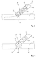
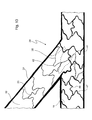
- Fig. 1 shows in a schematic view a vessel bifurcation 10 between a main vessel 11 and a secondary vessel 12.
- the secondary vessel 12 branches off at an angle 14 from the main vessel 11, into which it opens at a vessel opening 15.
- vessel bifurcation secondary vessel and main vessel are chosen only by way of example and are intended to make the description clearer.
- a vessel ramification may also be present in which a main vessel or secondary vessel divides up into two possibly smaller vessels.
- novel vessel supports explained below can be used in any type of such bifurcations.
- Fig. 2 shows schematically the situation that arises when known stents are inserted into the vessels 11, 12 and have a purely cylindrical shape in the expanded state.
- a main stent 16 sits in the main vessel 11, and a secondary stent 17 sits in the secondary vessel 12.
- Main stent 16 and secondary stent 17 each have a radially permeable and resilient structure, as is indicated by cross-hatching.
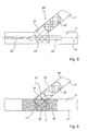
- the proximal segment 24 positioned in the vessel opening 15 lies partly in the secondary vessel 12 and partly in the main vessel 11 and supports the walls 19 and 27 there.
- This mechanical contact not only permits mechanical support of the areas 18 and 26, it also allows a medicament to be delivered there.
- Fig. 5 shows that, by way of a further guide wire 28, a novel main vessel support 29 can now be guided through the part of the proximal segment 24 lying in the main vessel 11, said main vessel support 29 sitting on a schematically indicated catheter 30 and being expanded after insertion, as is shown in Fig. 6 .
- the expanded main vessel support 29 has, in the area of the vessel opening 15, a central area 31 that is substantially free of vessel support material, such that the flow, for example of blood, through the vessel opening 15 is not impeded.
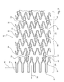
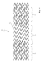
- Fig. 7 shows a schematic view of a flat projection of the secondary vessel support 22, the view being cut off at the distal end.
- the main section 25 is made up of a plurality of segments 32 that are arranged one behind another in the axial direction and that are interconnected via axially extending, undulating struts 33.
- the main section 25 directly adjoins the proximal segment 24 which, like the segments 32, has a closed ring structure and is thus able to ensure, after expansion, a good mechanical support of both vessels 11, 12 in the area of the vessel opening 15.
- the extent of the proximal segment 24 in the axial direction 39 is shorter as or the same length as the segments 32 of the main section 25, the number of loops 37 in the branch 35 of the proximal segment 24 is increased, such that a greater number of loops 37 lying alongside one another in the circumferential direction 40 serve as material storage that allow the extending of the proximal segment 24 into the main vessel 11.
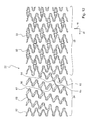
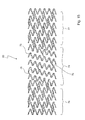
- Fig. 8 shows in another schematic view a flat projection of the main vessel support 29, the view being cut off at the distal end.
- the main vessel support 29 is made up of a plurality of segments 45 that are arranged one behind another in the axial direction 39 and that are each interconnected via two axially extending, undulating struts 46.
- the segments 45 each comprise a zigzag-shaped or wave-shaped branch 47 with loops 48 that lie alongside one another in the circumferential direction 40 and that have distal and proximal tips 49 and 51 in the axial direction 39.
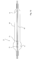
- Fig. 9 shows a schematic view of the expansion of the main vessel support 29 placed in the main vessel 11, whereby for reasons of clarity the secondary vessel support 22 is not shown.
- the main vessel support 29 is arranged on a balloon 52 of a catheter 53 which together form a balloon catheter known per se.
- the balloon 52 has already been expanded such that it has applied the main vessel support 29 against the wall 27 of the main vessel 11.
- Three X-ray markers 54 in total are arranged on the catheter 53 and are used for the exact positioning of the main vessel support 29 in the main vessel 11, such that the central area 31 comes to lie opposite the vessel opening 15.
- the balloon 52 has a central section 57 where the balloon 52 is approximately sphere-shaped and thus permits a greater expansion than the proximal and distal sections 56 and 55, respectively.
- the main vessel support 29 is positioned on the balloon 52 in such a way that its central area 31 lies on the central section 57, with the result that, upon expansion of the balloon 52, the central area 31 opens in the direction to the vessel opening 15.
- the balloon 52 is provided here with a coating 58 that contains a medicament, or it can also be coated directly with an active substance.
- the active substance or medicament is applied to the wall 27 where it can have, for example, an antiproliferative effect.
- the branches 47 and struts 46 can also be provided with such a coating, whereby the branches 47 and struts 46 can also have a porous surface serving as a reservoir for an active substance which, after implantation of the main vessel support 29, is gradually delivered to surrounding tissue.
- the secondary vessel support 22 and the balloon onto which it is crimped can be provided with such a coating, whereby the branches 35, 36 and struts 33, 34 of the secondary vessel support 22 can also have a porous surface that acts as a reservoir for active substance.
- Fig. 10 in a view similar to Fig. 6 , but with the vessels 11 and 12 extending in mirror symmetry compared to the arrangement in Figures 1 to 6 and 9, shows a schematic representation of the situation when the vessel supports 22, 29 from Figures 7 and 8 have been inserted into the vessel bifurcation 10, expanded and, if appropriate, further dilated. It can be seen that the proximal segment 24 lies in the vessel opening 15 and bears both on the inside of the secondary vessel 12 and also on the inside of the main vessel 11.
- the structural elements of the vessel supports 22 and 29 are provided with the same reference numbers as in Figures 7 and 8 .
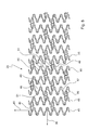
- Fig. 11 in a view similar to Fig. 7 , shows an alternative structure for the secondary vessel support 22 in which the proximal segment 24 extends in a spiral-shape from the main section 25, the view once again being cut off here at the distal end.
- Fig. 12 is a view similar to Fig. 11 showing that the proximal segment 24 additionally has, in its branch 61, struts 66 which extend in the axial direction 39 and which join together opposite tips 64 and 65, as a result of which improved stiffness is obtained in the axial direction 39.
- the balloon 68 sits in a manner known per se on a catheter 69 through which, during its advance into a vessel, there extends a guide wire not shown in Fig. 13 .
- the balloon 68 has a spherical shape in a section 72 and permits greater expansion there than in its remaining area.
- the secondary vessel support 22, which is not shown in Fig. 13 is positioned on the balloon 68 such that its proximal segment 24 lies on the section 72, with the result that, upon expansion of the balloon 68, the section 72 extends into the vessel opening 15 and the proximal segment 24 is positioned in the vessel opening in the manner that has already been described above.
- Three X-ray markers 73 in total are arranged on the catheter 69 and are used for exact positioning of the secondary vessel support 22 in the secondary vessel 12, such that the proximal segment 24 comes to lie in the vessel opening 15.
- Fig. 14 shows an alternative structure for the main vessel support 29 in which an approximately central area 74 is designed as a spiral-shaped branch 75, which extends between a proximal and a distal section 76 and 77, respectively.
- the sections 76 and 77 are designed like the main section 25 described with reference to Fig. 8 , while the branch 75 is of a design comparable to the branch 61 from Fig. 11 .
- spiral-shaped area 74 covers the area 26 of the wall 27 of the main vessel 11 opposite the vessel opening 15 such that spiral-shaped gaps as it were remain, which has the effect that the overlapping with the proximal segment 24 of the secondary vessel support 22 is still further reduced.
Landscapes
- Health & Medical Sciences (AREA)
- Engineering & Computer Science (AREA)
- Biomedical Technology (AREA)
- Life Sciences & Earth Sciences (AREA)
- General Health & Medical Sciences (AREA)
- Transplantation (AREA)
- Heart & Thoracic Surgery (AREA)
- Vascular Medicine (AREA)
- Cardiology (AREA)
- Animal Behavior & Ethology (AREA)
- Oral & Maxillofacial Surgery (AREA)
- Public Health (AREA)
- Veterinary Medicine (AREA)
- Physics & Mathematics (AREA)
- Optics & Photonics (AREA)
- Media Introduction/Drainage Providing Device (AREA)
- Prostheses (AREA)
Applications Claiming Priority (2)
| Application Number | Priority Date | Filing Date | Title |
|---|---|---|---|
| DE102007060497A DE102007060497A1 (de) | 2007-12-06 | 2007-12-06 | Implantierbare Gefäßstütze |
| EP08856311A EP2227192B1 (de) | 2007-12-06 | 2008-11-28 | Implantierbare gefässstütze |
Related Parent Applications (1)
| Application Number | Title | Priority Date | Filing Date |
|---|---|---|---|
| EP08856311.9 Division | 2008-11-28 |
Publications (2)
| Publication Number | Publication Date |
|---|---|
| EP2364677A1 true EP2364677A1 (de) | 2011-09-14 |
| EP2364677B1 EP2364677B1 (de) | 2013-03-27 |
Family
ID=40521650
Family Applications (2)
| Application Number | Title | Priority Date | Filing Date |
|---|---|---|---|
| EP11168874A Not-in-force EP2364677B1 (de) | 2007-12-06 | 2008-11-28 | Implantierbare Gefäßstütze |
| EP08856311A Not-in-force EP2227192B1 (de) | 2007-12-06 | 2008-11-28 | Implantierbare gefässstütze |
Family Applications After (1)
| Application Number | Title | Priority Date | Filing Date |
|---|---|---|---|
| EP08856311A Not-in-force EP2227192B1 (de) | 2007-12-06 | 2008-11-28 | Implantierbare gefässstütze |
Country Status (7)
| Country | Link |
|---|---|
| EP (2) | EP2364677B1 (de) |
| CN (1) | CN101932290A (de) |
| AT (1) | ATE525045T1 (de) |
| BR (1) | BRPI0820906A2 (de) |
| DE (1) | DE102007060497A1 (de) |
| ES (1) | ES2372335T3 (de) |
| WO (1) | WO2009071243A2 (de) |
Families Citing this family (6)
| Publication number | Priority date | Publication date | Assignee | Title |
|---|---|---|---|---|
| US10905572B2 (en) | 2016-11-14 | 2021-02-02 | Covidien Lp | Stent |
| US10449069B2 (en) * | 2016-11-14 | 2019-10-22 | Covidien Lp | Stent |
| US10258488B2 (en) | 2016-11-14 | 2019-04-16 | Covidien Lp | Stent |
| CN108451553A (zh) * | 2018-03-21 | 2018-08-28 | 成都康拓邦科技有限公司 | 脑卒中手术装置及系统 |
| CN110547897B (zh) * | 2019-09-04 | 2021-04-23 | 中国人民解放军总医院 | 血管支架装置 |
| JPWO2021161884A1 (de) * | 2020-02-14 | 2021-08-19 |
Citations (12)
| Publication number | Priority date | Publication date | Assignee | Title |
|---|---|---|---|---|
| FR2678508A1 (fr) * | 1991-07-04 | 1993-01-08 | Celsa Lg | Dispositif pour le renfort de vaisseaux du corps humain. |
| EP0875218A2 (de) | 1997-04-15 | 1998-11-04 | Advanced Cardiovascular Systems, Inc. | Wirkstoffhaltige poröse Metallprothesen |
| EP0950386A2 (de) | 1998-04-16 | 1999-10-20 | Cordis Corporation | Stent mit lokaler Rapamycin-Zufuhr |
| DE20200220U1 (de) | 2002-01-08 | 2002-03-21 | Translumina Gmbh | Stent |
| WO2002067815A1 (en) * | 2001-02-26 | 2002-09-06 | Scimed Life Systems, Inc. | Bifurcated stent |
| US20040186560A1 (en) | 2002-08-31 | 2004-09-23 | Tbd | Stent for bifurcated vessels |
| US20050177221A1 (en) | 2004-02-06 | 2005-08-11 | Mustapha Jihad A. | Ostial stent |
| US20050273149A1 (en) * | 2004-06-08 | 2005-12-08 | Tran Thomas T | Bifurcated stent delivery system |
| US20060025849A1 (en) | 2003-04-14 | 2006-02-02 | Aaron Kaplan | Vascular bifurcation prosthesis with multiple linked thin fronds |
| US20070016280A1 (en) * | 2005-07-14 | 2007-01-18 | Cappella, Inc. | Delivery System And Method Of Use For Deployment Of Self-Expandable Vascular Device |
| DE102006009996A1 (de) | 2006-03-03 | 2007-09-06 | Albrecht Dr. Elsässer | Stent |
| US20070276460A1 (en) * | 2003-04-14 | 2007-11-29 | Davis H R | Helical ostium support for treating vascular bifurcations |
Family Cites Families (6)
| Publication number | Priority date | Publication date | Assignee | Title |
|---|---|---|---|---|
| US5690642A (en) * | 1996-01-18 | 1997-11-25 | Cook Incorporated | Rapid exchange stent delivery balloon catheter |
| US6436104B2 (en) * | 1996-01-26 | 2002-08-20 | Cordis Corporation | Bifurcated axially flexible stent |
| DE19921788A1 (de) * | 1999-05-11 | 2000-11-16 | Jomed Implantate Gmbh | Vorrichtung zur Implantierung von Gefäßstützen |
| US20050049680A1 (en) * | 2003-09-03 | 2005-03-03 | Fischell Tim A. | Side branch stent with split proximal end |
| US20070112418A1 (en) * | 2005-11-14 | 2007-05-17 | Boston Scientific Scimed, Inc. | Stent with spiral side-branch support designs |
| US20070173925A1 (en) * | 2006-01-25 | 2007-07-26 | Cornova, Inc. | Flexible expandable stent |
-
2007
- 2007-12-06 DE DE102007060497A patent/DE102007060497A1/de not_active Withdrawn
-
2008
- 2008-11-28 WO PCT/EP2008/010102 patent/WO2009071243A2/en not_active Ceased
- 2008-11-28 AT AT08856311T patent/ATE525045T1/de not_active IP Right Cessation
- 2008-11-28 ES ES08856311T patent/ES2372335T3/es active Active
- 2008-11-28 CN CN2008801261069A patent/CN101932290A/zh active Pending
- 2008-11-28 BR BRPI0820906-5A patent/BRPI0820906A2/pt not_active IP Right Cessation
- 2008-11-28 EP EP11168874A patent/EP2364677B1/de not_active Not-in-force
- 2008-11-28 EP EP08856311A patent/EP2227192B1/de not_active Not-in-force
Patent Citations (12)
| Publication number | Priority date | Publication date | Assignee | Title |
|---|---|---|---|---|
| FR2678508A1 (fr) * | 1991-07-04 | 1993-01-08 | Celsa Lg | Dispositif pour le renfort de vaisseaux du corps humain. |
| EP0875218A2 (de) | 1997-04-15 | 1998-11-04 | Advanced Cardiovascular Systems, Inc. | Wirkstoffhaltige poröse Metallprothesen |
| EP0950386A2 (de) | 1998-04-16 | 1999-10-20 | Cordis Corporation | Stent mit lokaler Rapamycin-Zufuhr |
| WO2002067815A1 (en) * | 2001-02-26 | 2002-09-06 | Scimed Life Systems, Inc. | Bifurcated stent |
| DE20200220U1 (de) | 2002-01-08 | 2002-03-21 | Translumina Gmbh | Stent |
| US20040186560A1 (en) | 2002-08-31 | 2004-09-23 | Tbd | Stent for bifurcated vessels |
| US20060025849A1 (en) | 2003-04-14 | 2006-02-02 | Aaron Kaplan | Vascular bifurcation prosthesis with multiple linked thin fronds |
| US20070276460A1 (en) * | 2003-04-14 | 2007-11-29 | Davis H R | Helical ostium support for treating vascular bifurcations |
| US20050177221A1 (en) | 2004-02-06 | 2005-08-11 | Mustapha Jihad A. | Ostial stent |
| US20050273149A1 (en) * | 2004-06-08 | 2005-12-08 | Tran Thomas T | Bifurcated stent delivery system |
| US20070016280A1 (en) * | 2005-07-14 | 2007-01-18 | Cappella, Inc. | Delivery System And Method Of Use For Deployment Of Self-Expandable Vascular Device |
| DE102006009996A1 (de) | 2006-03-03 | 2007-09-06 | Albrecht Dr. Elsässer | Stent |
Also Published As
| Publication number | Publication date |
|---|---|
| ES2372335T3 (es) | 2012-01-18 |
| EP2227192A2 (de) | 2010-09-15 |
| DE102007060497A1 (de) | 2009-06-10 |
| EP2364677B1 (de) | 2013-03-27 |
| WO2009071243A2 (en) | 2009-06-11 |
| ATE525045T1 (de) | 2011-10-15 |
| WO2009071243A3 (en) | 2009-09-03 |
| BRPI0820906A2 (pt) | 2015-06-23 |
| CN101932290A (zh) | 2010-12-29 |
| EP2227192B1 (de) | 2011-09-21 |
Similar Documents
| Publication | Publication Date | Title |
|---|---|---|
| US7806923B2 (en) | Side branch stent having a proximal split ring | |
| EP1811923B1 (de) | Prothese zur platzierung bei einer gefässgabelung | |
| CA2474657C (en) | Anchoring device for an endoluminal prosthesis | |
| EP2268235B1 (de) | Stentprothese mit ausgewählten aufgeweiteten kronen | |
| US7846198B2 (en) | Vascular prosthesis and methods of use | |
| US20070219610A1 (en) | Stent with flap | |
| US9993329B2 (en) | Stent and stent graft prosthesis | |
| US20040267281A1 (en) | Delivery system for self-expandable diverter | |
| KR101949065B1 (ko) | 가요성 힌지를 구비한 스텐트 | |
| CN101641061A (zh) | 用于环锚固的自膨胀瓣膜的经心尖递送的系统和方法 | |
| JP2009515589A (ja) | らせん状の側枝支持設計を有するステント | |
| US20070088428A1 (en) | Intraluminal device with asymmetric cap portion | |
| JP2009528886A (ja) | 均一な側枝突部を備えた分岐型ステント | |
| EP2364677B1 (de) | Implantierbare Gefäßstütze | |
| JP2009507561A (ja) | クラウンステントアセンブリ | |
| JP2011504788A (ja) | 特定の口、カリナ、及び側枝の治療のための薬物用窪みを有する分岐ステント | |
| US20090259299A1 (en) | Side Branch Stent Having a Proximal Flexible Material Section | |
| KR101676265B1 (ko) | 중간 구조적 피쳐를 갖는 가요성 나선형 스텐트 | |
| US7901448B2 (en) | Vascular prothesis having interdigitating edges and methods of use | |
| US9186265B2 (en) | Implantable medical device having a means for positioning it at the precise site of a branching of a blood vessel such as a coronary artery | |
| CN113101023A (zh) | 一种特异性体内管腔植入物 | |
| EP3937860A1 (de) | Koronarostium-stent | |
| HK1110494A (en) | Prosthesis for placement at a vascular bifurcation | |
| HK1110494B (en) | Prosthesis for placement at a vascular bifurcation |
Legal Events
| Date | Code | Title | Description |
|---|---|---|---|
| PUAI | Public reference made under article 153(3) epc to a published international application that has entered the european phase |
Free format text: ORIGINAL CODE: 0009012 |
|
| AC | Divisional application: reference to earlier application |
Ref document number: 2227192 Country of ref document: EP Kind code of ref document: P |
|
| AK | Designated contracting states |
Kind code of ref document: A1 Designated state(s): AT BE BG CH CY CZ DE DK EE ES FI FR GB GR HR HU IE IS IT LI LT LU LV MC MT NL NO PL PT RO SE SI SK TR |
|
| 17P | Request for examination filed |
Effective date: 20120306 |
|
| RIC1 | Information provided on ipc code assigned before grant |
Ipc: A61F 2/90 20060101AFI20120628BHEP Ipc: A61F 2/06 20060101ALN20120628BHEP Ipc: A61F 2/00 20060101ALN20120628BHEP Ipc: A61F 2/88 20060101ALI20120628BHEP Ipc: A61F 2/84 20060101ALN20120628BHEP Ipc: A61F 2/82 20060101ALN20120628BHEP |
|
| GRAP | Despatch of communication of intention to grant a patent |
Free format text: ORIGINAL CODE: EPIDOSNIGR1 |
|
| GRAS | Grant fee paid |
Free format text: ORIGINAL CODE: EPIDOSNIGR3 |
|
| GRAA | (expected) grant |
Free format text: ORIGINAL CODE: 0009210 |
|
| RIC1 | Information provided on ipc code assigned before grant |
Ipc: A61F 2/88 20060101ALI20130211BHEP Ipc: A61F 2/90 20130101AFI20130211BHEP |
|
| AC | Divisional application: reference to earlier application |
Ref document number: 2227192 Country of ref document: EP Kind code of ref document: P |
|
| AK | Designated contracting states |
Kind code of ref document: B1 Designated state(s): AT BE BG CH CY CZ DE DK EE ES FI FR GB GR HR HU IE IS IT LI LT LU LV MC MT NL NO PL PT RO SE SI SK TR |
|
| REG | Reference to a national code |
Ref country code: GB Ref legal event code: FG4D |
|
| REG | Reference to a national code |
Ref country code: CH Ref legal event code: EP |
|
| REG | Reference to a national code |
Ref country code: AT Ref legal event code: REF Ref document number: 602882 Country of ref document: AT Kind code of ref document: T Effective date: 20130415 |
|
| REG | Reference to a national code |
Ref country code: IE Ref legal event code: FG4D |
|
| REG | Reference to a national code |
Ref country code: DE Ref legal event code: R096 Ref document number: 602008023378 Country of ref document: DE Effective date: 20130523 |
|
| PG25 | Lapsed in a contracting state [announced via postgrant information from national office to epo] |
Ref country code: SE Free format text: LAPSE BECAUSE OF FAILURE TO SUBMIT A TRANSLATION OF THE DESCRIPTION OR TO PAY THE FEE WITHIN THE PRESCRIBED TIME-LIMIT Effective date: 20130327 Ref country code: NO Free format text: LAPSE BECAUSE OF FAILURE TO SUBMIT A TRANSLATION OF THE DESCRIPTION OR TO PAY THE FEE WITHIN THE PRESCRIBED TIME-LIMIT Effective date: 20130627 Ref country code: BG Free format text: LAPSE BECAUSE OF FAILURE TO SUBMIT A TRANSLATION OF THE DESCRIPTION OR TO PAY THE FEE WITHIN THE PRESCRIBED TIME-LIMIT Effective date: 20130627 Ref country code: LT Free format text: LAPSE BECAUSE OF FAILURE TO SUBMIT A TRANSLATION OF THE DESCRIPTION OR TO PAY THE FEE WITHIN THE PRESCRIBED TIME-LIMIT Effective date: 20130327 |
|
| REG | Reference to a national code |
Ref country code: AT Ref legal event code: MK05 Ref document number: 602882 Country of ref document: AT Kind code of ref document: T Effective date: 20130327 |
|
| REG | Reference to a national code |
Ref country code: LT Ref legal event code: MG4D |
|
| PG25 | Lapsed in a contracting state [announced via postgrant information from national office to epo] |
Ref country code: SI Free format text: LAPSE BECAUSE OF FAILURE TO SUBMIT A TRANSLATION OF THE DESCRIPTION OR TO PAY THE FEE WITHIN THE PRESCRIBED TIME-LIMIT Effective date: 20130327 Ref country code: LV Free format text: LAPSE BECAUSE OF FAILURE TO SUBMIT A TRANSLATION OF THE DESCRIPTION OR TO PAY THE FEE WITHIN THE PRESCRIBED TIME-LIMIT Effective date: 20130327 Ref country code: FI Free format text: LAPSE BECAUSE OF FAILURE TO SUBMIT A TRANSLATION OF THE DESCRIPTION OR TO PAY THE FEE WITHIN THE PRESCRIBED TIME-LIMIT Effective date: 20130327 Ref country code: GR Free format text: LAPSE BECAUSE OF FAILURE TO SUBMIT A TRANSLATION OF THE DESCRIPTION OR TO PAY THE FEE WITHIN THE PRESCRIBED TIME-LIMIT Effective date: 20130628 |
|
| REG | Reference to a national code |
Ref country code: NL Ref legal event code: VDEP Effective date: 20130327 |
|
| PG25 | Lapsed in a contracting state [announced via postgrant information from national office to epo] |
Ref country code: BE Free format text: LAPSE BECAUSE OF FAILURE TO SUBMIT A TRANSLATION OF THE DESCRIPTION OR TO PAY THE FEE WITHIN THE PRESCRIBED TIME-LIMIT Effective date: 20130327 Ref country code: HR Free format text: LAPSE BECAUSE OF FAILURE TO SUBMIT A TRANSLATION OF THE DESCRIPTION OR TO PAY THE FEE WITHIN THE PRESCRIBED TIME-LIMIT Effective date: 20130327 |
|
| PG25 | Lapsed in a contracting state [announced via postgrant information from national office to epo] |
Ref country code: CZ Free format text: LAPSE BECAUSE OF FAILURE TO SUBMIT A TRANSLATION OF THE DESCRIPTION OR TO PAY THE FEE WITHIN THE PRESCRIBED TIME-LIMIT Effective date: 20130327 Ref country code: IS Free format text: LAPSE BECAUSE OF FAILURE TO SUBMIT A TRANSLATION OF THE DESCRIPTION OR TO PAY THE FEE WITHIN THE PRESCRIBED TIME-LIMIT Effective date: 20130727 Ref country code: AT Free format text: LAPSE BECAUSE OF FAILURE TO SUBMIT A TRANSLATION OF THE DESCRIPTION OR TO PAY THE FEE WITHIN THE PRESCRIBED TIME-LIMIT Effective date: 20130327 Ref country code: ES Free format text: LAPSE BECAUSE OF FAILURE TO SUBMIT A TRANSLATION OF THE DESCRIPTION OR TO PAY THE FEE WITHIN THE PRESCRIBED TIME-LIMIT Effective date: 20130708 Ref country code: PT Free format text: LAPSE BECAUSE OF FAILURE TO SUBMIT A TRANSLATION OF THE DESCRIPTION OR TO PAY THE FEE WITHIN THE PRESCRIBED TIME-LIMIT Effective date: 20130729 Ref country code: SK Free format text: LAPSE BECAUSE OF FAILURE TO SUBMIT A TRANSLATION OF THE DESCRIPTION OR TO PAY THE FEE WITHIN THE PRESCRIBED TIME-LIMIT Effective date: 20130327 Ref country code: RO Free format text: LAPSE BECAUSE OF FAILURE TO SUBMIT A TRANSLATION OF THE DESCRIPTION OR TO PAY THE FEE WITHIN THE PRESCRIBED TIME-LIMIT Effective date: 20130327 Ref country code: NL Free format text: LAPSE BECAUSE OF FAILURE TO SUBMIT A TRANSLATION OF THE DESCRIPTION OR TO PAY THE FEE WITHIN THE PRESCRIBED TIME-LIMIT Effective date: 20130327 Ref country code: EE Free format text: LAPSE BECAUSE OF FAILURE TO SUBMIT A TRANSLATION OF THE DESCRIPTION OR TO PAY THE FEE WITHIN THE PRESCRIBED TIME-LIMIT Effective date: 20130327 |
|
| PG25 | Lapsed in a contracting state [announced via postgrant information from national office to epo] |
Ref country code: CY Free format text: LAPSE BECAUSE OF FAILURE TO SUBMIT A TRANSLATION OF THE DESCRIPTION OR TO PAY THE FEE WITHIN THE PRESCRIBED TIME-LIMIT Effective date: 20130327 Ref country code: PL Free format text: LAPSE BECAUSE OF FAILURE TO SUBMIT A TRANSLATION OF THE DESCRIPTION OR TO PAY THE FEE WITHIN THE PRESCRIBED TIME-LIMIT Effective date: 20130327 |
|
| PG25 | Lapsed in a contracting state [announced via postgrant information from national office to epo] |
Ref country code: DK Free format text: LAPSE BECAUSE OF FAILURE TO SUBMIT A TRANSLATION OF THE DESCRIPTION OR TO PAY THE FEE WITHIN THE PRESCRIBED TIME-LIMIT Effective date: 20130327 |
|
| PLBE | No opposition filed within time limit |
Free format text: ORIGINAL CODE: 0009261 |
|
| STAA | Information on the status of an ep patent application or granted ep patent |
Free format text: STATUS: NO OPPOSITION FILED WITHIN TIME LIMIT |
|
| REG | Reference to a national code |
Ref country code: DE Ref legal event code: R081 Ref document number: 602008023378 Country of ref document: DE Owner name: TRANSLUMINA GMBH, DE Free format text: FORMER OWNERS: JOLINE GMBH & CO. KG, 72379 HECHINGEN, DE; TRANSLUMINA GMBH, 72379 HECHINGEN, DE Effective date: 20131212 Ref country code: DE Ref legal event code: R082 Ref document number: 602008023378 Country of ref document: DE Representative=s name: WITTE, WELLER & PARTNER PATENTANWAELTE MBB, DE Effective date: 20131212 Ref country code: DE Ref legal event code: R081 Ref document number: 602008023378 Country of ref document: DE Owner name: TRANSLUMINA GMBH, DE Free format text: FORMER OWNER: JOLINE GMBH & CO. KG, TRANSLUMINA GMBH, , DE Effective date: 20131212 |
|
| PG25 | Lapsed in a contracting state [announced via postgrant information from national office to epo] |
Ref country code: IT Free format text: LAPSE BECAUSE OF FAILURE TO SUBMIT A TRANSLATION OF THE DESCRIPTION OR TO PAY THE FEE WITHIN THE PRESCRIBED TIME-LIMIT Effective date: 20130327 |
|
| 26N | No opposition filed |
Effective date: 20140103 |
|
| REG | Reference to a national code |
Ref country code: DE Ref legal event code: R097 Ref document number: 602008023378 Country of ref document: DE Effective date: 20140103 |
|
| REG | Reference to a national code |
Ref country code: CH Ref legal event code: PL |
|
| GBPC | Gb: european patent ceased through non-payment of renewal fee |
Effective date: 20131128 |
|
| PG25 | Lapsed in a contracting state [announced via postgrant information from national office to epo] |
Ref country code: LI Free format text: LAPSE BECAUSE OF NON-PAYMENT OF DUE FEES Effective date: 20131130 Ref country code: CH Free format text: LAPSE BECAUSE OF NON-PAYMENT OF DUE FEES Effective date: 20131130 Ref country code: MC Free format text: LAPSE BECAUSE OF FAILURE TO SUBMIT A TRANSLATION OF THE DESCRIPTION OR TO PAY THE FEE WITHIN THE PRESCRIBED TIME-LIMIT Effective date: 20130327 |
|
| REG | Reference to a national code |
Ref country code: FR Ref legal event code: ST Effective date: 20140731 |
|
| REG | Reference to a national code |
Ref country code: IE Ref legal event code: MM4A |
|
| PG25 | Lapsed in a contracting state [announced via postgrant information from national office to epo] |
Ref country code: IE Free format text: LAPSE BECAUSE OF NON-PAYMENT OF DUE FEES Effective date: 20131128 |
|
| PG25 | Lapsed in a contracting state [announced via postgrant information from national office to epo] |
Ref country code: GB Free format text: LAPSE BECAUSE OF NON-PAYMENT OF DUE FEES Effective date: 20131128 Ref country code: FR Free format text: LAPSE BECAUSE OF NON-PAYMENT OF DUE FEES Effective date: 20131202 |
|
| PG25 | Lapsed in a contracting state [announced via postgrant information from national office to epo] |
Ref country code: TR Free format text: LAPSE BECAUSE OF FAILURE TO SUBMIT A TRANSLATION OF THE DESCRIPTION OR TO PAY THE FEE WITHIN THE PRESCRIBED TIME-LIMIT Effective date: 20130327 |
|
| PG25 | Lapsed in a contracting state [announced via postgrant information from national office to epo] |
Ref country code: HU Free format text: LAPSE BECAUSE OF FAILURE TO SUBMIT A TRANSLATION OF THE DESCRIPTION OR TO PAY THE FEE WITHIN THE PRESCRIBED TIME-LIMIT; INVALID AB INITIO Effective date: 20081128 Ref country code: LU Free format text: LAPSE BECAUSE OF NON-PAYMENT OF DUE FEES Effective date: 20131128 |
|
| PG25 | Lapsed in a contracting state [announced via postgrant information from national office to epo] |
Ref country code: MT Free format text: LAPSE BECAUSE OF FAILURE TO SUBMIT A TRANSLATION OF THE DESCRIPTION OR TO PAY THE FEE WITHIN THE PRESCRIBED TIME-LIMIT Effective date: 20130327 |
|
| PGFP | Annual fee paid to national office [announced via postgrant information from national office to epo] |
Ref country code: DE Payment date: 20230524 Year of fee payment: 15 |
|
| REG | Reference to a national code |
Ref country code: DE Ref legal event code: R119 Ref document number: 602008023378 Country of ref document: DE |
|
| PG25 | Lapsed in a contracting state [announced via postgrant information from national office to epo] |
Ref country code: DE Free format text: LAPSE BECAUSE OF NON-PAYMENT OF DUE FEES Effective date: 20240601 |
|
| PG25 | Lapsed in a contracting state [announced via postgrant information from national office to epo] |
Ref country code: DE Free format text: LAPSE BECAUSE OF NON-PAYMENT OF DUE FEES Effective date: 20240601 |