EP2364890B1 - Dispositif de sécurité pour remorques - Google Patents
Dispositif de sécurité pour remorques Download PDFInfo
- Publication number
- EP2364890B1 EP2364890B1 EP11001357A EP11001357A EP2364890B1 EP 2364890 B1 EP2364890 B1 EP 2364890B1 EP 11001357 A EP11001357 A EP 11001357A EP 11001357 A EP11001357 A EP 11001357A EP 2364890 B1 EP2364890 B1 EP 2364890B1
- Authority
- EP
- European Patent Office
- Prior art keywords
- ball
- brake output
- valve
- safety device
- switching
- Prior art date
- Legal status (The legal status is an assumption and is not a legal conclusion. Google has not performed a legal analysis and makes no representation as to the accuracy of the status listed.)
- Active
Links
Images



Classifications
-
- B—PERFORMING OPERATIONS; TRANSPORTING
- B60—VEHICLES IN GENERAL
- B60T—VEHICLE BRAKE CONTROL SYSTEMS OR PARTS THEREOF; BRAKE CONTROL SYSTEMS OR PARTS THEREOF, IN GENERAL; ARRANGEMENT OF BRAKING ELEMENTS ON VEHICLES IN GENERAL; PORTABLE DEVICES FOR PREVENTING UNWANTED MOVEMENT OF VEHICLES; VEHICLE MODIFICATIONS TO FACILITATE COOLING OF BRAKES
- B60T7/00—Brake-action initiating means
- B60T7/12—Brake-action initiating means for automatic initiation; for initiation not subject to will of driver or passenger
- B60T7/20—Brake-action initiating means for automatic initiation; for initiation not subject to will of driver or passenger specially for trailers, e.g. in case of uncoupling of or overrunning by trailer
-
- B—PERFORMING OPERATIONS; TRANSPORTING
- B60—VEHICLES IN GENERAL
- B60T—VEHICLE BRAKE CONTROL SYSTEMS OR PARTS THEREOF; BRAKE CONTROL SYSTEMS OR PARTS THEREOF, IN GENERAL; ARRANGEMENT OF BRAKING ELEMENTS ON VEHICLES IN GENERAL; PORTABLE DEVICES FOR PREVENTING UNWANTED MOVEMENT OF VEHICLES; VEHICLE MODIFICATIONS TO FACILITATE COOLING OF BRAKES
- B60T11/00—Transmitting braking action from initiating means to ultimate brake actuator without power assistance or drive or where such assistance or drive is irrelevant
- B60T11/10—Transmitting braking action from initiating means to ultimate brake actuator without power assistance or drive or where such assistance or drive is irrelevant transmitting by fluid means, e.g. hydraulic
- B60T11/107—Transmitting braking action from initiating means to ultimate brake actuator without power assistance or drive or where such assistance or drive is irrelevant transmitting by fluid means, e.g. hydraulic overrun brakes with fluid means
-
- B—PERFORMING OPERATIONS; TRANSPORTING
- B60—VEHICLES IN GENERAL
- B60T—VEHICLE BRAKE CONTROL SYSTEMS OR PARTS THEREOF; BRAKE CONTROL SYSTEMS OR PARTS THEREOF, IN GENERAL; ARRANGEMENT OF BRAKING ELEMENTS ON VEHICLES IN GENERAL; PORTABLE DEVICES FOR PREVENTING UNWANTED MOVEMENT OF VEHICLES; VEHICLE MODIFICATIONS TO FACILITATE COOLING OF BRAKES
- B60T17/00—Component parts, details, or accessories of power brake systems not covered by groups B60T8/00, B60T13/00 or B60T15/00, or presenting other characteristic features
- B60T17/18—Safety devices; Monitoring
Definitions
- the invention relates to a safety device for trailers of preferably agricultural tractor vehicles, which are provided with a hydraulically actuated brake system with a control unit, a supply input for the tractor with brake pressure zu adopteddem pressure fluid, a brake output in conjunction with at least one brake cylinder of the trailer, a hydraulic accumulator and a switchable valve assembly, which can be brought from a first switching state, in which it connects the supply input to the brake output, by means of a tension member, which is tensioned with increasing the distance between towing vehicle and trailer in a second switching state in which they connect from the brake output to the supply input, and connects the hydraulic accumulator to the brake output.
- the French patent publication 2 501 604 discloses such a device for triggering emergency braking of the trailer of an agricultural tractor in the event of an accident, in which increases the distance between towing vehicle and trailer, such as in the case of loosening the trailer hitch.
- a tension member for example in the form of connecting the towing vehicle with the trailer safety link chain
- the safety device is activated, wherein the biased with pressurized fluid hydraulic accumulator is connected to the brake system of the trailer and this supplied with brake pressure.
- the trailer thus remains in the braked state, even if there is a tearing off of the towing vehicle leading brake hose and the tension member, which has previously initiated the switching operation.
- valves used in the control unit are designed as slide valves. Since such valves are structurally associated with a leakage, there is a drop in the hydraulic accumulator made available brake pressure and thus after a while to a loss of braking effect with appropriate risk by the now unsecured trailer.
- the invention has the object to provide a safety device available, which in contrast offers increased reliability.
- a significant feature of the invention is that instead of slide valves in the valve assembly ball valves are provided which are mechanically coupled to each other, a ball valve, the connection between the supply input and brake output of the control unit and the second ball valve the connection between Brake output and hydraulic accumulator controls and wherein the ball valves are rotatably actuated to trigger an emergency braking by tightening the tension member against an attacking bias. Since with ball valves the ball is leak-free in its seat when the ball valve is closed, there is no risk of pressure reduction, so that the trailer after emergency braking remains in the secured state.
- At least the hydraulic accumulator associated second ball valve is provided with a check valve, which is pressure-actuated for fluid flow from the brake output to the hydraulic accumulator, it is ensured that the hydraulic accumulator during normal operation on the leading from the tractor to the supply port of the control unit brake hose is charged and thereby ensures that the brake pressure is available for emergency braking.
- the first ball valve is also provided with a check valve, which is pressure-actuated at the second switching position for a fluid flow from the supply input to the brake output.
- a check valve which is pressure-actuated at the second switching position for a fluid flow from the supply input to the brake output.
- ball valves are provided, in which the switching ball can be lifted against a spring force from its seated on a seat closing position to form an integrated check valve.
- At least one coil spring may be provided which surrounds the spindle of the respective ball valve and the spindle is applied with torque. With little space required is characterized a torque of sufficient strength achievable. Due to the compact design can be arranged without difficulty on each of the two ball valves, a coil spring.
- the arrangement may be made so that the ball valves are arranged with mutually coaxial spindle and a distance between them releasing and that within this distance, an actuating lever with two spindles is rotatably connected, acts at the free end of the tension member.
- the arrangement can be advantageously made so that the actuating lever, a detent and a thereto associated, biased to engage in the detent latch member are provided on a support of the ball valves stored and manually releasable from the latch to release the latch.
- the braked by the safety device trailer remains in the braked, secured state until the locking of the operating lever is released.
- the trailer can be handled without connection to the towing vehicle.
- manual actuation of the actuating lever and restoring the locking the trailer is in turn transferred to the braked state.
- the safety device can thus support or replace a mechanical handbrake of the trailer in additional function, especially since the latter operations, without connection to the towing vehicle, can be repeated several times, because thanks to the working without leakage valve assembly stored braking energy is available in the hydraulic accumulator.
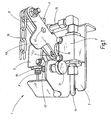
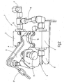
- Fig. 1 and 2 the control unit 1 of the safety device on a device carrier 3 on two ball valves 5 and 7, which are arranged in tandem with coaxial and facing each other rotary spindles 9 at a distance.
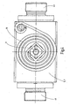
- the Fig. 3 illustrates the hydraulic circuit of the control unit 1 with a supply input P in conjunction with the ball valve 5, a line 13 to a Brake output V and a line 15 from the brake output V to the second ball valve 7 and the line 11th
- the spindles 9 of the ball valves 5 and 7 are connected to each other by means of an actuating lever 17 to rotate, which formed as a double lever and in Fig. 1 in the first switching state of the control unit corresponding pivot position and in Fig. 2 is shown in the position corresponding to the second switching state, in which an emergency braking is triggered.
- the ball valves 5 and 7 are in the in Fig. 1 biased, by means of coil springs 19. These are, as most clearly Fig. 4 can be seen, at the outlet end of the respective spindle 9 wound around them such that a torque acts on the spindles, which the actuating lever 17 in the in Fig. 1 pretensions shown pivot position.
- tension member 21 in the form of a link chain, which is anchored to the towing vehicle (not shown), pivots the actuating lever 17 against the bias in the in Fig. 2 shown pivot position when the tension member 21 tightens the distance to the towing vehicle and brings the spindles 9 of the ball valves 5, 7 in the switching position corresponding to the second switching state (emergency braking).
- control unit 1 is in the first switching state, corresponding to the normal driving operation, in which via the brake hose, not shown from the towing vehicle brake pressure from the supply input P forth on the ball valve located in the open position 5 to the brake output V and thus to the brake system of the trailer can be forwarded.
- the outflow of pressurized fluid from the hydraulic accumulator 4 is blocked by the ball valve 7 located in the blocking position.
- the ball valve 7 forms a check valve 25 in the blocking position, which, when the pressure at the brake output V (lines 13 and 15) is higher than the pressure in the hydraulic accumulator 4, is pressure-actuatable in order to charge the hydraulic accumulator 4.
- the ball valve 5 prevents the connection from the supply input P to the line 13 and thus to the brake output V.
- the second ball valve 7 connects the hydraulic accumulator 4 via the line 15 to the brake output V. so that the trailer is secured by emergency braking. If in this state the brake hose leading from the towing vehicle to the supply input P of the control unit 1 is not torn off, the hydraulic accumulator 4 can be recharged or charged from the towing vehicle via the additional check valve 27 assigned to the ball valve 5, for example, to perform an initial start-up of the trailer after maintenance, even when the safety device is in the activated state.
- the Fig. 5 to 7 clarify the construction of the ball valves 5, 7, which are provided with an integrated check valve 25, 27. It shows the Fig. 5 the side of the exit of the spindle 9 without the associated, in Fig. 4 visible spiral spring 19, so that in Fig. 5 the underlying under the coil spring 19 rotation limitation is visible, which consists of connected to the spindle 9 Begrenzersay 29 and stop 31.
- the switching ball 33 is not rigidly connected to the spindle 9, but from the spindle 9 via a cam slot 35 (FIGS. Fig. 6 ) rotatable.
- a cam slot 35 FIGS. Fig. 6
- Fig. 1 and 2 show a locking device for releasably locking the operating lever 17 in the second switching state corresponding pivot position.
- the latching device has in the lever 17 a detent in the form of a bore 45 and the device carrier 3 on a latch member 47 which is biased by a spring, not shown, in the advanced latch position, from which it is manually retractable against the spring force by a handle 51.
- On the actuating lever 17 is a slightly inclined control surface 49, at which the tip of the locking member 47 upon pivoting of the lever 17 in Fig. 1 and 2 starts to the left until the locking member 47 is incident in the bore 45 and thereby the lever 17 in the in Fig. 2 locked position shown corresponding to the second switching state.
- the lever 17 pivots in the in Fig. 1 shown pivot position under the influence of a torque generating coil spring 19 back.
Landscapes
- Engineering & Computer Science (AREA)
- Transportation (AREA)
- Mechanical Engineering (AREA)
- Valves And Accessory Devices For Braking Systems (AREA)
- Regulating Braking Force (AREA)
- Braking Systems And Boosters (AREA)
Claims (7)
- Dispositif de sécurité pour des remorques de véhicules de traction pouvant être utilisés, de préférence, en agriculture, qui sont pourvus d'un système de freinage pouvant être actionné hydrauliquement, comprenant une unité (1) de commande, qui a une entrée (P) d'alimentation en un fluide sous pression à envoyer avec une pression de freinage par le véhicule de traction, une sortie (V) de frein en liaison avec au moins un cylindre de frein de la remorque, un accumulateur (4) hydraulique et un agencement (5, 7) de vanne commutable, qui peut passer d'un premier état de commutation, dans lequel il met l'entrée (P) d'alimentation en communication avec la sortie (V) de frein, au moyen d'un élément (21) de traction, qui peut être tendu lorsque la distance entre le véhicule de traction et la remorque augmente, à un deuxième état de commutation, dans lequel il supprime la liaison allant de la sortie (V) de frein à l'entrée (P) d'alimentation et met l'accumulateur (4) hydraulique en communication avec la sortie (V) de frein, caractérisé en ce que l'agencement de vanne comporte deux robinets (5, 7) à bille, qui sont couplés mécaniquement et qui, par la tension de l'élément (21) de traction, peuvent être actionnés en rotation à l'encontre d'une précontrainte agissant sur eux, pour passer de leur première position de commutation, correspondante au premier état de commutation, à la deuxième autre position de commutation, en ce que l'un des robinets (5) à bille règle la communication entre l'entrée (P) d'alimentation et la sortie (V) de frein et le deuxième robinet (7) à bille règle la communication entre la sortie (V) de frein et l'accumulateur (4) hydraulique et en ce qu'au moins le deuxième robinet (7) à bille est pourvu d'un clapet anti-retour (25), qui peut être actionné par pression pour un courant de fluide allant de la sortie (V) de frein à l'accumulateur (4) hydraulique.
- Système de sécurité suivant la revendication 1, caractérisé en ce que le premier robinet (5) à bille est pourvu aussi d'un clapet anti-retour (27), qui dans la deuxième position de commutation peut être actionné par pression pour un courant de fluide allant de l'entrée (P) d'alimentation à la sortie (V) de frein.
- Système de sécurité suivant la revendication 1 ou 2, caractérisé en ce qu'il est prévu des robinets (5, 7) à bille, dans lesquels, pour la formation d'un clapet anti-retour (25, 27) intégré, la bille (33) peut, à l'encontre d'une force (39) de ressort, être soulevée de sa position de fermeture l'appliquant à un siège (37).
- Système de sécurité suivant l'une des revendications 1 à 3, caractérisé en ce qu'il est prévu un dispositif (45, 47) d'encliquetage amovible des robinets (5, 7) à bille, actionné en rotation dans la deuxième position de commutation.
- Système de sécurité suivant l'une des revendications 1 à 4, caractérisé en ce que, pour obtenir la précontrainte qui précontraint les robinets (5, 7) à bille dans la position de commutation correspondant au premier état de commutation, il est prévu au moins un ressort (19) spirale, qui entoure la broche (9) du robinet (5, 7) à bille concerné et qui applique un couple de rotation à la broche (9).
- Système de sécurité suivant l'une des revendications 1 à 5, caractérisé en ce que les robinets (5, 7) à bille sont disposés en ayant leurs broches (9) coaxiales l'une par rapport à l'autre et en laissant entre elles une distance et en ce que dans cette distance un levier (17) d'actionnement est solidaire en rotation des deux broches (9), levier dont l'extrémité libre est attaquée par l'élément (21) de traction.
- Système de sécurité suivant la revendication 6, caractérisé en ce que le dispositif d'encliquetage amovible des robinets (5, 7) à bille comporte sur le levier (17) d'actionnement un cran (45) et un élément (47) de verrouillage, qui est associé à celui-ci, qui est précontraint pour tomber dans le cran (45), qui est monté sur un support (3) des robinets (5, 7) à bille et qui peut être soulevé manuellement du cran (45) pour le désencliquetage.
Applications Claiming Priority (1)
| Application Number | Priority Date | Filing Date | Title |
|---|---|---|---|
| DE102010010836A DE102010010836A1 (de) | 2010-03-10 | 2010-03-10 | Sicherheitseinrichtung für Anhänger |
Publications (2)
| Publication Number | Publication Date |
|---|---|
| EP2364890A1 EP2364890A1 (fr) | 2011-09-14 |
| EP2364890B1 true EP2364890B1 (fr) | 2012-03-21 |
Family
ID=44141026
Family Applications (1)
| Application Number | Title | Priority Date | Filing Date |
|---|---|---|---|
| EP11001357A Active EP2364890B1 (fr) | 2010-03-10 | 2011-02-18 | Dispositif de sécurité pour remorques |
Country Status (3)
| Country | Link |
|---|---|
| EP (1) | EP2364890B1 (fr) |
| AT (1) | ATE550233T1 (fr) |
| DE (1) | DE102010010836A1 (fr) |
Families Citing this family (1)
| Publication number | Priority date | Publication date | Assignee | Title |
|---|---|---|---|---|
| GB2555906B (en) * | 2016-08-19 | 2021-09-29 | Innealtoireacht Ui Loinsigh Teo | A Trailer Breakaway Brake System |
Family Cites Families (5)
| Publication number | Priority date | Publication date | Assignee | Title |
|---|---|---|---|---|
| GB698319A (en) * | 1951-07-31 | 1953-10-14 | Westinghouse Brake & Signal | Improvements relating to tractor-trailer fluid pressure braking apparatus |
| US2834437A (en) * | 1956-08-22 | 1958-05-13 | Berryman O Davids | Automatic brake applicator |
| DE3008067A1 (de) * | 1980-03-03 | 1981-09-24 | G.L. Rexroth Gmbh, 8770 Lohr | Ausloesevorrichtung fuer ein abreissventil |
| FR2501604A1 (fr) | 1981-03-10 | 1982-09-17 | Henrion Ets | Dispositif de securite de freinage pour une remorque de tracteur agricole |
| GB9904290D0 (en) * | 1999-02-25 | 1999-04-21 | Ford New Holland Nv | Fail safe braking system |
-
2010
- 2010-03-10 DE DE102010010836A patent/DE102010010836A1/de not_active Withdrawn
-
2011
- 2011-02-18 EP EP11001357A patent/EP2364890B1/fr active Active
- 2011-02-18 AT AT11001357T patent/ATE550233T1/de active
Also Published As
| Publication number | Publication date |
|---|---|
| DE102010010836A1 (de) | 2011-09-15 |
| EP2364890A1 (fr) | 2011-09-14 |
| ATE550233T1 (de) | 2012-04-15 |
Similar Documents
| Publication | Publication Date | Title |
|---|---|---|
| DE102004045988B3 (de) | Anzeige zur Signalisierung der Nichtverriegelung einer klappbaren Rückenlehne eines Kraftfahrzeugsitzes | |
| EP3515770B1 (fr) | Arrangement de vannes de frein de stationnement pour commander un frein d'immobilisation à ressort accumulateur | |
| EP2836406B1 (fr) | Système d'air comprimé pour l'approvisionnement d'air d'un camion | |
| DE102012107203B4 (de) | Pneumatische Bremseinrichtung eines Fahrzeugs mit vom Parkbremsventil zwangsgesteuerter Interlock-Einrichtung | |
| DE102016210874B4 (de) | Vorrichtung zum Betätigen einer Parksperre eines Automatikgetriebes, sowie Parksperreneinrichtung für ein solches Automatikgetriebe | |
| DE102021111206A1 (de) | Automatische Zugkupplung und Verfahren zum Entkuppeln einer automatischen Zugkupplung | |
| DE1218891B (de) | Druckmittelbremsanlage fuer Fahrzeuge, insbesondere Kraftfahrzeuge | |
| DE102009036783B4 (de) | Nothahn, Türbetätigungsvorrichtung, Fahrzeugtüranlage, Fahrzeug und Verfahren zum Betreiben einer Fahrzeugtüranlage | |
| EP2364890B1 (fr) | Dispositif de sécurité pour remorques | |
| EP0830997B1 (fr) | Approvisionnement énergétique pour systèmes de freinage pneumatiques de véhicules | |
| DE2500903A1 (de) | Steuerungssystem fuer eine bremse | |
| DE102015106171A1 (de) | Hydraulisch betätigbare Pneumatikventileinrichtung | |
| DE2546557C2 (de) | Handbremsventil | |
| DE3045455C2 (de) | Hydraulische Anhänger-Bremsanlage für Nutzfahrzeuge | |
| WO2006084445A2 (fr) | Porte comprenant un frein de porte | |
| DE3630892C2 (fr) | ||
| DE2339397C3 (de) | Zweileitungs-Druckluftbremsanlage für Anhängerfahrzeuge, insbesondere Zweikreis-Bremsanlage | |
| DE102013010031A1 (de) | Kupplungskopfeinheit für ein Nutzfahrzeug und Verfahren zum Ankoppeln einer Versorgungsleitung und einer Steuerleitung an eine pneumatisch betriebene Bremsanlage | |
| DE102006035140B3 (de) | Schaltungsanordnung für eine Druckmittelbetätigung einer Tür | |
| DE2501070B2 (de) | Zweileitungs-druckluftbremsanlage fuer kraftfahrzeuge mit anhaenger, mit einem anhaengersteuerventil und einem sperrventil | |
| DE2260714C3 (de) | Vorrichtung zur Verriegelung des hinteren Endes des Kippfahrerhauses eines Lastkraftwagens | |
| AT409112B (de) | Hydraulische anordnung zur betätigung von beweglichen teilen an fahrzeugen, und vorspannventil für diese anordnung | |
| DE102015210448B4 (de) | Bremsvorrichtung mit einem Sonderbremszustand, Bremssystem, Fahrzeug und Verfahren | |
| DE2461712C2 (de) | Hydraulische drehvorrichtung fuer einen drehpflug | |
| DE102018122518A1 (de) | Bremszylinder mit einer Verriegelungsvorrichtung zur mechanischen Bremskraftverriegelung |
Legal Events
| Date | Code | Title | Description |
|---|---|---|---|
| PUAI | Public reference made under article 153(3) epc to a published international application that has entered the european phase |
Free format text: ORIGINAL CODE: 0009012 |
|
| 17P | Request for examination filed |
Effective date: 20110716 |
|
| AK | Designated contracting states |
Kind code of ref document: A1 Designated state(s): AL AT BE BG CH CY CZ DE DK EE ES FI FR GB GR HR HU IE IS IT LI LT LU LV MC MK MT NL NO PL PT RO RS SE SI SK SM TR |
|
| AX | Request for extension of the european patent |
Extension state: BA ME |
|
| GRAP | Despatch of communication of intention to grant a patent |
Free format text: ORIGINAL CODE: EPIDOSNIGR1 |
|
| GRAS | Grant fee paid |
Free format text: ORIGINAL CODE: EPIDOSNIGR3 |
|
| GRAA | (expected) grant |
Free format text: ORIGINAL CODE: 0009210 |
|
| AK | Designated contracting states |
Kind code of ref document: B1 Designated state(s): AL AT BE BG CH CY CZ DE DK EE ES FI FR GB GR HR HU IE IS IT LI LT LU LV MC MK MT NL NO PL PT RO RS SE SI SK SM TR |
|
| REG | Reference to a national code |
Ref country code: GB Ref legal event code: FG4D Free format text: NOT ENGLISH |
|
| REG | Reference to a national code |
Ref country code: CH Ref legal event code: EP |
|
| REG | Reference to a national code |
Ref country code: IE Ref legal event code: FG4D Free format text: LANGUAGE OF EP DOCUMENT: GERMAN |
|
| REG | Reference to a national code |
Ref country code: AT Ref legal event code: REF Ref document number: 550233 Country of ref document: AT Kind code of ref document: T Effective date: 20120415 |
|
| REG | Reference to a national code |
Ref country code: DE Ref legal event code: R096 Ref document number: 502011000006 Country of ref document: DE Effective date: 20120516 |
|
| REG | Reference to a national code |
Ref country code: NL Ref legal event code: VDEP Effective date: 20120321 |
|
| PG25 | Lapsed in a contracting state [announced via postgrant information from national office to epo] |
Ref country code: LT Free format text: LAPSE BECAUSE OF FAILURE TO SUBMIT A TRANSLATION OF THE DESCRIPTION OR TO PAY THE FEE WITHIN THE PRESCRIBED TIME-LIMIT Effective date: 20120321 Ref country code: NO Free format text: LAPSE BECAUSE OF FAILURE TO SUBMIT A TRANSLATION OF THE DESCRIPTION OR TO PAY THE FEE WITHIN THE PRESCRIBED TIME-LIMIT Effective date: 20120621 Ref country code: HR Free format text: LAPSE BECAUSE OF FAILURE TO SUBMIT A TRANSLATION OF THE DESCRIPTION OR TO PAY THE FEE WITHIN THE PRESCRIBED TIME-LIMIT Effective date: 20120321 |
|
| LTIE | Lt: invalidation of european patent or patent extension |
Effective date: 20120321 |
|
| PG25 | Lapsed in a contracting state [announced via postgrant information from national office to epo] |
Ref country code: FI Free format text: LAPSE BECAUSE OF FAILURE TO SUBMIT A TRANSLATION OF THE DESCRIPTION OR TO PAY THE FEE WITHIN THE PRESCRIBED TIME-LIMIT Effective date: 20120321 Ref country code: RS Free format text: LAPSE BECAUSE OF FAILURE TO SUBMIT A TRANSLATION OF THE DESCRIPTION OR TO PAY THE FEE WITHIN THE PRESCRIBED TIME-LIMIT Effective date: 20120321 Ref country code: LV Free format text: LAPSE BECAUSE OF FAILURE TO SUBMIT A TRANSLATION OF THE DESCRIPTION OR TO PAY THE FEE WITHIN THE PRESCRIBED TIME-LIMIT Effective date: 20120321 Ref country code: GR Free format text: LAPSE BECAUSE OF FAILURE TO SUBMIT A TRANSLATION OF THE DESCRIPTION OR TO PAY THE FEE WITHIN THE PRESCRIBED TIME-LIMIT Effective date: 20120622 |
|
| PG25 | Lapsed in a contracting state [announced via postgrant information from national office to epo] |
Ref country code: CY Free format text: LAPSE BECAUSE OF FAILURE TO SUBMIT A TRANSLATION OF THE DESCRIPTION OR TO PAY THE FEE WITHIN THE PRESCRIBED TIME-LIMIT Effective date: 20120321 |
|
| PG25 | Lapsed in a contracting state [announced via postgrant information from national office to epo] |
Ref country code: SE Free format text: LAPSE BECAUSE OF FAILURE TO SUBMIT A TRANSLATION OF THE DESCRIPTION OR TO PAY THE FEE WITHIN THE PRESCRIBED TIME-LIMIT Effective date: 20120321 Ref country code: IS Free format text: LAPSE BECAUSE OF FAILURE TO SUBMIT A TRANSLATION OF THE DESCRIPTION OR TO PAY THE FEE WITHIN THE PRESCRIBED TIME-LIMIT Effective date: 20120721 Ref country code: EE Free format text: LAPSE BECAUSE OF FAILURE TO SUBMIT A TRANSLATION OF THE DESCRIPTION OR TO PAY THE FEE WITHIN THE PRESCRIBED TIME-LIMIT Effective date: 20120321 Ref country code: RO Free format text: LAPSE BECAUSE OF FAILURE TO SUBMIT A TRANSLATION OF THE DESCRIPTION OR TO PAY THE FEE WITHIN THE PRESCRIBED TIME-LIMIT Effective date: 20120321 Ref country code: CZ Free format text: LAPSE BECAUSE OF FAILURE TO SUBMIT A TRANSLATION OF THE DESCRIPTION OR TO PAY THE FEE WITHIN THE PRESCRIBED TIME-LIMIT Effective date: 20120321 Ref country code: PL Free format text: LAPSE BECAUSE OF FAILURE TO SUBMIT A TRANSLATION OF THE DESCRIPTION OR TO PAY THE FEE WITHIN THE PRESCRIBED TIME-LIMIT Effective date: 20120321 Ref country code: SI Free format text: LAPSE BECAUSE OF FAILURE TO SUBMIT A TRANSLATION OF THE DESCRIPTION OR TO PAY THE FEE WITHIN THE PRESCRIBED TIME-LIMIT Effective date: 20120321 |
|
| PG25 | Lapsed in a contracting state [announced via postgrant information from national office to epo] |
Ref country code: SK Free format text: LAPSE BECAUSE OF FAILURE TO SUBMIT A TRANSLATION OF THE DESCRIPTION OR TO PAY THE FEE WITHIN THE PRESCRIBED TIME-LIMIT Effective date: 20120321 |
|
| PLBE | No opposition filed within time limit |
Free format text: ORIGINAL CODE: 0009261 |
|
| STAA | Information on the status of an ep patent application or granted ep patent |
Free format text: STATUS: NO OPPOSITION FILED WITHIN TIME LIMIT |
|
| PG25 | Lapsed in a contracting state [announced via postgrant information from national office to epo] |
Ref country code: DK Free format text: LAPSE BECAUSE OF FAILURE TO SUBMIT A TRANSLATION OF THE DESCRIPTION OR TO PAY THE FEE WITHIN THE PRESCRIBED TIME-LIMIT Effective date: 20120321 Ref country code: NL Free format text: LAPSE BECAUSE OF FAILURE TO SUBMIT A TRANSLATION OF THE DESCRIPTION OR TO PAY THE FEE WITHIN THE PRESCRIBED TIME-LIMIT Effective date: 20120321 |
|
| 26N | No opposition filed |
Effective date: 20130102 |
|
| REG | Reference to a national code |
Ref country code: DE Ref legal event code: R097 Ref document number: 502011000006 Country of ref document: DE Effective date: 20130102 |
|
| PG25 | Lapsed in a contracting state [announced via postgrant information from national office to epo] |
Ref country code: BG Free format text: LAPSE BECAUSE OF FAILURE TO SUBMIT A TRANSLATION OF THE DESCRIPTION OR TO PAY THE FEE WITHIN THE PRESCRIBED TIME-LIMIT Effective date: 20120621 |
|
| BERE | Be: lapsed |
Owner name: HYDAC ACCESSORIES G.M.B.H. Effective date: 20130228 |
|
| PG25 | Lapsed in a contracting state [announced via postgrant information from national office to epo] |
Ref country code: MC Free format text: LAPSE BECAUSE OF NON-PAYMENT OF DUE FEES Effective date: 20130228 |
|
| PG25 | Lapsed in a contracting state [announced via postgrant information from national office to epo] |
Ref country code: ES Free format text: LAPSE BECAUSE OF FAILURE TO SUBMIT A TRANSLATION OF THE DESCRIPTION OR TO PAY THE FEE WITHIN THE PRESCRIBED TIME-LIMIT Effective date: 20120702 |
|
| REG | Reference to a national code |
Ref country code: IE Ref legal event code: MM4A |
|
| PG25 | Lapsed in a contracting state [announced via postgrant information from national office to epo] |
Ref country code: BE Free format text: LAPSE BECAUSE OF NON-PAYMENT OF DUE FEES Effective date: 20130228 Ref country code: AL Free format text: LAPSE BECAUSE OF FAILURE TO SUBMIT A TRANSLATION OF THE DESCRIPTION OR TO PAY THE FEE WITHIN THE PRESCRIBED TIME-LIMIT Effective date: 20120321 Ref country code: IE Free format text: LAPSE BECAUSE OF NON-PAYMENT OF DUE FEES Effective date: 20130218 |
|
| PG25 | Lapsed in a contracting state [announced via postgrant information from national office to epo] |
Ref country code: MT Free format text: LAPSE BECAUSE OF FAILURE TO SUBMIT A TRANSLATION OF THE DESCRIPTION OR TO PAY THE FEE WITHIN THE PRESCRIBED TIME-LIMIT Effective date: 20120321 |
|
| REG | Reference to a national code |
Ref country code: CH Ref legal event code: PL |
|
| PG25 | Lapsed in a contracting state [announced via postgrant information from national office to epo] |
Ref country code: LI Free format text: LAPSE BECAUSE OF NON-PAYMENT OF DUE FEES Effective date: 20140228 Ref country code: CH Free format text: LAPSE BECAUSE OF NON-PAYMENT OF DUE FEES Effective date: 20140228 |
|
| PG25 | Lapsed in a contracting state [announced via postgrant information from national office to epo] |
Ref country code: SM Free format text: LAPSE BECAUSE OF FAILURE TO SUBMIT A TRANSLATION OF THE DESCRIPTION OR TO PAY THE FEE WITHIN THE PRESCRIBED TIME-LIMIT Effective date: 20120321 |
|
| PG25 | Lapsed in a contracting state [announced via postgrant information from national office to epo] |
Ref country code: TR Free format text: LAPSE BECAUSE OF FAILURE TO SUBMIT A TRANSLATION OF THE DESCRIPTION OR TO PAY THE FEE WITHIN THE PRESCRIBED TIME-LIMIT Effective date: 20120321 |
|
| PG25 | Lapsed in a contracting state [announced via postgrant information from national office to epo] |
Ref country code: MK Free format text: LAPSE BECAUSE OF FAILURE TO SUBMIT A TRANSLATION OF THE DESCRIPTION OR TO PAY THE FEE WITHIN THE PRESCRIBED TIME-LIMIT Effective date: 20120321 Ref country code: HU Free format text: LAPSE BECAUSE OF FAILURE TO SUBMIT A TRANSLATION OF THE DESCRIPTION OR TO PAY THE FEE WITHIN THE PRESCRIBED TIME-LIMIT; INVALID AB INITIO Effective date: 20110218 Ref country code: LU Free format text: LAPSE BECAUSE OF NON-PAYMENT OF DUE FEES Effective date: 20130218 |
|
| GBPC | Gb: european patent ceased through non-payment of renewal fee |
Effective date: 20150218 |
|
| REG | Reference to a national code |
Ref country code: FR Ref legal event code: PLFP Year of fee payment: 6 |
|
| PG25 | Lapsed in a contracting state [announced via postgrant information from national office to epo] |
Ref country code: GB Free format text: LAPSE BECAUSE OF NON-PAYMENT OF DUE FEES Effective date: 20150218 |
|
| PG25 | Lapsed in a contracting state [announced via postgrant information from national office to epo] |
Ref country code: PT Free format text: LAPSE BECAUSE OF FAILURE TO SUBMIT A TRANSLATION OF THE DESCRIPTION OR TO PAY THE FEE WITHIN THE PRESCRIBED TIME-LIMIT Effective date: 20120321 |
|
| REG | Reference to a national code |
Ref country code: FR Ref legal event code: PLFP Year of fee payment: 7 |
|
| REG | Reference to a national code |
Ref country code: FR Ref legal event code: PLFP Year of fee payment: 8 |
|
| PGFP | Annual fee paid to national office [announced via postgrant information from national office to epo] |
Ref country code: IT Payment date: 20190213 Year of fee payment: 9 |
|
| PGFP | Annual fee paid to national office [announced via postgrant information from national office to epo] |
Ref country code: AT Payment date: 20190228 Year of fee payment: 9 |
|
| REG | Reference to a national code |
Ref country code: AT Ref legal event code: MM01 Ref document number: 550233 Country of ref document: AT Kind code of ref document: T Effective date: 20200218 |
|
| PG25 | Lapsed in a contracting state [announced via postgrant information from national office to epo] |
Ref country code: AT Free format text: LAPSE BECAUSE OF NON-PAYMENT OF DUE FEES Effective date: 20200218 |
|
| PG25 | Lapsed in a contracting state [announced via postgrant information from national office to epo] |
Ref country code: IT Free format text: LAPSE BECAUSE OF NON-PAYMENT OF DUE FEES Effective date: 20200218 |
|
| PGFP | Annual fee paid to national office [announced via postgrant information from national office to epo] |
Ref country code: DE Payment date: 20260228 Year of fee payment: 16 |
|
| PGFP | Annual fee paid to national office [announced via postgrant information from national office to epo] |
Ref country code: FR Payment date: 20260213 Year of fee payment: 16 |