EP2364897A2 - Contrôleur de direction assistée électrique et système de direction assistée électrique - Google Patents
Contrôleur de direction assistée électrique et système de direction assistée électrique Download PDFInfo
- Publication number
- EP2364897A2 EP2364897A2 EP11155812A EP11155812A EP2364897A2 EP 2364897 A2 EP2364897 A2 EP 2364897A2 EP 11155812 A EP11155812 A EP 11155812A EP 11155812 A EP11155812 A EP 11155812A EP 2364897 A2 EP2364897 A2 EP 2364897A2
- Authority
- EP
- European Patent Office
- Prior art keywords
- torque
- detector
- motor
- tmain
- power steering
- Prior art date
- Legal status (The legal status is an assumption and is not a legal conclusion. Google has not performed a legal analysis and makes no representation as to the accuracy of the status listed.)
- Granted
Links
Images


Classifications
-
- B—PERFORMING OPERATIONS; TRANSPORTING
- B62—LAND VEHICLES FOR TRAVELLING OTHERWISE THAN ON RAILS
- B62D—MOTOR VEHICLES; TRAILERS
- B62D5/00—Power-assisted or power-driven steering
- B62D5/04—Power-assisted or power-driven steering electrical, e.g. using an electric servo-motor connected to, or forming part of, the steering gear
- B62D5/0457—Power-assisted or power-driven steering electrical, e.g. using an electric servo-motor connected to, or forming part of, the steering gear characterised by control features of the drive means as such
- B62D5/0481—Power-assisted or power-driven steering electrical, e.g. using an electric servo-motor connected to, or forming part of, the steering gear characterised by control features of the drive means as such monitoring the steering system, e.g. failures
- B62D5/049—Power-assisted or power-driven steering electrical, e.g. using an electric servo-motor connected to, or forming part of, the steering gear characterised by control features of the drive means as such monitoring the steering system, e.g. failures detecting sensor failures
-
- B—PERFORMING OPERATIONS; TRANSPORTING
- B62—LAND VEHICLES FOR TRAVELLING OTHERWISE THAN ON RAILS
- B62D—MOTOR VEHICLES; TRAILERS
- B62D5/00—Power-assisted or power-driven steering
- B62D5/04—Power-assisted or power-driven steering electrical, e.g. using an electric servo-motor connected to, or forming part of, the steering gear
- B62D5/0457—Power-assisted or power-driven steering electrical, e.g. using an electric servo-motor connected to, or forming part of, the steering gear characterised by control features of the drive means as such
- B62D5/0481—Power-assisted or power-driven steering electrical, e.g. using an electric servo-motor connected to, or forming part of, the steering gear characterised by control features of the drive means as such monitoring the steering system, e.g. failures
- B62D5/0484—Power-assisted or power-driven steering electrical, e.g. using an electric servo-motor connected to, or forming part of, the steering gear characterised by control features of the drive means as such monitoring the steering system, e.g. failures for reaction to failures, e.g. limp home
Definitions
- the present invention relates to electric power steering controllers and electric power steering systems in general and particularly to an electric power steering controller and an electric power steering system effective in detecting failures of a main microcomputer that controls electric power steering.
- a widely used method for detecting failures of a main microcomputer involves the use of a monitoring microcomputer, thereby allowing a cross-check between the two microcomputers.
- Another common method is to make a main microcomputer dually redundant for comparison between two outputs.
- a microcomputer can perform a self-check by configuring its logic circuits and datapath with redundant code logic such as parity and error detection and correction codes or by providing the microcomputer with an inspection circuit.
- JP-2005-315840-A a torque sensor is used to detect abnormalities of a main microcomputer.
- the torque sensor detects an abnormality of the main microcomputer when the torque sensor detects excessive torque.
- a power steering system uses power to provide steering assistance to the driver. If the system should operate against the will of the driver due to a system failure, the driver would attempt to resist this by applying a larger steering force (torque) to the steering wheel than usual.
- the method of JP-2005-315840-A uses the torque sensor to detect an excessive steering force during failure of the power steering system. After the detection, the system stops the steering assistance, thereby achieving fail-safe operation.
- the method of JP-2005-315840-A can detect not only abnormalities of the main microcomputer but abnormalities of an inverter predriver and an inverter and bugs of control software as well.
- JP-2005-315840-A still requires consideration of how to deal with failures of the torque sensor, which detects the steering force exerted by the driver. If abnormalities of the torque sensor cannot be detected, an abnormality of the torque sensor may be misjudged as an abnormality of the main microcomputer. Because a power steering system requires different operations for torque-sensor abnormalities and main-microcomputer abnormalities, it has to distinguish between them.
- An object of the present invention is thus to provide an electric power steering controller and an electric power steering system that allow appropriate system control even when the operation of a torque sensor is abnormal.
- one preferred mode of the present invention is as follows:
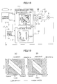
- FIGS. 1 through 13 Described now with reference to FIGS. 1 through 13 is the configuration and operation of an electric power steering controller according to Embodiment 1 of the invention.
- First described with reference to FIG. 1 is the configuration of an electric power steering system incorporating the power steering controller of Embodiment 1.
- FIG. 1 is a block diagram of that system.
- a steering wheel 7 and a torque sensor 2 are connected by a steering shaft 15.
- the torque sensor 2 is designed to detect the steering force (torque) exerted by the driver and output a first torque signal Tmain and a second torque signal Tsub, both of which represent the steering force. These signals Tmain and Tsub will later be described in detail with reference to FIG. 3 .
- the torque sensor 2 will also be described later with reference to FIGS. 2 , 4, and 5 .
- the two torque signals Tmain and Tsub are input to a main microcomputer 1-1 and also to an external device 1-2.
- the main microcomputer 1-1 includes a controller 100 and a torque sensor abnormality detector 101.
- the controller 100 outputs motor drive signals 3 to a three-phase inverter 5 based on the first torque signal Tmain or the second torque signal Tsub and on a magnetic pole signal detected by a magnetic pole sensor installed in a motor 6.
- the motor 6 is implemented by a three-phase synchronous motor.
- the motor drive signals 3 comprises six such signals although FIG. 1 depicts, for simplification purposes, the controller 100 as transmitting only three motor drive signals 3 to the three-phase inverter 5. This is because the three-phase inverter 5 includes, for each phase, a pair of an upper arm and a lower arm, each of the arms having a switch.
- the three-phase inverter 5 (drive circuit) supplies drive current to the motor 6 in response to the motor drive signals 3 received from the main microcomputer 1-1.
- the motor 6 applies assistive torque to the steering shaft 15. This output of the motor 6 is transmitted to the steering shaft 15 via a decelerator not illustrated.
- the motor 6 may instead be a DC motor.
- the three-phase inverter 5 is replaced by a DC drive circuit for feeding direct current to the DC motor in response to the motor drive signals 3.
- the main microcomputer 1-1 includes the torque sensor abnormality detector 101.
- This detector 101 detects an abnormality of the torque sensor 2 by obtaining the difference between the first torque signal Tmain and the second torque signal Tsub.
- the operation of the torque sensor abnormality detector 101 will later be described with reference to FIGS. 10 and 11 .
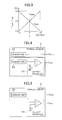
- FIG. 2 is a block diagram illustrating the configuration of the torque sensor 2 used for the power steering system of Embodiment 1.
- FIG. 3 is a graph illustrating the output characteristics of the torque sensor 2.
- the torque sensor 2 includes a first sensor unit 2A, a second sensor unit 2B, and an output adjuster 2C.
- the first sensor unit 2A outputs the first torque signal Tmain the voltage of which is shown in FIG. 3 .
- the first sensor unit 2A outputs a voltage of 2.5 V.
- the voltage of the first torque signal Tmain increases linearly.
- the voltage of the first torque signal Tmain reaches 5 V.
- the voltage of the first torque signal Tmain decreases linearly.
- the voltage ⁇ reaches 0 V.
- the output voltage of the second unit sensor 2B is the same as the voltage of the first torque signal Tmain.
- the output of the second sensor unit 2B is input to the output adjuster 2C that includes a differential amplifier. Applied to the positive input of the differential amplifier is DC voltage V1 which is supplied from a DC power supply. This voltage V1 is a voltage of 5V.
- the negative input of the differential amplifier receives the output of the second sensor unit 2B.
- the output of the output adjuster 2C is a signal the voltage of which is 5V minus the voltage of the first torque signal Tmain of FIG. 3 ; that is, the output adjuster 2C outputs the second torque signal Tsub the voltage of which is shown in FIG. 3 .
- the output adjuster 2C When the steering force ⁇ (torque) exerted by the driver is zero, the output adjuster 2C outputs a voltage of 2.5 V. As the steering force ⁇ increases up to a relative value of 1.0, the voltage of the second torque signal Tsub decreases linearly. When the steering force ⁇ reaches 1.0, the voltage of the second torque signal Tsub reaches 0 V. Conversely, as the steering force ⁇ decreases up to a relative value of - 1.0, the voltage of the second torque signal Tsub increases linearly. When the steering force ⁇ reaches - 1.0, the voltage reaches 5 V.
- the torque sensor 2 of FIG. 2 is dually redundant, having two sensor units, 2A and 2B. Note that the sum of the first torque signal Tmain and the second torque signal Tsub always amounts to 5V if the two signals are normal.
- FIGS. 4 and 5 are block diagrams illustrating alternative configurations of the torque sensor 2 used for the power steering system of Embodiment 1.
- FIG. 4 illustrates a sensor that comprises a first torque sensor 2 and a second torque sensor 2'.
- the first torque sensor 2 includes the first sensor unit 2A whereas the second torque sensor 2' includes the second sensor unit 2B and the output adjuster 2C.
- the first sensor unit 2A outputs the first torque signal Tmain the voltage of which is shown in FIG. 3 .
- the output voltage of the second unit sensor 2B is the same as the voltage of the first torque signal Tmain; thus, the output of the output adjuster 2C, or the output of the second torque sensor 2', is the second torque signal Tsub the voltage of which is shown in FIG. 3 .
- the torque sensor of FIG. 4 is also dually redundant, having two sensors, 2 and 2'.
- the sum of the first torque signal Tmain and the second torque signal Tsub always amounts to 5V if the two signals are normal.
- FIG. 5 illustrates a sensor that comprises the first sensor unit 2A and the output adjuster 2C.
- the first sensor unit 2A outputs the first torque signal Tmain the voltage of which is shown in FIG. 3 .
- the output adjuster 2C outputs the second torque signal Tsub the voltage of which is shown in FIG. 3 .
- the sensor of FIG. 5 is also redundant in that the two output signals Tmain and Tsub are used.
- the sum of the first torque signal Tmain and the second torque signal Tsub always amounts to 5V if the two signals are normal.
- the external device 1-2 comprises an excessive torque detector 102, an anomalous torque-current correlation detector 104, and an anomalous current detector 105.
- the external device 1-2 is designed to detect abnormalities of the main microcomputer 1-1 or the like. When either of the detectors 102, 104 and 105 detects an abnormality, the motor 6 is caused to stop.
- the excessive torque detector 102 receives both of the first torque signal Tmain and the second torque signal Tsub.
- the anomalous torque-current correlation detector 104 and the anomalous current detector 105 receive not only the first torque signal Tmain and the second torque signal Tsub but also the total current detected by a current sensor SA. All the outputs of the detectors 102, 104, and 105 are extracted via a NOR circuit NR1.
- the external device 1-2 can be implemented by a sub-microcomputer or a power integrated circuit (IC). Unlike the main microcomputer 1-1, the external device 1-2 does not include the controller 100 used to control the motor 6. Thus, the external device 1-2 can be implemented by a sub-microcomputer or a power IC, both of which operate at a lower speed and are less expensive than the main microcomputer 1-1.
- IC power integrated circuit
- the main microcomputer 1-1 and the external device 1-2 constitute the electric power steering controller of Embodiment 1.
- the electric power steering system of Embodiment 1 is constituted by the following components: the main microcomputer 1-1; the external device 1-2; the three-phase inverter 5 (drive circuit); and the motor 6.
- FIG. 6 is a graph showing an abnormal region(s) detected by each of the excessive torque detector 102, the anomalous torque-current correlation detector 104, and the anomalous current detector 105, where the vertical axis represents the absolute value of motor drive current Io and the horizontal axis represents the absolute value of the steering force ⁇ (torque) applied to the steering wheel 7.
- each abnormal region is hatched.
- the motor drive current Io is detected by the current sensor SA, which is attached to the wiring used to supply voltage VB from a battery or the like to the three-phase inverter 5 (see FIG. 1 ).
- the excessive torque detector 102 detects an abnormality of electric power steering control, that is, determines that the main microcomputer 1-1 is in an abnormal state, when the steering force ⁇ (torque) applied to the steering wheel 7 exceeds a given threshold value. The excessive torque detector 102 does so, irrespective of the motor drive current Io.
- the abnormal region detected by the excessive torque detector 102 is the region Ia of FIG. 6 .
- FIG. 7 shows the abnormal regions detected by the anomalous torque-current correlation detector 104.
- the horizontal axis represents the first torque signal Tmain
- the vertical axis represents the motor drive current Io.
- the anomalous torque-current correlation detector 104 monitors the correlation between the steering force ⁇ (torque) applied to the steering wheel 7 and the motor drive current Io used to drive the motor 6, thereby detecting any disruption of the correlation. Upon finding a disruption of the correlation, the anomalous torque-current correlation detector 104 detects an abnormality of electric power steering control, that is, determines that the main microcomputer 1-1 is in an abnormal state. The anomalous torque-current correlation detector 104 sets upper and lower limits of the motor drive current Io based on the first torque signal Tmain and judges the main microcomputer 1-1 to be normal when there is a correlation between the steering force ⁇ (torque) and the motor drive current Io. The anomalous torque-current correlation detector 104 judges the microcomputer 1-1 to be abnormal when the steering force ⁇ and the motor drive current Io deviate from a given correlation region, that is, enter the hatched abnormal regions Ib of FIG. 7 .
- the hatched regions Ib of FIG. 7 are also shown in FIG. 6 where the horizontal axis represents not the first torque signal Tmain but the absolute value of the steering force ⁇ (torque) applied to the steering wheel 7.
- the abnormal regions Ib can instead be defined by stepped lines.
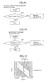
- FIG. 9 shows the abnormal region detected by the anomalous current detector 105.
- the horizontal axis represents the first torque signal Tmain
- the vertical axis represents the motor drive current Io.
- the anomalous current detector 105 detects an abnormality of electric power steering control, that is, determines that the main microcomputer 1-1 is in an abnormal state, when the motor drive current Io exceeds a given value with no or almost zero steering force (torque) applied to the steering wheel 7. Specifically, the anomalous current detector 105 detects an abnormality when the first torque signal Tmain is within the range of Tmmin3 and Tmmax3 with almost zero torque applied and when the motor drive current Io is equal to or greater than Iomax. The abnormal region detected by the anomalous current detector 105 is shown by the hatched region Ic of FIG. 9 .
- the hatched region Ic of FIG. 9 is also shown in FIG. 6 where the horizontal axis represents not the first torque signal Tmain but the absolute value of the steering force ⁇ (torque) applied to the steering wheel 7.
- the anomalous current detector 105 could be regarded as a special form of the anomalous torque-current correlation detector 104, but the former judges even smaller motor drive current Io to be abnormal than the latter does, as illustrated in FIG. 6 . This is because the correlation between the steering force ⁇ (torque) and the motor drive current Io varies depending on vehicle speed and other factors and also because the anomalous torque-current correlation detector 104 has to take this change into account to judge a wider range normal.
- the excessive torque detector 102 and the anomalous current detector 105 could be said to have higher abnormality detection capabilities than the anomalous torque-current correlation detector 104 does.
- the anomalous current detector 105 detects an abnormality (the region Ic) when the drive current Io exceeds a given value with no or almost zero steering force (torque) applied to the steering wheel 7, provided that the operation of the torque sensor 2 is normal. This prevents an abnormality of the torque sensor 2 from stopping the operation of the motor 6. The conditions with which to determine the operation of the torque sensor 2 is normal will later be discussed with reference to FIG. 10 .
- Methods for stopping the motor 6 include 1) masking the motor drive signals 3 with the use of AND gates 11, 2) disconnecting a main relay 12 to stop power supply to the three-phase inverter 5, and 3) disconnecting phase output relays 13 to stop current supply to the motor 6. While the power steering system of FIG. 1 includes the AND gates 11, the main relay 12, and the phase output relays 13, only one component of the three may be used to stop current supply to the motor 6. In that case, the power steering system includes the main relay 12 or the phase output relays 13. Alternatively, current supply to the motor 6 may be stopped by using two components of the three; in that case, the power steering system includes the main relay 12 and the phase output relays 13.
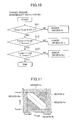
- FIG. 10 is a flowchart of the detection performed by the torque sensor abnormality detector 101.
- FIG. 11 is a graph illustrating the abnormal regions detected by the torque sensor abnormality detector 101 in which the abnormal regions detected by the detectors 102, 104, and 105 of the external device 1-2 are also shown.
- the horizontal axis represents the first torque signal Tmain while the vertical axis represents the second torque signal Tsub.
- the torque sensor abnormality detector 101 inside the main microcomputer 1-1 receives the first torque signal Tmain and the second torque signal Tsub.
- the torque sensor abnormality detector 101 judges the signals Tmain and Tsub normal if the signals are each within an acceptable voltage range; if not, the detector 101 judges them abnormal.
- the use of the torque sensor abnormality detector 101 allows detection of abnormalities attributable to short-circuiting of the wires for the first and second torque signals Tmain and Tsub to the ground or power supply. Also, when either one of the first torque signal Tmain and the second torque signal Tsub is out of its acceptable voltage range, the torque sensor abnormality detector 101 judges that signal to be abnormal and continues control using the other normal signal.
- the torque sensor abnormality detector 101 detects an abnormality of the torque sensor 2 if the following condition is met.
- Step S11 of FIG. 10 the torque sensor abnormality detector 101 judges the torque sensor 2 to be normal when the difference between (Tmain + Tsub) and 5.0 V is lower than an error ⁇ (that is,
- the torque sensor abnormality detector 101 detects an abnormality of the torque sensor 2 (as illustrated by the regions II of FIG. 11 ).
- the main microcomputer 1-1 When an abnormality is detected with the use of the regions II (that is, when the operation of the torque sensor 2 is abnormal), the main microcomputer 1-1 gradually reduces the output torque of the motor 6 or continues control with the use of the other torque sensor unit which has been judged not abnormal.
- the torque sensor abnormality detector 101 detects an abnormality (the regions IIm of FIG. 11 ) when the first torque signal Tmain deviates from the range between two threshold values: Tmmax2 and Tmmin2. In Step S13, the torque sensor abnormality detector 101 also detects an abnormality (the regions IIs of FIG. 11 ) when the second torque signal Tsub is out of the range of Tsmax2 to Tsmin2.
- the threshold values Tmmax2 and Tsmax2 used to detect excessive torque can be determined based on steering forces at the time of normal operation and on the steering force required to generate the largest rack propulsion.
- the largest rack propulsion is 10,000 N and the pinion gear used to move the rack has a pitch-circle diameter of 5 cm (a pitch-circle radius of 2.5 cm).
- the torque at the time of the largest rack propulsion is 250 Nm
- the steering force (torque) applied to the steering wheel 7 is 25 Nm, provided that the motor 6 increases the steering force (torque) applied to the steering wheel 7 tenfold. Therefore, when the steering force (torque) applied to the steering wheel 7 exceeds 25 Nm, it can be determined that something abnormal has happened.
- FIG. 12 lists the detections performed by the torque sensor abnormality detector 101 and by the components of the external device 1-2 of the electric power steering controller of Embodiment 1.
- FIG. 12 summarizes which abnormality detector detects which abnormality (an abnormality of the main microcomputer 1-1 or of the torque sensor 2).
- Described first is a case where the driver is controlling or holding the steering wheel 7 when the operation of the main microcomputer 1-1 has become abnormal. If the abnormality of the main microcomputer 1-1 is accompanied by steering lock, the driver would apply a large steering force to the steering wheel 7 so as to control the vehicle. As a result, the excessive torque detector 102 will detect the abnormality (the region Ia of FIG. 6 ). The anomalous torque-current detector 104 also detects the abnormality (the regions Ib of FIG. 6 ) because drive current is applied to the motor 6, irrespective of the steering force.
- the excessive torque detector 102 will detect the abnormality (the region Ia of FIG. 6 ).
- Self-steering refers to steering movements unintended by the driver; it happens regardless of whether the driver is holding the steering wheel 7 or not.
- the anomalous torque-current detector 104 also detects the abnormality (the regions Ib of FIG. 6 ) because drive current is applied to the motor 6, irrespective of the steering force.
- the failure mode that will take effect in this case is self-steering resulting from the abnormality of the main microcomputer 1-1. Because, in this case, drive current is applied to the motor 6 despite application of no steering force, the anomalous current detector 105 detects the abnormality (the region Ic of FIG. 6 ).
- the external device 1-2 When an abnormality of the main microcomputer 1-1 has been detected by either of the detectors 102, 104 and 105 as above, the external device 1-2 outputs a signal to stop the operation of the motor 6.
- the torque sensor abnormality detector 101 inside the main microcomputer 1-1 detects the abnormality. This is followed by gradual reduction of the output torque by the main microcomputer 1-1 or control continuation with the use of the other torque sensor unit which has been judged not abnormal.
- the operation of the motor 6 is stopped.
- the torque sensor abnormality detector 101 detects an abnormality of the torque sensor 2
- the external device 1-2 stops the operation of the excessive torque detector 102, the anomalous torque-current correlation detector 104, and the anomalous current detector 105 using an abnormality signal transmitted from the torque sensor abnormality detector 101.
- the abnormality detection by the torque sensor abnormality detector 101 is prioritized over the abnormality detections by the excessive torque detector 102, the anomalous torque-current correlation detector 104, and the anomalous current detector 105.
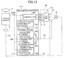
- FIG. 13 is an alternative configuration of the electric power steering system of FIG. 1 with the electric power steering controller of Embodiment 1.
- FIG. 13 is a block diagram illustrating that system.
- the same reference numerals as those used in FIG. 1 denote identical components.
- the motor drive current Io is detected by the current sensor SA, which is attached to the wiring used to supply the voltage VB from a battery or the like to the three-phase inverter 5.
- current sensors SP are attached to the power supply wires of the three-phase inverter 5 which are connected to the phase wires of the motor 6.
- the current sensors SP are designed to detect phase currents.
- the anomalous torque-current correlation detector 104 and the anomalous current detector 105 each calculate the total current using the phase currents detected by the current sensors SP and the magnetic pole position of the motor 6. Thereafter, the detectors 104 and 105 perform abnormality detection based on the total current and on the first and second torque signals Tman and Tsub.
- an electric power steering system is designed to detect an abnormality of its main microcomputer and unable to detect an abnormality of its torque sensor. As a result, such a system may misjudge an abnormality of the torque sensor as an abnormality of the main microcomputer. Because a power steering system requires different operations for torque-sensor abnormalities and main-microcomputer abnormalities, it has to distinguish between them.
- Embodiment 1 is thus designed such that the torque sensor abnormality detector 101 of the main microcomputer 1-1 detects an abnormality of the redundant torque sensor 2 based on the output of the torque sensor 2.
- the main microcomputer 1-1 performs gradual torque reduction.
- the abnormality detection by the torque sensor 2 is prioritized over the abnormality detection by the external device 1-2.
- the external device 1-2 does not regard an abnormality of the torque sensor 2 as an excessive steering force. Accordingly, the main microcomputer 1-1 can perform gradual torque reduction without stopping the operation of the motor 6.
- the external device 1-2 detects abnormalities of the main microcomputer 1-1.
- the excessive torque detector 102 regards this as an abnormality of electric power steering control, that is, an abnormality of the main microcomputer 1-1 that exercises the control.
- the motor 6 is caused to stop. It is therefore possible to detect abnormalities of the torque sensor 2 and abnormalities of the main microcomputer 1-1 in a distinguishable manner, thereby achieving abnormality-based system control.
- a conventional power steering system is based on the assumption that the driver is always controlling or holding the steering wheel, mere monitoring of excessive torque by the system does not make it possible to detect self-steering when the driver is not holding the steering wheel or when the driver releases his hands from the steering wheel.
- Embodiment 1 is also designed such that the anomalous current detector 105 monitors the steering force and the current that flows through the motor 6.
- the anomalous current detector 105 regards this as abnormality of electric power steering control, that is, an abnormality of the main microcomputer 1-1 that exercises the control, thereby stopping the operation of the motor 6. This allows detection of self-steering even when the driver is not controlling or holding the steering wheel 7.
- the anomalous torque-current correlation detector 104 monitors the correlation between the steering force and the current that flows through the motor 6. When the correlation is disrupted with the steering wheel 7 not being controlled or held by the driver, the anomalous torque-current correlation detector 104 can detect steering lock or self-steering and regards this as an abnormality of electric power steering control, that is, an abnormality of the main microcomputer 1-1 that exercises the control, thereby stopping the operation of the motor 6.
- Embodiment 1 allows appropriate system control even when the operation of the torque sensor 2 is abnormal.
- Embodiment 1 further allows detection of self-steering when the driver is not holding the steering wheel 7 or when the driver releases his hands from the steering wheel 7.
- Embodiment 1 allows detection of steering lock or self-steering when the driver is controlling or holding the steering wheel 7.
- FIGS. 14 through 17 Described next with reference to FIGS. 14 through 17 are the configuration and operation of an electric power steering controller according to Embodiment 2 of the invention.
- FIG. 14 is a block diagram illustrating that system.
- the same reference numerals as those used in FIG. 1 denote identical components.
- the first and second torque signals Tmain and Tsub are input to the main microcomputer 1-1.
- the external device 1-2 receives only the first torque signal Tmain.
- the main microcomputer 1-1 includes the controller 100 and a torque sensor abnormality detector 101A.
- the controller 100 outputs motor drive signals 3 to the three-phase inverter 5 based on the first torque signal Tmain or the second torque signal Tsub and on a magnetic pole signal detected by a magnetic pole sensor installed in the motor 6.
- the torque sensor abnormality detector 101A obtains the difference between the first and second torque signals Tmain and Tsub, thereby detecting an abnormality of the torque sensor 2.
- the external device 1-2 includes only the excessive torque detector 102.
- the excessive torque detector 102 receives the first torque signal Tmain.
- the excessive torque detector 102 detects an abnormality of electric power steering control, that is, an abnormality of the main microcomputer 1-1, thereby stopping the operation of the motor 6.
- FIG. 14 illustrates the use of the first torque signal Tmain for the detection of positively or negatively excessive torque
- the excessive torque detector 102 may instead use the second torque signal Tsub.
- the second torque signal Tsub is lower than a given threshold value (i.e., negatively excessive steering force or torque) or greater than a given threshold value (i.e., positively excessive steering force or torque)
- the excessive torque detector 102 detects an abnormality of electric power steering control, that is, an abnormality of the main microcomputer 1-1, thereby stopping the operation of the motor 6.
- FIG. 15 is a flowchart illustrating the operation of the torque sensor abnormality detector 101A of Embodiment 2.
- Step S11 of FIG. 15 the torque sensor abnormality detector 101A judges the torque sensor 2 to be normal when the difference between (Tmain + Tsub) and 5.0 V is lower than an error ⁇ (that is,
- the torque sensor abnormality detector 101A detects an abnormality of the torque sensor 2 (as illustrated by the regions II of FIG. 17 ).
- FIG. 16 is a flowchart illustrating the operation of the excessive torque detector 102 of Embodiment 2.
- Step S21 the excessive torque detector 102 judges the main microcomputer 1-1 to be normal if the first torque signal Tmain is within the range of Tmmax2 to Tmmin2 (i.e., Tmmin2 ⁇ Tmain ⁇ Tmmax2); if not, the detector 102 judges the main microcomputer 1-1 to be abnormal (the regions Ia of FIG. 17 ).
- the threshold values used to detect excessive torque can be determined based on steering forces at the time of normal operation and on the steering force required to generate the largest rack propulsion.
- the largest rack propulsion is 10,000 N and the pinion gear used to move the rack has a pitch-circle diameter of 5 cm (a pitch-circle radius of 2.5 cm).
- the torque at the time of the largest rack propulsion is 250 Nm
- the steering force (torque) applied to the steering wheel 7 is 25 Nm, provided that the motor 6 increases the steering force (torque) applied to the steering wheel 7 tenfold. Therefore, when the steering force (torque) applied to the steering wheel exceeds 25 Nm, it can be determined that something abnormal has happened.
- FIG. 17 is a graph illustrating the abnormal regions.
- the horizontal axis represents the first torque signal Tmain while the vertical axis represents the second torque signal Tsub.
- An abnormality is detected (the regions Ia) when the first torque signal Tmain is out of the range of Tmmax2 to Tmmin2.
- an abnormality is detected (the regions II) when the difference between (Tmain + Tsub) and 5.0 V is equal to or greater than the error ⁇ .
- Embodiment 2 allows detection of abnormalities of the torque sensor 2 and abnormalities of the main microcomputer 1-1 in a distinguishable manner; thus, appropriate system control is possible even when the operation of the torque sensor 2 is abnormal.
- FIG. 18 is a block diagram illustrating the configuration of an electric power steering system with the steering controller of Embodiment 3.
- the same reference numerals as those used in FIG. 14 denote identical components.
- FIG. 19 is a graph illustrating the abnormal regions detected by the power steering controller of Embodiment 3.
- the first and second torque signals Tmain and Tsub are input to the main microcomputer 1-1.
- the external device 1-2 receives only the first torque signal Tmain.
- the main microcomputer 1-1 includes the controller 100 and the torque sensor abnormality detector 101A.
- the controller 100 outputs motor drive signals 3 to the three-phase inverter 5 based on the first torque signal Tmain or the second torque signal Tsub and on a magnetic pole signal detected by a magnetic pole sensor installed in the motor 6.
- the torque sensor abnormality detector 101A is the same as that illustrated in FIG. 14 ; it obtains the difference between the first and second torque signals Tmain and Tsub, thereby detecting an abnormality of the torque sensor 2.
- the external device 1-2 includes only an excessive torque detector 102A.
- the excessive torque detector 102A receives the first torque signal Tmain and a vehicle speed signal 14. When the first torque signal Tmain is lower than a given threshold value (i.e., negatively excessive steering force or torque) or greater than a given threshold value (i.e., positively excessive steering force or torque), the excessive torque detector 102A detects an abnormality of electric power steering control, that is, an abnormality of the main microcomputer 1-1, thereby stopping the operation of the motor 6.
- a given threshold value i.e., negatively excessive steering force or torque
- a given threshold value i.e., positively excessive steering force or torque
- the excessive torque detector 102A can vary the threshold values Tmmax2 and Tmmin2 based on the vehicle speed signal 14. As illustrated in FIG. 19(A) , the range of Tmmax2 to Tmmin2 is widened when the vehicle speed is low, so that a larger steering force can be judged normal. Conversely, when the vehicle speed is high, the range of Tmmax2 to Tmmin2 is narrowed as illustrated in FIG. 19(B) , so that a smaller steering force can be judged abnormal.
- Embodiment 3 allows detection of abnormalities of the torque sensor 2 and abnormalities of the main microcomputer 1-1 in a distinguishable manner; thus, appropriate system control is possible even when the operation of the torque sensor 2 is abnormal.
- the range with which to detect excessive torque can be varied based on the vehicle speed. At low speed when a large steering force is required, the driver is allowed to apply a large steering force. At high speed when a large steering force is not necessary, abnormalities can be detected more reliably.
- FIG. 20 is a block diagram illustrating the configuration of an electric power steering system with the steering controller of Embodiment 4.
- the same reference numerals as those used in FIG. 1 denote identical components.
- FIG. 21 is a graph illustrating the abnormal regions detected by the power steering controller of Embodiment 4.
- the first and second torque signals Tmain and Tsub are input to the main microcomputer 1-1.
- the external device 1-2 receives only the first torque signal Tmain.
- the main microcomputer 1-1 includes the controller 100 and the torque sensor abnormality detector 101.
- the controller 100 outputs motor drive signals 3 to the three-phase inverter 5 based on the first torque signal Tmain or the second torque signal Tsub and on a magnetic pole signal detected by a magnetic pole sensor installed in the motor 6.
- the torque sensor abnormality detector 101 obtains the difference between the first and second torque signals Tmain and Tsub, thereby detecting an abnormality of the torque sensor 2. As in FIG. 10 , the torque sensor abnormality detector 101 detects an abnormality when the first and second torque signals Tmain and Tsub are in any of the abnormal regions II, IIm, and IIs of FIG. 21 . This allows detection of abnormalities attributable to short-circuiting of the wires for the first and second torque signals Tmain and Tsub to the ground or power supply. Also, when either of the torque signals Tmain and Tsub is out of a given voltage range, the torque sensor abnormality detector 101 judges that signal to be abnormal, thus allowing control continuation with the use of the other torque signal.
- the external device 1-2 includes only the excessive torque detector 102.
- the excessive torque detector 102 receives only the first torque signal Tmain.
- the first torque signal Tmain is lower than a given threshold value (i.e., negatively excessive steering force or torque) or greater than a given threshold value (i.e., positively excessive steering force or torque)
- the excessive torque detector 102 detects an abnormality of electric power steering control, that is, an abnormality of the main microcomputer 1-1, thereby stopping the operation of the motor 6.
- the external device 1-2 receives only the first torque signal Tmain.
- a first torque signal Tmain equivalent to a large steering force is input to the external device 1-2, no judgment can be made as to whether that is due to an abnormality of the torque sensor 2 or to the driver's steering. Accordingly, when the first torque signal Tmain is out of a given voltage range, the excessive torque detector 102 of the external device 1-2 regards this as the occurrence of an excessive steering force, and control continuation with the use of the second torque signal Tsub becomes impossible.
- FIG. 20 illustrates the use of the first torque signal Tmain for the detection of positively or negatively excessive torque
- the excessive torque detector 102 may instead use the second torque signal Tsub.
- the second torque signal Tsub is lower than a given threshold value (i.e., negatively excessive steering force or torque) or greater than a given threshold value (i.e., positively excessive steering force or torque)
- the excessive torque detector 102 detects an abnormality of electric power steering control, that is, an abnormality of the main microcomputer 1-1, thereby stopping the operation of the motor 6.
- the horizontal axis represents the first torque signal Tmain while the vertical axis represents the second torque signal Tsub.
- the excessive torque detector 102 detects an abnormality (the regions Ia) when the first torque signal Tmain is out of the range of Tmmax2 to Tmmin2.
- the torque sensor abnormality detector 101 detects an abnormality (the regions II) when the difference between (Tmain + Tsub) and 5.0 V is equal to or greater than the error ⁇ .
- the torque sensor abnormality detector 101 also detects an abnormality (the regions IIm) when the first torque signal Tmain is out of the voltage range of Tmmax2 to Tmmin2.
- the torque sensor abnormality detector 101 detects an abnormality (the regions IIs) when the second torque signal Tsub is out of the range of Tsmax2 to Tsmin2.
- Embodiment 4 allows detection of abnormalities of the torque sensor 2 and abnormalities of the main microcomputer 1-1 in a distinguishable manner; thus, appropriate system control is possible even when the operation of the torque sensor 2 is abnormal.
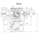
- FIG. 22 is a block diagram illustrating the configuration of an electric power steering system with the steering controller of Embodiment 5.
- the same reference numerals as those used in FIG. 1 denote identical components.
- FIG. 23 is a flowchart illustrating the operation of an excessive torque detector 102B used for the power steering controller of Embodiment 5.
- FIG. 24 is a graph illustrating the abnormal regions detected by the power steering controller of Embodiment 5.
- the first and second torque signals Tmain and Tsub are input to the main microcomputer 1-1 and also to the external device 1-2.
- the main microcomputer 1-1 includes the controller 100 and the torque sensor abnormality detector 101.
- the controller 100 outputs motor drive signals 3 to the three-phase inverter 5 based on the first torque signal Tmain or the second torque signal Tsub and on a magnetic pole signal detected by a magnetic pole sensor installed in the motor 6.
- the torque sensor abnormality detector 101 obtains the difference between the first and second torque signals Tmain and Tsub, thereby detecting an abnormality of the torque sensor 2. As in FIG. 10 , the torque sensor abnormality detector 101 detects an abnormality when the first and second torque signals Tmain and Tsub are in any of the abnormal regions II, IIm, and IIs of FIG. 24 . This allows detection of abnormalities attributable to short-circuiting of the wires for the first and second torque signals Tmain and Tsub to the ground or power supply. Also, when either of the torque signals Tmain and Tsub is out of a given voltage range, the torque sensor abnormality detector 101 judges that signal to be abnormal, thus allowing control continuation with the use of the other torque signal.
- the external device 1-2 includes only the excessive torque detector 102B.
- the excessive torque detector 102B receives both of the first and second torque signals Tmain and Tsub for abnormality detection.
- the excessive torque detector 102B detects an abnormality of the main microcomputer 1-1 only when an excessive steering force (torque) is applied with the operation of the torque sensor 2 being normal; the abnormality detection causes the motor 6 to stop.
- Embodiment 5 when the operation of the torque sensor 2 is abnormal, the excessive torque detector 102B makes no judgment whether to stop the motor 6 or not; thus, the main microcomputer 1-1 can continue the operation of the motor 6. Further, when either of the torque signals Tmain and Tsub is out of a given voltage range, the main microcomputer 1-1 judges that signal to be abnormal, thus allowing control continuation with the use of the other torque signal.
- the excessive torque detector 102B makes no judgment whether to stop the operation of the motor 6 or not, provided that the main microcomputer 1-1 has already started any of the operations of FIG. 12 for the abnormality of the torque sensor 2 within a given period of time.
- Embodiment 5 makes it possible to detect abnormalities of the main microcomputer 1-1 even when the operation of the torque sensor 2 is abnormal and subsequently stop the operation of the motor 6.
- the excessive torque detector 102B detects an abnormality (the regions Ia) in Step S21' if the equation
- Step S23 the excessive torque detector 102B detects an abnormality (the regions Ia) if the equation
- the horizontal axis represents the first torque signal Tmain while the vertical axis represents the second torque signal Tsub.
- the excessive torque detector 102B detects an abnormality (the regions Ia) when the first torque signal Tmain is out of the range of Tmmax2 to Tmmin2.
- the torque sensor abnormality detector 101 detects an abnormality (the regions II) when the difference between (Tmain + Tsub) and 5.0 V is equal to or greater than the error ⁇ .
- the torque sensor abnormality detector 101 also detects an abnormality (the regions IIm) when the first torque signal Tmain is out of the voltage range of Tmmax2 to Tmmin2.
- the torque sensor abnormality detector 101 detects an abnormality (the regions IIs) when the second torque signal Tsub is out of the range of Tsmax2 to Tsmin2.
- Embodiment 5 allows detection of abnormalities of the torque sensor 2 and abnormalities of the main microcomputer 1-1 in a distinguishable manner; thus, appropriate system control is possible even when the operation of the torque sensor 2 is abnormal.
- FIG. 25 is a block diagram illustrating the configuration of an electric power steering system with the steering controller of Embodiment 6.
- the same reference numerals as those used in FIG. 18 denote identical components.
- the first and second torque signals Tmain and Tsub are input to the main microcomputer 1-1 and also to the external device 1-2.
- the main microcomputer 1-1 includes the controller 100 and the torque sensor abnormality detector 101.
- the controller 100 outputs motor drive signals 3 to the three-phase inverter 5 based on the first torque signal Tmain or the second torque signal Tsub and on a magnetic pole signal detected by a magnetic pole sensor installed in the motor 6.
- the torque sensor abnormality detector 101 obtains the difference between the first and second torque signals Tmain and Tsub, thereby detecting an abnormality of the torque sensor 2. As in FIG. 10 , the torque sensor abnormality detector 101 detects an abnormality when the first and second torque signals Tmain and Tsub are in any of the abnormal regions II, IIm, and IIs of FIG. 24 . This allows detection of abnormalities attributable to short-circuiting of the wires for the first and second torque signals Tmain and Tsub to the ground or power supply. Also, when either of the torque signals Tmain and Tsub is out of a given voltage range, the torque sensor abnormality detector 101 judges that signal to be abnormal, thus allowing control continuation with the use of the other torque signal.
- the external device 1-2 includes only an excessive torque detector 102C.
- the excessive torque detector 102C receives the first and second torque signals Tmain and Tsub and the vehicle speed signal 14. Similar to the excessive torque detector 102B of FIG. 22 , the excessive torque detector 102C inspects both of the first and second torque signals Tmain and Tsub for abnormality detection.
- the excessive torque detector 102C detects an abnormality of the main microcomputer 1-1 only when an excessive steering force (torque) is applied with the operation of the torque sensor 2 being normal; the abnormality detection causes the motor 6 to stop.
- the excessive torque detector 102C can vary the threshold values Tmmax2 and Tmmin2 based on the vehicle speed signal 14. As illustrated in FIG. 19(A) , the range of Tmmax2 to Tmmin2 is widened when the vehicle speed is low, so that a larger steering force can be judged normal. Conversely, when the vehicle speed is high, the range of Tmmax2 to Tmmin2 is narrowed as illustrated in FIG. 19(B) , so that a smaller steering force can be judged abnormal.
- Embodiment 6 allows detection of abnormalities of the torque sensor 2 and abnormalities of the main microcomputer 1-1 in a distinguishable manner; thus, appropriate system control is possible even when the operation of the torque sensor 2 is abnormal.
- the range with which to detect excessive torque can be varied based on the vehicle speed. At low speed when a large steering force is required, the driver is allowed to apply a large steering force. At high speed when a large steering force is not necessary, abnormalities can be detected more reliably.
- FIG. 26 is a block diagram illustrating the configuration of an electric power steering system with the steering controller of Embodiment 7.
- the same reference numerals as those used in FIG. 1 denote identical components.
- Embodiment 7 is designed such that the external device 1-2 stops current supply to the motor 6 after a possible abnormal state has lasted for a given amount of time.
- the external device 1-2 of Embodiment 7 includes the following components: an OR circuit OR1 for performing an OR operation on the outputs from the excessive torque detector 102 and from the anomalous current detector 105; a timer circuit T1, connected to the output of the OR circuit OR1, for measuring a fixed time t01; a timer circuit T2, connected to the output of the anomalous torque-current correlation detector 104, for measuring a fixed time t02; and a NOR circuit NR1, connected to the outputs of the timer circuits T1 and T2, for performing a NOR operation on the outputs from the timer circuits T1 and T2.
- the above first condition 1) is based on the consideration of a possible case where the driver may release his hands from the steering wheel 7 after applying a steering force with the intention of stopping self-steering.
- the reason the two timer circuits T1 and T2 are provided is that the abnormality detection by the excessive torque detector 102 or by the anomalous current detector 105 and the abnormality detection by the anomalous torque-current correlation detector 104 are different events.
- the fixed time t01 may be the same in length as the fixed time t02.
- the time t01 can be set based on the magnitude of the steering force (torque) detected by the excessive torque detector 102. For instance, the time t01 can be several seconds when the steering force is 10 Nm, which is larger than a normal steering force of 2-3 Nm. When the steering force exceeds 25 Nm, which is equivalent to the steering force (torque) required to generate the largest rack propulsion, the time t01 can be set to several milliseconds by taking into consideration the time required for rack-end protection.
- Embodiment 7 allows detection of abnormalities of the torque sensor 2 and abnormalities of the main microcomputer 1-1 in a distinguishable manner; thus, appropriate system control is possible even when the operation of the torque sensor 2 is abnormal.
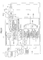
- FIG. 27 is a block diagram illustrating the configuration of an electric power steering system with the steering controller of Embodiment 8.
- the same reference numerals as those used in FIG. 1 denote identical components.
- Embodiment 8 is designed such that the external device 1-2 stops current supply to the motor 6 if the abnormality detection by either of the excessive torque detector 102, the anomalous current detector 105, and the anomalous torque-current correlation detector 104 has lasted for more than the fixed time t01. This condition is based on the consideration of a possible case where the driver's release of his hands from the steering wheel 7 may result in the application of torque to the torque sensor 2 due to the inertia of the steering wheel 7.
- the external device 1-2 includes the following components: a NOR circuit NR2 for performing a NOR operation on the outputs from the excessive torque detector 102, the anomalous current detector 105, and the anomalous torque-current correlation detector 104; and a timer circuit T3, connected to the output of the NOR circuit NR2, for measuring the fixed time t01.
- Embodiment 8 allows detection of abnormalities of the torque sensor 2 and abnormalities of the main microcomputer 1-1 in a distinguishable manner; thus, appropriate system control is possible even when the operation of the torque sensor 2 is abnormal.
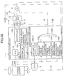
- FIG. 28 is a block diagram illustrating the configuration of an electric power steering system with the steering controller of Embodiment 9.
- the same reference numerals as those used in FIG. 1 denote identical components.
- FIG. 29 is a timing chart illustrating the operation of the power steering controller of Embodiment 9.
- the external device 1-2 of Embodiment 9 includes a rack-end protection detector 106 in addition to the components of the external device 1-2 of FIG. 1 . Even if the excessive torque detector 102 has detected an abnormality resulting from a large steering force (torque), the rack-end protection detector 106 prevents discontinuation of current supply to the motor 6, provided that the rack-end protection detector 106 has detected a rack-end protection operation by the main microcomputer 1-1 (decrease in Io by more than Ioth) within a given time frame tth.
- the rack-end protection detector 106 prevents discontinuation of current supply to the motor 6, provided that the rack-end protection detector 106 has detected a rack-end protection operation by the main microcomputer 1-1 (decrease in Io by more than Ioth) within a given time frame tth.
- the external device 1-2 of Embodiment 9 further includes the following components: an AND circuit AN1 for performing an AND operation on the inverted output from the rack-end protection detector 106 and the output from the excessive torque detector 102; a timer circuit T4, connected to the output of the AND circuit AN1, for measuring the time tth; an AND circuit AN2 for performing an AND operation on the inverted output from the rack-end protection detector 106 and the output from the anomalous torque-current correlation detector 104; and a NOR circuit NR3 for performing an NOR operation on the outputs from the timer circuit T4, the anomalous current detector 105, and the AND circuit AN2.
- FIG. 29 is a timing chart illustrating the operation of the power steering controller of Embodiment 9, where ' ⁇ ' denotes the steering force, and 'Io' denotes the motor drive current.
- the reference character 'A' denotes the inverted output from the rack-end protection detector 106, 'B' the output from the excessive torque detector 102, 'C' the output from the anomalous torque-current correlation detector 104, 'D' the output from the AND circuit AN1, 'E' the output from the AND circuit AN2, 'F' the output from the timer circuit T4, and 'G' the output from the NOR circuit NOR3.
- the solid lines represent signals obtained when a rack-end protection operation is performed whereas the dashed lines represent signals obtained when a rack-end protection operation is not performed.
- Rack-end protection is performed by the controller 100.
- the controller 100 monitors motor drive signals 3. When the motor drive current Io keeps exceeding a given value for a given amount of time, the controller 100 regards this as the contact of the pinion gear with either end of the rack (hereinafter referred to simply as 'rack-end contact') and then performs rack-end protection by reducing the motor drive current Io by more than Ioth.
- the excessive torque detector 102 regards this as abnormal and makes its output B high.
- the rack-end protection detector 106 detects the rack-end protection performed by the controller 100, its output A becomes high.
- the output D of the AND circuit AN1 becomes also high. If the rack-end protection is detected within the time frame tth, the output F of the timer circuit T4 does not become high, and the output G of the NOR circuit NOR3 stays high, thereby not stopping the operation of the motor 6.
- the anomalous torque-current correlation detector 104 regards this as abnormal, making its output C high. In this case, too, the output A becomes high. Thus, the output E of the AND circuit AN2 stays low, and the output G of the NOR circuit NOR3 stays high, thereby not stopping the operation of the motor 6.
- the rack-end protection detector 106 does not detect rack-end protection. Thus, even after the time frame tth has passed, the output D of the AND circuit AN1 remains high as illustrated by the dashed line. Also, the output F of the timer circuit T4 becomes high, and the output G of the NOR circuit NOR3 becomes low, thereby stopping the operation of the motor 6.
- a power steering system does not distinguish between an excessive steering force exerted by the driver and a transient impact in the event of rack-end contact.
- a transient impact is caused at the rack end. If the system misjudges this impact as an excessive steering force exerted by the driver, the system brings its power steering control to an emergency stop even when the system operates properly. Subsequently, drivability will be affected for lack of steering assistance.
- the external device 1-2 of Embodiment 9 includes the rack-end protection detector 106 so as not to regard a steering force larger than a given value as an excessive steering force in the event of rack-end contact.
- the rack-end protection detector 106 regards a decrease in the motor drive current Io within a given time frame as the rack-end protection performed by the main microcomputer 1-1.
- the rack-end protection detector 106 judges whether or not the operation of the main microcomputer 1-1 is abnormal by examining whether or not the main microcomputer 1-1 is performing a rack-end protection operation.
- the larger steering force is regarded as an abnormality of electric power steering control, that is, an abnormality of the main microcomputer 1-1. Even if the larger steering force has actually resulted from rack-end contact, the larger steering force can be regarded as an abnormality of the main microcomputer 1-1 when the main microcomputer 1-1 is not performing a rack-end protection operation.
- Embodiment 9 allows detection of abnormalities of the torque sensor 2 and abnormalities of the main microcomputer 1-1 in a distinguishable manner; thus, appropriate system control is possible even when the operation of the torque sensor 2 is abnormal.
- Embodiment 9 makes it possible to distinguish between an excessive steering force intended by the driver and an excessive steering force resulting from a rack-end impact.
- a rack-end protection operation can be performed.
- FIG. 30 is a block diagram illustrating the configuration of an electric power steering system with the steering controller of Embodiment 10.
- the same reference numerals as those used in FIG. 1 denote identical components.
- the power steering controller of Embodiment 10 includes an external device 1-2A.
- the external device 1-2A is a sub-microcomputer for monitoring the main microcomputer 1-1.
- the main microcomputer 1-1 and the external device 1-2A include an arithmetic calculator 103-1 and an arithmetic calculator 103-2, respectively.
- the arithmetic calculator 103-1 instructs the arithmetic calculator 103-2 to perform a simple arithmetic calculation and compares the calculation result of the arithmetic calculator 103-2 against its own calculation result, thereby making sure the external device 1-2A is working properly.
- the arithmetic calculator 103-2 also does the same to the arithmetic calculator 103-1.
- the functions of the arithmetic calculators 103-1 and 103-2 are cross-checked on an as-needed basis.
- AD converter 9 installed within the main microcomputer 1-1. This is achieved by the arithmetic calculator 103-2 instructing a DA converter 8 to output an analog signal to the AD converter 9 and then the arithmetic calculator 103-1 checking a signal from the AD converter 9.
- Embodiment 10 allows detection of abnormalities of the torque sensor 2 and abnormalities of the main microcomputer 1-1 in a distinguishable manner; thus, appropriate system control is possible even when the operation of the torque sensor 2 is abnormal.
- FIG. 31 is a block diagram illustrating the configuration of an electric power steering system with the steering controller of Embodiment 11.
- the same reference numerals as those used in FIG. 1 denote identical components.
- the external device (sub-microcomputer) 1-2A includes a CAN (Controller Area Network) interface 114.
- the CAN interface receives a vehicle speed signal 14 and transmits the signal 14 to the main microcomputer 1-1. It is preferred that the transmission of the signal 14 to the main microcomputer 1-1 be through a simple circuit interface such as an SPI (Serial Port Interface) and the like.
- Embodiment 11 allows detection of abnormalities of the torque sensor 2 and abnormalities of the main microcomputer 1-1 in a distinguishable manner; thus, appropriate system control is possible even when the operation of the torque sensor 2 is abnormal.
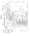
- FIG. 32 is a block diagram illustrating the configuration of an electric power steering system with the steering controller of Embodiment 12.
- the same reference numerals as those used in FIG. 1 denote identical components.
- the power steering controller of Embodiment 12 includes an external device 1-2B.
- the external device 1-2B is implemented by a power IC and includes the following components: a regulator 106 for supplying power to the main microcomputer 1-1; and a watchdog timer 107 for transmitting a RESET signal to the main microcomputer 1-1 when the power is turned on or when the main microcomputer 1-1 has not transmitted an "I'm alive" signal for a given amount of time.
- Embodiment 12 allows detection of abnormalities of the torque sensor 2 and abnormalities of the main microcomputer 1-1 in a distinguishable manner; thus, appropriate system control is possible even when the operation of the torque sensor 2 is abnormal.
- the above-described embodiments of the invention allow detection of abnormalities of a main microcomputer without any misdetection in the event of torque-sensor abnormalities or rack-end contact and also without requiring any special components for the main microcomputer. Moreover, the invention makes it possible to detect not only abnormalities of the main microcomputer but abnormalities of an inverter predriver and an inverter and bugs of control software as well.
Landscapes
- Engineering & Computer Science (AREA)
- Chemical & Material Sciences (AREA)
- Combustion & Propulsion (AREA)
- Transportation (AREA)
- Mechanical Engineering (AREA)
- Power Steering Mechanism (AREA)
- Steering Control In Accordance With Driving Conditions (AREA)
- Control Of Electric Motors In General (AREA)
Applications Claiming Priority (1)
| Application Number | Priority Date | Filing Date | Title |
|---|---|---|---|
| JP2010050993A JP5086385B2 (ja) | 2010-03-08 | 2010-03-08 | 電動パワーステアリング制御装置 |
Publications (3)
| Publication Number | Publication Date |
|---|---|
| EP2364897A2 true EP2364897A2 (fr) | 2011-09-14 |
| EP2364897A3 EP2364897A3 (fr) | 2012-08-15 |
| EP2364897B1 EP2364897B1 (fr) | 2016-09-21 |
Family
ID=44063399
Family Applications (1)
| Application Number | Title | Priority Date | Filing Date |
|---|---|---|---|
| EP11155812.8A Active EP2364897B1 (fr) | 2010-03-08 | 2011-02-24 | Contrôleur de direction assistée électrique et système de direction assistée électrique |
Country Status (3)
| Country | Link |
|---|---|
| US (1) | US20110218704A1 (fr) |
| EP (1) | EP2364897B1 (fr) |
| JP (1) | JP5086385B2 (fr) |
Cited By (3)
| Publication number | Priority date | Publication date | Assignee | Title |
|---|---|---|---|---|
| EP2722255A4 (fr) * | 2011-06-15 | 2015-03-04 | Jtekt Corp | Dispositif de direction assistée électrique |
| EP2913648A4 (fr) * | 2012-10-23 | 2016-12-07 | Nsk Ltd | Dispositif de détection de couple, dispositif d'amenée de puissance électrique, et véhicule |
| EP2654155A3 (fr) * | 2012-04-17 | 2017-03-15 | SEMIKRON Elektronik GmbH & Co. KG | Convertisseur de courant tout comme procédé destiné au fonctionnement d'un convertisseur de courant |
Families Citing this family (18)
| Publication number | Priority date | Publication date | Assignee | Title |
|---|---|---|---|---|
| JP2014136563A (ja) * | 2013-01-18 | 2014-07-28 | Toyota Motor Corp | 車両制御システムおよび走行状態取得装置 |
| DE102013201677B4 (de) * | 2013-02-01 | 2018-03-22 | Ford Global Technologies, Llc | Testverfahren zur Regelung und/oder Steuerung einer Lenkhilfe für ein Lenksystem eines Fahrzeuges |
| JP6036407B2 (ja) | 2013-02-27 | 2016-11-30 | 株式会社ジェイテクト | 電動パワーステアリング装置 |
| EP2837547B1 (fr) * | 2013-03-27 | 2017-06-21 | NSK Ltd. | Dispositif de direction assistée électrique |
| JP6136595B2 (ja) * | 2013-06-04 | 2017-05-31 | 株式会社ジェイテクト | アクチュエータ制御装置 |
| JP6503637B2 (ja) * | 2014-05-15 | 2019-04-24 | 日本精工株式会社 | 電動パワーステアリング装置 |
| JP6503638B2 (ja) * | 2014-05-15 | 2019-04-24 | 日本精工株式会社 | 電動パワーステアリング装置 |
| TWI729644B (zh) * | 2014-06-12 | 2021-06-01 | 美商西爾拉癌症醫學公司 | N-(氰基甲基)-4-(2-(4-𠰌啉基苯基胺基)嘧啶-4-基)苯甲醯胺 |
| GB201411294D0 (en) * | 2014-06-25 | 2014-08-06 | Trw Ltd | An electric power assisted steering system |
| JP6375545B2 (ja) * | 2014-09-24 | 2018-08-22 | 日立オートモティブシステムズ株式会社 | パワーステアリング装置およびパワーステアリング装置の制御回路 |
| BR112017007612A2 (pt) * | 2014-10-17 | 2018-06-19 | Nsk Ltd | aparelho d direção por energia elétrica |
| JP6514295B2 (ja) * | 2017-10-02 | 2019-05-15 | 株式会社ショーワ | 故障検出装置、電動パワーステアリング装置 |
| JP7205170B2 (ja) * | 2018-11-05 | 2023-01-17 | 株式会社デンソー | 車両における電動機の制御装置および制御方法 |
| JP7514599B2 (ja) * | 2018-12-21 | 2024-07-11 | 株式会社ジェイテクト | 操舵システム |
| KR102487001B1 (ko) | 2019-07-22 | 2023-01-10 | 에이치엘만도 주식회사 | 조향 동력 보조 시스템 및 전자 제어 장치 |
| KR102735496B1 (ko) * | 2019-11-18 | 2024-11-29 | 에이치엘만도 주식회사 | 조향 제어 장치 및 조향 제어 방법 |
| JP7779700B2 (ja) * | 2021-10-25 | 2025-12-03 | 株式会社ジェイテクト | 操舵制御装置 |
| CN114011733B (zh) * | 2021-10-29 | 2024-05-24 | 苏州英诺威视半导体设备有限公司 | 一种玻璃盘保护系统及玻璃盘保护方法 |
Citations (4)
| Publication number | Priority date | Publication date | Assignee | Title |
|---|---|---|---|---|
| JP2005315840A (ja) | 2004-01-28 | 2005-11-10 | Hitachi Ltd | レゾルバ/デジタル変換器及びこれを用いた制御システム |
| JP2008137492A (ja) | 2006-12-01 | 2008-06-19 | Honda Motor Co Ltd | 電動パワーステアリング装置 |
| JP2008260421A (ja) | 2007-04-12 | 2008-10-30 | Toyota Motor Corp | エンド当たり検出装置 |
| JP2009220735A (ja) | 2008-03-18 | 2009-10-01 | Toyota Motor Corp | 電動パワーステアリング装置 |
Family Cites Families (39)
| Publication number | Priority date | Publication date | Assignee | Title |
|---|---|---|---|---|
| JPH088943Y2 (ja) * | 1986-07-17 | 1996-03-13 | 東海ティーアールダブリュー株式会社 | ラック・ピニオン式電動パワー・ステアリング装置 |
| GB2202501B (en) * | 1987-03-24 | 1991-08-21 | Honda Motor Co Ltd | Electric power steering system for vehicles |
| JP2000146722A (ja) * | 1998-09-01 | 2000-05-26 | Toyoda Mach Works Ltd | トルクセンサ |
| JP3791253B2 (ja) * | 1999-08-30 | 2006-06-28 | スズキ株式会社 | トルク検出装置 |
| JP2001112282A (ja) * | 1999-10-01 | 2001-04-20 | Matsushita Electric Ind Co Ltd | モータ制御装置 |
| JP3507402B2 (ja) * | 2000-04-04 | 2004-03-15 | 三菱電機株式会社 | 故障診断機能を有する電動式パワーステアリング装置 |
| JP3968972B2 (ja) * | 2000-08-14 | 2007-08-29 | 日本精工株式会社 | 電動パワーステアリング装置の制御装置 |
| JP4639483B2 (ja) * | 2001-02-02 | 2011-02-23 | 日本精工株式会社 | 電動パワーステアリング装置の制御装置 |
| JP4837836B2 (ja) * | 2001-03-15 | 2011-12-14 | 株式会社アマダ | 切断機におけるワーク搬出装置 |
| JP4089197B2 (ja) * | 2001-10-04 | 2008-05-28 | 日本精工株式会社 | 電動パワーステアリング装置の制御装置 |
| US6885927B2 (en) * | 2002-04-17 | 2005-04-26 | Honda Giken Kogyo Kabushiki Kaisha | Apparatus for controlling an electric power steering system |
| JP3839358B2 (ja) * | 2002-06-12 | 2006-11-01 | 株式会社ジェイテクト | 車両の操舵制御装置及び車両の操舵制御方法 |
| US7233850B2 (en) * | 2002-10-31 | 2007-06-19 | Koyo Seiko Co., Ltd. | Vehicle steering apparatus |
| JP4135537B2 (ja) * | 2003-03-14 | 2008-08-20 | 三菱自動車工業株式会社 | 電動パワーステアリング装置 |
| JP4322254B2 (ja) * | 2003-05-30 | 2009-08-26 | 日本精工株式会社 | 電動パワーステアリング装置の制御装置 |
| JP2005035523A (ja) * | 2003-06-26 | 2005-02-10 | Yokohama Rubber Co Ltd:The | 車両駆動制御システム及びそのセンサユニット |
| JP3763536B2 (ja) * | 2003-07-22 | 2006-04-05 | 本田技研工業株式会社 | ステアリング装置 |
| JP4281595B2 (ja) * | 2004-03-26 | 2009-06-17 | トヨタ自動車株式会社 | 角度検出装置 |
| JP2005306124A (ja) * | 2004-04-20 | 2005-11-04 | Hitachi Ltd | 車両制御装置 |
| JP4155465B2 (ja) * | 2004-04-23 | 2008-09-24 | 株式会社日立製作所 | レゾルバ/デジタル変換器 |
| JP4471752B2 (ja) * | 2004-07-06 | 2010-06-02 | 日立オートモティブシステムズ株式会社 | 電動パワーステアリング用制御装置および電動パワーステアリングシステム |
| EP1616746B1 (fr) * | 2004-07-15 | 2010-02-24 | Hitachi, Ltd. | Système de commande de véhicule |
| JP2006051912A (ja) * | 2004-08-16 | 2006-02-23 | Favess Co Ltd | 電動パワーステアリング装置 |
| JP3889758B2 (ja) * | 2004-09-10 | 2007-03-07 | 三菱電機株式会社 | ステアリング制御装置 |
| JP4432709B2 (ja) * | 2004-10-01 | 2010-03-17 | トヨタ自動車株式会社 | 電動パワーステアリング装置 |
| JP4774740B2 (ja) * | 2005-01-06 | 2011-09-14 | 株式会社ジェイテクト | 電動パワーステアリング装置 |
| JP4725132B2 (ja) * | 2005-03-01 | 2011-07-13 | 日産自動車株式会社 | 操舵制御装置 |
| JP2007236075A (ja) * | 2006-02-28 | 2007-09-13 | Mitsubishi Electric Corp | 電動パワーステアリング制御装置 |
| JP4984598B2 (ja) * | 2006-03-30 | 2012-07-25 | 日本精工株式会社 | 電動パワーステアリング装置 |
| JP4991322B2 (ja) * | 2006-10-30 | 2012-08-01 | 日立オートモティブシステムズ株式会社 | Gmr素子を用いた変位センサ,gmr素子を用いた角度検出センサ及びそれらに用いる半導体装置 |
| JP5050520B2 (ja) * | 2006-12-20 | 2012-10-17 | 日本精工株式会社 | 電動パワーステアリング装置 |
| WO2008086248A2 (fr) * | 2007-01-06 | 2008-07-17 | Magcanica, Inc. | Dispositifs et procédés de détection des vitesses de changement du couple |
| JP5003427B2 (ja) * | 2007-11-20 | 2012-08-15 | トヨタ自動車株式会社 | 操舵制御装置及びこれを用いた車両用操舵装置 |
| JP5050825B2 (ja) * | 2007-12-11 | 2012-10-17 | 三菱電機株式会社 | システム制御装置 |
| WO2009145270A1 (fr) * | 2008-05-28 | 2009-12-03 | 本田技研工業株式会社 | Dispositif de commande de moteur et dispositif de direction électrique |
| KR20100064229A (ko) * | 2008-12-04 | 2010-06-14 | 기아자동차주식회사 | 엠디피에스 시스템의 모터제어방법 |
| JP2010143241A (ja) * | 2008-12-16 | 2010-07-01 | Hitachi Automotive Systems Ltd | 操舵制御装置 |
| GB2467761B (en) * | 2009-02-13 | 2013-04-10 | Gm Global Tech Operations Inc | Learning controller for the compensation of torque pulsations in a steering assembly |
| JP2010221856A (ja) * | 2009-03-24 | 2010-10-07 | Hitachi Automotive Systems Ltd | 操舵制御装置 |
-
2010
- 2010-03-08 JP JP2010050993A patent/JP5086385B2/ja active Active
-
2011
- 2011-02-24 US US13/033,653 patent/US20110218704A1/en not_active Abandoned
- 2011-02-24 EP EP11155812.8A patent/EP2364897B1/fr active Active
Patent Citations (4)
| Publication number | Priority date | Publication date | Assignee | Title |
|---|---|---|---|---|
| JP2005315840A (ja) | 2004-01-28 | 2005-11-10 | Hitachi Ltd | レゾルバ/デジタル変換器及びこれを用いた制御システム |
| JP2008137492A (ja) | 2006-12-01 | 2008-06-19 | Honda Motor Co Ltd | 電動パワーステアリング装置 |
| JP2008260421A (ja) | 2007-04-12 | 2008-10-30 | Toyota Motor Corp | エンド当たり検出装置 |
| JP2009220735A (ja) | 2008-03-18 | 2009-10-01 | Toyota Motor Corp | 電動パワーステアリング装置 |
Cited By (4)
| Publication number | Priority date | Publication date | Assignee | Title |
|---|---|---|---|---|
| EP2722255A4 (fr) * | 2011-06-15 | 2015-03-04 | Jtekt Corp | Dispositif de direction assistée électrique |
| US9296415B2 (en) | 2011-06-15 | 2016-03-29 | Jtekt Corporation | Electronic power steering apparatus |
| EP2654155A3 (fr) * | 2012-04-17 | 2017-03-15 | SEMIKRON Elektronik GmbH & Co. KG | Convertisseur de courant tout comme procédé destiné au fonctionnement d'un convertisseur de courant |
| EP2913648A4 (fr) * | 2012-10-23 | 2016-12-07 | Nsk Ltd | Dispositif de détection de couple, dispositif d'amenée de puissance électrique, et véhicule |
Also Published As
| Publication number | Publication date |
|---|---|
| EP2364897A3 (fr) | 2012-08-15 |
| JP2011183923A (ja) | 2011-09-22 |
| EP2364897B1 (fr) | 2016-09-21 |
| JP5086385B2 (ja) | 2012-11-28 |
| US20110218704A1 (en) | 2011-09-08 |
Similar Documents
| Publication | Publication Date | Title |
|---|---|---|
| EP2364897B1 (fr) | Contrôleur de direction assistée électrique et système de direction assistée électrique | |
| US9975572B2 (en) | In-vehicle device controller and power steering device | |
| US10214235B2 (en) | Power steering device and power steering device control unit | |
| JP2018113851A (ja) | 電子制御装置及びそれを搭載した電動パワーステアリング装置 | |
| CN111699125A (zh) | 为包括有冗余设计的控制装置的机动车辆的机电转向系统提供转向辅助的方法 | |
| EP3196096A1 (fr) | Dispositif de direction assistée électrique | |
| JP5961566B2 (ja) | トルクセンサの異常診断装置及び異常診断方法 | |
| EP2168843A2 (fr) | Appareil de direction assistée électrique | |
| KR20140069145A (ko) | 전원 전압 감시 기능을 갖는 전자 제어 장치 및 그것을 구비한 차량 스티어링 제어 장치 | |
| US9221492B2 (en) | Method for operating an electrical power steering mechanism | |
| US20130332029A1 (en) | Method and apparatus for controlling failure of motor-driven power steering system | |
| JP2020145776A (ja) | 電動モータの駆動制御装置 | |
| US20190077443A1 (en) | Method and apparatus for fail-safe electric power steering | |
| CN106470888B (zh) | 电动助力转向装置的电源电压诊断装置 | |
| US20070192004A1 (en) | Controller for electronic power steering apparatus | |
| KR101606233B1 (ko) | 보조제어유닛의 에러를 감지하는 방법 및 감지장치 | |
| WO2021117636A1 (fr) | Dispositif de commande d'entraînement pour moteur électrique | |
| JP2005193834A (ja) | 電動パワーステアリング装置の制御装置 | |
| JP3336401B2 (ja) | 電動パワーステアリング装置 | |
| KR20190085316A (ko) | 전동식 동력 조향 시스템의 페일 세이프 장치 및 방법 | |
| KR20100004176A (ko) | 차량의 페일-세이프를 제어하기 위한 방법 및 전동식 조향장치 | |
| JP5035744B2 (ja) | 電動パワーステアリング制御装置、および方法 | |
| CN116968015A (zh) | 机器人关节控制系统及方法 |
Legal Events
| Date | Code | Title | Description |
|---|---|---|---|
| PUAI | Public reference made under article 153(3) epc to a published international application that has entered the european phase |
Free format text: ORIGINAL CODE: 0009012 |
|
| 17P | Request for examination filed |
Effective date: 20110610 |
|
| AK | Designated contracting states |
Kind code of ref document: A2 Designated state(s): AL AT BE BG CH CY CZ DE DK EE ES FI FR GB GR HR HU IE IS IT LI LT LU LV MC MK MT NL NO PL PT RO RS SE SI SK SM TR |
|
| AX | Request for extension of the european patent |
Extension state: BA ME |
|
| PUAL | Search report despatched |
Free format text: ORIGINAL CODE: 0009013 |
|
| AK | Designated contracting states |
Kind code of ref document: A3 Designated state(s): AL AT BE BG CH CY CZ DE DK EE ES FI FR GB GR HR HU IE IS IT LI LT LU LV MC MK MT NL NO PL PT RO RS SE SI SK SM TR |
|
| AX | Request for extension of the european patent |
Extension state: BA ME |
|
| RIC1 | Information provided on ipc code assigned before grant |
Ipc: B62D 5/04 20060101AFI20120712BHEP |
|
| GRAP | Despatch of communication of intention to grant a patent |
Free format text: ORIGINAL CODE: EPIDOSNIGR1 |
|
| INTG | Intention to grant announced |
Effective date: 20130327 |
|
| 17Q | First examination report despatched |
Effective date: 20131106 |
|
| GRAP | Despatch of communication of intention to grant a patent |
Free format text: ORIGINAL CODE: EPIDOSNIGR1 |
|
| INTG | Intention to grant announced |
Effective date: 20160330 |
|
| GRAS | Grant fee paid |
Free format text: ORIGINAL CODE: EPIDOSNIGR3 |
|
| GRAA | (expected) grant |
Free format text: ORIGINAL CODE: 0009210 |
|
| AK | Designated contracting states |
Kind code of ref document: B1 Designated state(s): AL AT BE BG CH CY CZ DE DK EE ES FI FR GB GR HR HU IE IS IT LI LT LU LV MC MK MT NL NO PL PT RO RS SE SI SK SM TR |
|
| REG | Reference to a national code |
Ref country code: GB Ref legal event code: FG4D |
|
| RIN1 | Information on inventor provided before grant (corrected) |
Inventor name: KANEKAWA, NOBUYASU Inventor name: KOSEKI, TOMONOBU Inventor name: KOBAYASHI, RYOICHI |
|
| REG | Reference to a national code |
Ref country code: CH Ref legal event code: EP |
|
| REG | Reference to a national code |
Ref country code: AT Ref legal event code: REF Ref document number: 830779 Country of ref document: AT Kind code of ref document: T Effective date: 20161015 |
|
| REG | Reference to a national code |
Ref country code: IE Ref legal event code: FG4D |
|
| REG | Reference to a national code |
Ref country code: DE Ref legal event code: R096 Ref document number: 602011030493 Country of ref document: DE |
|
| REG | Reference to a national code |
Ref country code: LT Ref legal event code: MG4D Ref country code: NL Ref legal event code: MP Effective date: 20160921 |
|
| PG25 | Lapsed in a contracting state [announced via postgrant information from national office to epo] |
Ref country code: NO Free format text: LAPSE BECAUSE OF FAILURE TO SUBMIT A TRANSLATION OF THE DESCRIPTION OR TO PAY THE FEE WITHIN THE PRESCRIBED TIME-LIMIT Effective date: 20161221 Ref country code: LT Free format text: LAPSE BECAUSE OF FAILURE TO SUBMIT A TRANSLATION OF THE DESCRIPTION OR TO PAY THE FEE WITHIN THE PRESCRIBED TIME-LIMIT Effective date: 20160921 Ref country code: FI Free format text: LAPSE BECAUSE OF FAILURE TO SUBMIT A TRANSLATION OF THE DESCRIPTION OR TO PAY THE FEE WITHIN THE PRESCRIBED TIME-LIMIT Effective date: 20160921 Ref country code: RS Free format text: LAPSE BECAUSE OF FAILURE TO SUBMIT A TRANSLATION OF THE DESCRIPTION OR TO PAY THE FEE WITHIN THE PRESCRIBED TIME-LIMIT Effective date: 20160921 |
|
| REG | Reference to a national code |
Ref country code: AT Ref legal event code: MK05 Ref document number: 830779 Country of ref document: AT Kind code of ref document: T Effective date: 20160921 |
|
| PG25 | Lapsed in a contracting state [announced via postgrant information from national office to epo] |
Ref country code: NL Free format text: LAPSE BECAUSE OF FAILURE TO SUBMIT A TRANSLATION OF THE DESCRIPTION OR TO PAY THE FEE WITHIN THE PRESCRIBED TIME-LIMIT Effective date: 20160921 Ref country code: SE Free format text: LAPSE BECAUSE OF FAILURE TO SUBMIT A TRANSLATION OF THE DESCRIPTION OR TO PAY THE FEE WITHIN THE PRESCRIBED TIME-LIMIT Effective date: 20160921 Ref country code: LV Free format text: LAPSE BECAUSE OF FAILURE TO SUBMIT A TRANSLATION OF THE DESCRIPTION OR TO PAY THE FEE WITHIN THE PRESCRIBED TIME-LIMIT Effective date: 20160921 Ref country code: GR Free format text: LAPSE BECAUSE OF FAILURE TO SUBMIT A TRANSLATION OF THE DESCRIPTION OR TO PAY THE FEE WITHIN THE PRESCRIBED TIME-LIMIT Effective date: 20161222 |
|
| PG25 | Lapsed in a contracting state [announced via postgrant information from national office to epo] |
Ref country code: EE Free format text: LAPSE BECAUSE OF FAILURE TO SUBMIT A TRANSLATION OF THE DESCRIPTION OR TO PAY THE FEE WITHIN THE PRESCRIBED TIME-LIMIT Effective date: 20160921 Ref country code: RO Free format text: LAPSE BECAUSE OF FAILURE TO SUBMIT A TRANSLATION OF THE DESCRIPTION OR TO PAY THE FEE WITHIN THE PRESCRIBED TIME-LIMIT Effective date: 20160921 |
|
| PG25 | Lapsed in a contracting state [announced via postgrant information from national office to epo] |
Ref country code: CZ Free format text: LAPSE BECAUSE OF FAILURE TO SUBMIT A TRANSLATION OF THE DESCRIPTION OR TO PAY THE FEE WITHIN THE PRESCRIBED TIME-LIMIT Effective date: 20160921 Ref country code: PL Free format text: LAPSE BECAUSE OF FAILURE TO SUBMIT A TRANSLATION OF THE DESCRIPTION OR TO PAY THE FEE WITHIN THE PRESCRIBED TIME-LIMIT Effective date: 20160921 Ref country code: SK Free format text: LAPSE BECAUSE OF FAILURE TO SUBMIT A TRANSLATION OF THE DESCRIPTION OR TO PAY THE FEE WITHIN THE PRESCRIBED TIME-LIMIT Effective date: 20160921 Ref country code: BG Free format text: LAPSE BECAUSE OF FAILURE TO SUBMIT A TRANSLATION OF THE DESCRIPTION OR TO PAY THE FEE WITHIN THE PRESCRIBED TIME-LIMIT Effective date: 20161221 Ref country code: ES Free format text: LAPSE BECAUSE OF FAILURE TO SUBMIT A TRANSLATION OF THE DESCRIPTION OR TO PAY THE FEE WITHIN THE PRESCRIBED TIME-LIMIT Effective date: 20160921 Ref country code: PT Free format text: LAPSE BECAUSE OF FAILURE TO SUBMIT A TRANSLATION OF THE DESCRIPTION OR TO PAY THE FEE WITHIN THE PRESCRIBED TIME-LIMIT Effective date: 20170123 Ref country code: AT Free format text: LAPSE BECAUSE OF FAILURE TO SUBMIT A TRANSLATION OF THE DESCRIPTION OR TO PAY THE FEE WITHIN THE PRESCRIBED TIME-LIMIT Effective date: 20160921 Ref country code: SM Free format text: LAPSE BECAUSE OF FAILURE TO SUBMIT A TRANSLATION OF THE DESCRIPTION OR TO PAY THE FEE WITHIN THE PRESCRIBED TIME-LIMIT Effective date: 20160921 Ref country code: IS Free format text: LAPSE BECAUSE OF FAILURE TO SUBMIT A TRANSLATION OF THE DESCRIPTION OR TO PAY THE FEE WITHIN THE PRESCRIBED TIME-LIMIT Effective date: 20170121 Ref country code: BE Free format text: LAPSE BECAUSE OF FAILURE TO SUBMIT A TRANSLATION OF THE DESCRIPTION OR TO PAY THE FEE WITHIN THE PRESCRIBED TIME-LIMIT Effective date: 20160921 |
|
| REG | Reference to a national code |
Ref country code: DE Ref legal event code: R097 Ref document number: 602011030493 Country of ref document: DE |
|
| PG25 | Lapsed in a contracting state [announced via postgrant information from national office to epo] |
Ref country code: IT Free format text: LAPSE BECAUSE OF FAILURE TO SUBMIT A TRANSLATION OF THE DESCRIPTION OR TO PAY THE FEE WITHIN THE PRESCRIBED TIME-LIMIT Effective date: 20160921 |
|
| PLBE | No opposition filed within time limit |
Free format text: ORIGINAL CODE: 0009261 |
|
| STAA | Information on the status of an ep patent application or granted ep patent |
Free format text: STATUS: NO OPPOSITION FILED WITHIN TIME LIMIT |
|
| PG25 | Lapsed in a contracting state [announced via postgrant information from national office to epo] |
Ref country code: DK Free format text: LAPSE BECAUSE OF FAILURE TO SUBMIT A TRANSLATION OF THE DESCRIPTION OR TO PAY THE FEE WITHIN THE PRESCRIBED TIME-LIMIT Effective date: 20160921 |
|
| 26N | No opposition filed |
Effective date: 20170622 |
|
| PG25 | Lapsed in a contracting state [announced via postgrant information from national office to epo] |
Ref country code: MC Free format text: LAPSE BECAUSE OF FAILURE TO SUBMIT A TRANSLATION OF THE DESCRIPTION OR TO PAY THE FEE WITHIN THE PRESCRIBED TIME-LIMIT Effective date: 20160921 |
|
| REG | Reference to a national code |
Ref country code: CH Ref legal event code: PL |
|
| GBPC | Gb: european patent ceased through non-payment of renewal fee |
Effective date: 20170224 |
|
| PG25 | Lapsed in a contracting state [announced via postgrant information from national office to epo] |
Ref country code: LI Free format text: LAPSE BECAUSE OF NON-PAYMENT OF DUE FEES Effective date: 20170228 Ref country code: CH Free format text: LAPSE BECAUSE OF NON-PAYMENT OF DUE FEES Effective date: 20170228 |
|
| REG | Reference to a national code |
Ref country code: IE Ref legal event code: MM4A |
|
| PG25 | Lapsed in a contracting state [announced via postgrant information from national office to epo] |
Ref country code: SI Free format text: LAPSE BECAUSE OF FAILURE TO SUBMIT A TRANSLATION OF THE DESCRIPTION OR TO PAY THE FEE WITHIN THE PRESCRIBED TIME-LIMIT Effective date: 20160921 |
|
| REG | Reference to a national code |
Ref country code: FR Ref legal event code: ST Effective date: 20171031 |
|
| PG25 | Lapsed in a contracting state [announced via postgrant information from national office to epo] |
Ref country code: LU Free format text: LAPSE BECAUSE OF NON-PAYMENT OF DUE FEES Effective date: 20170224 |
|
| PG25 | Lapsed in a contracting state [announced via postgrant information from national office to epo] |
Ref country code: FR Free format text: LAPSE BECAUSE OF NON-PAYMENT OF DUE FEES Effective date: 20170228 |
|
| PG25 | Lapsed in a contracting state [announced via postgrant information from national office to epo] |
Ref country code: IE Free format text: LAPSE BECAUSE OF NON-PAYMENT OF DUE FEES Effective date: 20170224 Ref country code: GB Free format text: LAPSE BECAUSE OF NON-PAYMENT OF DUE FEES Effective date: 20170224 |
|
| PG25 | Lapsed in a contracting state [announced via postgrant information from national office to epo] |
Ref country code: MT Free format text: LAPSE BECAUSE OF NON-PAYMENT OF DUE FEES Effective date: 20170224 |
|
| PG25 | Lapsed in a contracting state [announced via postgrant information from national office to epo] |
Ref country code: AL Free format text: LAPSE BECAUSE OF FAILURE TO SUBMIT A TRANSLATION OF THE DESCRIPTION OR TO PAY THE FEE WITHIN THE PRESCRIBED TIME-LIMIT Effective date: 20160921 |
|
| PG25 | Lapsed in a contracting state [announced via postgrant information from national office to epo] |
Ref country code: HU Free format text: LAPSE BECAUSE OF FAILURE TO SUBMIT A TRANSLATION OF THE DESCRIPTION OR TO PAY THE FEE WITHIN THE PRESCRIBED TIME-LIMIT; INVALID AB INITIO Effective date: 20110224 |
|
| PG25 | Lapsed in a contracting state [announced via postgrant information from national office to epo] |
Ref country code: CY Free format text: LAPSE BECAUSE OF NON-PAYMENT OF DUE FEES Effective date: 20160921 |
|
| PG25 | Lapsed in a contracting state [announced via postgrant information from national office to epo] |
Ref country code: MK Free format text: LAPSE BECAUSE OF FAILURE TO SUBMIT A TRANSLATION OF THE DESCRIPTION OR TO PAY THE FEE WITHIN THE PRESCRIBED TIME-LIMIT Effective date: 20160921 |
|
| PG25 | Lapsed in a contracting state [announced via postgrant information from national office to epo] |
Ref country code: TR Free format text: LAPSE BECAUSE OF FAILURE TO SUBMIT A TRANSLATION OF THE DESCRIPTION OR TO PAY THE FEE WITHIN THE PRESCRIBED TIME-LIMIT Effective date: 20160921 |
|
| PG25 | Lapsed in a contracting state [announced via postgrant information from national office to epo] |
Ref country code: HR Free format text: LAPSE BECAUSE OF FAILURE TO SUBMIT A TRANSLATION OF THE DESCRIPTION OR TO PAY THE FEE WITHIN THE PRESCRIBED TIME-LIMIT Effective date: 20160921 |
|
| REG | Reference to a national code |
Ref country code: DE Ref legal event code: R082 Ref document number: 602011030493 Country of ref document: DE Representative=s name: MERH-IP MATIAS ERNY REICHL HOFFMANN PATENTANWA, DE Ref country code: DE Ref legal event code: R081 Ref document number: 602011030493 Country of ref document: DE Owner name: HITACHI ASTEMO, LTD., HITACHINAKA-SHI, JP Free format text: FORMER OWNER: HITACHI AUTOMOTIVE SYSTEMS, LTD., HITACHINAKA-SHI, IBARAKI, JP |
|
| PGFP | Annual fee paid to national office [announced via postgrant information from national office to epo] |
Ref country code: DE Payment date: 20260102 Year of fee payment: 16 |