EP2364900A2 - Support de bicyclette - Google Patents
Support de bicyclette Download PDFInfo
- Publication number
- EP2364900A2 EP2364900A2 EP11002096A EP11002096A EP2364900A2 EP 2364900 A2 EP2364900 A2 EP 2364900A2 EP 11002096 A EP11002096 A EP 11002096A EP 11002096 A EP11002096 A EP 11002096A EP 2364900 A2 EP2364900 A2 EP 2364900A2
- Authority
- EP
- European Patent Office
- Prior art keywords
- wheel
- bicycle
- rail
- stand according
- Prior art date
- Legal status (The legal status is an assumption and is not a legal conclusion. Google has not performed a legal analysis and makes no representation as to the accuracy of the status listed.)
- Withdrawn
Links
- 238000004873 anchoring Methods 0.000 claims abstract description 16
- 239000000758 substrate Substances 0.000 claims abstract description 11
- 239000000463 material Substances 0.000 claims description 18
- 239000002991 molded plastic Substances 0.000 claims description 5
- 239000004033 plastic Substances 0.000 description 8
- 229920003023 plastic Polymers 0.000 description 8
- 239000002184 metal Substances 0.000 description 4
- 229920001179 medium density polyethylene Polymers 0.000 description 3
- 239000004701 medium-density polyethylene Substances 0.000 description 3
- 230000004075 alteration Effects 0.000 description 2
- 230000004048 modification Effects 0.000 description 2
- 238000012986 modification Methods 0.000 description 2
- 238000001175 rotational moulding Methods 0.000 description 2
- 239000004743 Polypropylene Substances 0.000 description 1
- 230000005611 electricity Effects 0.000 description 1
- -1 polypropylene Polymers 0.000 description 1
- 229920001155 polypropylene Polymers 0.000 description 1
- 229910001220 stainless steel Inorganic materials 0.000 description 1
- 239000010935 stainless steel Substances 0.000 description 1
Images



Classifications
-
- B—PERFORMING OPERATIONS; TRANSPORTING
- B62—LAND VEHICLES FOR TRAVELLING OTHERWISE THAN ON RAILS
- B62H—CYCLE STANDS; SUPPORTS OR HOLDERS FOR PARKING OR STORING CYCLES; APPLIANCES PREVENTING OR INDICATING UNAUTHORIZED USE OR THEFT OF CYCLES; LOCKS INTEGRAL WITH CYCLES; DEVICES FOR LEARNING TO RIDE CYCLES
- B62H3/00—Separate supports or holders for parking or storing cycles
- B62H3/08—Separate supports or holders for parking or storing cycles involving recesses or channelled rails for embracing the bottom part of a wheel
-
- B—PERFORMING OPERATIONS; TRANSPORTING
- B62—LAND VEHICLES FOR TRAVELLING OTHERWISE THAN ON RAILS
- B62H—CYCLE STANDS; SUPPORTS OR HOLDERS FOR PARKING OR STORING CYCLES; APPLIANCES PREVENTING OR INDICATING UNAUTHORIZED USE OR THEFT OF CYCLES; LOCKS INTEGRAL WITH CYCLES; DEVICES FOR LEARNING TO RIDE CYCLES
- B62H3/00—Separate supports or holders for parking or storing cycles
- B62H3/02—Separate supports or holders for parking or storing cycles involving means for gripping the cycle by the handlebars or by the upper part of the frame
-
- B—PERFORMING OPERATIONS; TRANSPORTING
- B62—LAND VEHICLES FOR TRAVELLING OTHERWISE THAN ON RAILS
- B62H—CYCLE STANDS; SUPPORTS OR HOLDERS FOR PARKING OR STORING CYCLES; APPLIANCES PREVENTING OR INDICATING UNAUTHORIZED USE OR THEFT OF CYCLES; LOCKS INTEGRAL WITH CYCLES; DEVICES FOR LEARNING TO RIDE CYCLES
- B62H3/00—Separate supports or holders for parking or storing cycles
- B62H3/04—Separate supports or holders for parking or storing cycles involving forked supports of brackets for holding a wheel
Definitions
- This invention relates to a cycle stand and in particular a cycle stand that provides enhanced security against theft.
- Cycle racks or cycle stands in common use typically comprise an open framework to which the front wheel of the bicycle may be attached. In many cases, in order to reduce the footprint of the cycle stand and save space, the rack may support the front wheel of the bicycle in an elevated position.
- the invention provides a cycle stand to which a bicycle can be attached in a more secure manner than conventional cycle stands.
- the invention provides a cycle stand comprising:
- the body has at least one pocket for receiving a wheel of a bicycle, the pocket being of a depth and configuration such that a front wheel of 370 mm radius or less can be inserted into the pocket to a depth greater than the radius of the wheel.
- the pocket is sized so as to be able to accommodate bicycle wheels of all the commonly used wheel diameters.
- References to wheel diameters and wheel radii as used herein refer to the diameter or radius of the complete wheel assembly, i.e. including the tyre.
- an average 29-inch mountain bike tyre (one of the larger tyre sizes in common use) has an outside diameter of about 28.5" (724 mm) which corresponds to a radius of 362mm.
- a wheel and tyre of this size can readily be accommodated within the pocket of the cycle stand.
- the majority of bicycle wheels (with tyres attached) have a radius of less than 362mm.
- Typical standard wheel and tyre sizes are as set out in International Standards, see ISO 559 and ISO 622.
- the axle and the greater part if not all of the hub are located within the pocket and therefore access to the wheel hub and axle is prevented or at least restricted. This means that it is difficult or impossible to insert tools into the pocket alongside the wheel in order to remove the wheel from the wheel forks.
- An advantage of this arrangement therefore, is that only one padlock (passing through the rear wheel, frame and anchoring member) is needed to secure the bicycle frame and wheel in place.
- the wheel accommodated by the pocket may be the front wheel of the bicycle or the rear wheel but typically the pocket is configured to receive the front wheel.
- the body can be formed from a variety of different materials such as metal and plastics materials.
- the body can be fabricated from metal.
- the body is formed from plastics materials such as medium density polyethylene or polypropylene, and in particular recycled plastics materials.
- a preferred plastics material is medium density polyethylene.
- the body may be formed from a plastics material and may be hollow. Preferably it is formed by rotational moulding.
- the body may have a rail mounted thereon or therein.
- the anchoring member can form part of, or be attached to, the rail.
- the rail has two ends, both of which pass through the body.
- the two ends of the rail are preferably provided with means for securing them to the underlying substrate.
- the two ends of the rail may be provided with flanges or plates through which bolts or other anchoring elements may be inserted to fasten the rail to the underlying substrate.
- the two ends of the rail may extend through a pair of holes in the body.
- the rail can take a variety of shapes. In one embodiment, the rail is substantially arc-shaped.
- the body of the cycle stand can comprise a base portion on or in which the rail is mounted, and a portion defining one or more pockets.
- the body is provided with two pockets arranged side by side for receiving a wheel of each of two bicycles. Typically, one pocket is elevated relative to the other pocket.
- the rail is positioned between the two bicycles so that both can be secured to the rail or the anchoring member connected thereto.
- the or each pocket may have upper and lower narrower regions for accommodating the rim of the bicycle wheel and an intermediate wider region for accommodating the hub of a bicycle wheel.
- the narrower regions may have a width slightly larger than the width of a bicycle rim or tyre.
- the intermediate wider regions are sized so as to accommodate the wheel hub and any protruding elements (e.g. release levers, reflectors or lamps) that may be mounted on the wheel hub or forks (e.g. front forks) of the bicycle.
- protruding elements e.g. release levers, reflectors or lamps
- forks e.g. front forks
- the wider regions are of a width such that it is difficult or impossible to get tools into the pocket to undo the wheel nut or release levers and remove the wheel.
- the body has mounting means for securing the body to an underlying substrate.
- the mounting means can take form of mounting holes in the body for accommodating bolts or other fastening elements for securing the body to an underlying substrate.
- the underlying substrate may be concrete or paving or a tarmac surface, or may be compacted earth.
- the cycle stand comprises a body formed from a moulded plastics material, the body having a base portion and an end portion configured to form a pair of side by side pockets for receiving a wheel of each of a pair of bicycles, each pocket being of a depth and configuration such that a wheel of 365 mm radius or less can be inserted into the pocket to a depth greater than the radius of the wheel, thereby to prevent or restrict access to a hub of the wheel; and a rail mounted in the base portion of the body, two ends of the rail passing through a pair of holes in the body; the rail in use being positioned between the two bicycles, wherein an intermediate portion of the rail defines the anchoring member to which each bicycle may be secured by means of a locking device or devices.
- the body of the cycle stand may have one or more panels thereon for displaying advertising materials.
- a rear surface or side of the body may bear one or more advertising panels.
- the body of the cycle stand may have one or more electronic display panels thereon.
- the electronic display panels may display advertising or public information.
- Electrical power for the display panels may be provided by battery or local electrical connections but preferably is provided by means of one or more solar power cells.
- the invention provides a cycle stand as defined herein having a bicycle mounted thereon.
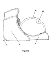
- a cycle stand according to a first embodiment of the invention comprises a body 2 formed by rotational moulding from a plastics material such as medium density polyethylene.
- the plastics material may be a recycled material.
- the body 2 has an elongate horizontally extending base portion 4 and an upright portion 6 which has two moulded bays or pockets 8,10 each of which is shaped to receive a wheel of a bicycle.
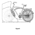
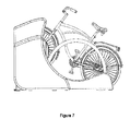
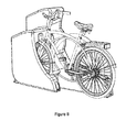
- the pocket is shown accommodating the front wheel of a bicycle.
- the left hand (nearside) bay or pocket 8 is part circular when viewed from the side and is open at the bottom by virtue of a relatively narrow slot 3 which is sufficiently wide to take a bicycle wheel.
- the pocket opens out to provide a wider region 5 that can accommodate wheel hubs and their associated nuts and release levers, or fixtures such as lamps or reflectors mounted on the fork of the bicycle.
- the wider region 5 is a second narrower region 7 which corresponds approximately in width to the lower narrower region 3.
- the upper narrower region 7 accommodates the top of a wheel of the bicycle.
- the wheel (e.g. front wheel) of a bicycle can be inserted into the slot 3 of the pocket 8 so that the wheel rests on the ground.
- the depth of the pocket 8 is such that it can accommodate all of the standard wheel sizes currently in use. Consequently, the bicycle wheel can be inserted into the pocket to a depth greater than the radius of the wheel and this in turn means that the axle and preferably the entire wheel hub are within the pocket. Because the pocket is also of restricted width, it is difficult or impossible for a tool to be inserted into the gap between the pocket wall and wheel to undo the wheel nut or wheel release lever. In this way, theft of the wheel is prevented.
- the right hand (far side) pocket 10 is also part circular when viewed from the side and is raised with respect to the left hand pocket.
- the pocket 10 has an entrance ramp 12 leading to a lip 14, the other side of which is a curved wheel-supporting surface 16.
- the far side pocket widens out above the wheel-supporting surface to provide a wider space 18 that can accommodate wheel hubs and their associated nuts and release levers, or fixtures such as lamps or reflectors mounted on a fork of the bicycle.
- the side walls 42 of the far side pocket 10 are bowed outwardly so as to cover a greater area of the wheel and restrict or prevent access to the wheel hub and wheel nuts.
- the plastics body 2 is provided with a plurality of anchoring points 20, 22, 24, 26 and 28 through which anchoring bolts or other securing elements can be inserted to secure the body to an underlying substrate such as a paved area or concrete base.
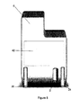
- the cycle stand has a curved rail 30 formed from a metal such as stainless steel.
- the two ends of the rail extend through holes in the body 4 and terminate in feet 36, 38 each of which comprise a rectangular flange or fastening plate through which bolts (not shown) are located to anchor the feet in an underlying substrate (e.g. a concrete base).
- a loop of metal 40 is welded to an underside of the rail 30.
- the loop 40 acts as an anchoring member to which the bicycle may be secured by means of a locking device such as a chain and padlock or combination lock.
- a locking device such as a chain and padlock or combination lock.
- Figure 5 is a rear view of the body 2.
- the rear surface of the body has a rectangular recessed area 42 which can be used to carry advertising material.
- the area 42 may carry a flat panel electronic display for showing advertising or public information materials.
- Power for the display can be provided by means of a battery, a connection to a local electricity supply, or (most preferably) by means of a solar panel (not shown) mounted on the body.
Landscapes
- Engineering & Computer Science (AREA)
- Mechanical Engineering (AREA)
- Illuminated Signs And Luminous Advertising (AREA)
- Photovoltaic Devices (AREA)
- Vehicle Step Arrangements And Article Storage (AREA)
Applications Claiming Priority (1)
| Application Number | Priority Date | Filing Date | Title |
|---|---|---|---|
| GB201004077A GB2480800B (en) | 2010-03-12 | 2010-03-12 | Cycle stand |
Publications (2)
| Publication Number | Publication Date |
|---|---|
| EP2364900A2 true EP2364900A2 (fr) | 2011-09-14 |
| EP2364900A3 EP2364900A3 (fr) | 2013-01-02 |
Family
ID=42261437
Family Applications (1)
| Application Number | Title | Priority Date | Filing Date |
|---|---|---|---|
| EP11002096A Withdrawn EP2364900A3 (fr) | 2010-03-12 | 2011-03-14 | Support de bicyclette |
Country Status (2)
| Country | Link |
|---|---|
| EP (1) | EP2364900A3 (fr) |
| GB (1) | GB2480800B (fr) |
Cited By (2)
| Publication number | Priority date | Publication date | Assignee | Title |
|---|---|---|---|---|
| US10843752B2 (en) | 2018-05-14 | 2020-11-24 | David Lee Sawhill | Integrated bicycle rack and lock station |
| US11225297B2 (en) | 2018-05-14 | 2022-01-18 | David Lee Sawhill | Integrated bicycle rack and lock station |
Family Cites Families (10)
| Publication number | Priority date | Publication date | Assignee | Title |
|---|---|---|---|---|
| US3865245A (en) * | 1972-03-01 | 1975-02-11 | Rally Enterprises Inc | Bicycle rack |
| DE8214601U1 (de) * | 1982-05-19 | 1982-09-23 | Caspar Hessel GmbH & Co KG, 4400 Münster | Fahrradstaender |
| CH683248A5 (de) * | 1992-03-30 | 1994-02-15 | Eric Misselwitz Hansjoerg Muel | Fahrradständer. |
| GB9219251D0 (en) * | 1992-09-11 | 1992-10-28 | Dixon Bate Limited B | Improvements relating to devices for use in securing a bicycle against theft |
| DE29606059U1 (de) * | 1996-04-01 | 1996-06-20 | Eisen- Und Drahtwerk Erlau Ag, 73431 Aalen | Ständer für Fahrräder |
| GB2312882A (en) * | 1996-05-11 | 1997-11-12 | Charles William Withers | Bicycle stand |
| DE202006004849U1 (de) * | 2006-03-22 | 2006-06-14 | Riemann, Herbert | Mobiler Fahrradvermietautomat (Fahrradmietpunkt) |
| DE202006004742U1 (de) * | 2006-03-24 | 2006-07-06 | Schreiter, Peter | Fahrradständer mit stationärem Automatik Fahrradschloß |
| DE102008009012B3 (de) * | 2008-02-13 | 2009-02-26 | ASTRA Gesellschaft für Asset Management mbH & Co. KG | Fahrradsicherungssystem |
| NL1035058C1 (nl) * | 2008-02-20 | 2009-08-24 | Jeroen Bastiaan Van Tongeren | Fietsparkeerinrichting met antidiefstalvoorziening. |
-
2010
- 2010-03-12 GB GB201004077A patent/GB2480800B/en active Active
-
2011
- 2011-03-14 EP EP11002096A patent/EP2364900A3/fr not_active Withdrawn
Non-Patent Citations (1)
| Title |
|---|
| None |
Cited By (2)
| Publication number | Priority date | Publication date | Assignee | Title |
|---|---|---|---|---|
| US10843752B2 (en) | 2018-05-14 | 2020-11-24 | David Lee Sawhill | Integrated bicycle rack and lock station |
| US11225297B2 (en) | 2018-05-14 | 2022-01-18 | David Lee Sawhill | Integrated bicycle rack and lock station |
Also Published As
| Publication number | Publication date |
|---|---|
| GB201004077D0 (en) | 2010-04-28 |
| EP2364900A3 (fr) | 2013-01-02 |
| GB2480800A (en) | 2011-12-07 |
| GB2480800B (en) | 2014-10-15 |
Similar Documents
| Publication | Publication Date | Title |
|---|---|---|
| US9908576B2 (en) | Modular bicycle storage structure | |
| KR100910008B1 (ko) | 수직거치식 자전거 주차장치 | |
| US11148740B2 (en) | Scooter rack | |
| JP7727079B2 (ja) | 電子ロックを備えるスタンドに自転車をロックするための駐輪スタンド | |
| US11370501B2 (en) | Space-saving bicycle parking structure | |
| KR20150056729A (ko) | 자전거 보관용 주차장치 | |
| EP2364900A2 (fr) | Support de bicyclette | |
| US4506786A (en) | Bicycle storage structure | |
| US5653890A (en) | Bicycle storage system | |
| GB2545369A (en) | Storage | |
| GB2265346A (en) | Cycle security device | |
| KR200455684Y1 (ko) | 자전거 거치대의 바퀴 고정구 | |
| KR20110034955A (ko) | 자전거 보관대 | |
| GB2557330A (en) | Motorbike wheel lock and ground anchor | |
| GB2465340A (en) | Motorcycle security frame | |
| GB2512033A (en) | Bicycle parking apparatus | |
| KR200463494Y1 (ko) | 자전거 주차대 | |
| KR101282097B1 (ko) | 모래 보관함 | |
| CZ202420A3 (cs) | Podúrovňový stojan pro bicykl | |
| CN202400199U (zh) | 一种停车架 | |
| SG193066A1 (en) | Device for securing a bicycle | |
| KR100996319B1 (ko) | 자전거보관용 주차장치 | |
| PL245342B1 (pl) | Stojak rowerowy z antykradzieżową blokadą | |
| HK1202496B (en) | Device for securing a bicycle | |
| SG193030A1 (en) | Device for securing a bicycle |
Legal Events
| Date | Code | Title | Description |
|---|---|---|---|
| PUAI | Public reference made under article 153(3) epc to a published international application that has entered the european phase |
Free format text: ORIGINAL CODE: 0009012 |
|
| AK | Designated contracting states |
Kind code of ref document: A2 Designated state(s): AL AT BE BG CH CY CZ DE DK EE ES FI FR GB GR HR HU IE IS IT LI LT LU LV MC MK MT NL NO PL PT RO RS SE SI SK SM TR |
|
| AX | Request for extension of the european patent |
Extension state: BA ME |
|
| PUAL | Search report despatched |
Free format text: ORIGINAL CODE: 0009013 |
|
| AK | Designated contracting states |
Kind code of ref document: A3 Designated state(s): AL AT BE BG CH CY CZ DE DK EE ES FI FR GB GR HR HU IE IS IT LI LT LU LV MC MK MT NL NO PL PT RO RS SE SI SK SM TR |
|
| AX | Request for extension of the european patent |
Extension state: BA ME |
|
| RIC1 | Information provided on ipc code assigned before grant |
Ipc: B62H 3/08 20060101AFI20121128BHEP Ipc: B62H 3/04 20060101ALI20121128BHEP Ipc: B62H 3/02 20060101ALI20121128BHEP |
|
| STAA | Information on the status of an ep patent application or granted ep patent |
Free format text: STATUS: THE APPLICATION IS DEEMED TO BE WITHDRAWN |
|
| 18D | Application deemed to be withdrawn |
Effective date: 20130703 |