EP2364944A2 - Rouleau de bande - Google Patents
Rouleau de bande Download PDFInfo
- Publication number
- EP2364944A2 EP2364944A2 EP11169467A EP11169467A EP2364944A2 EP 2364944 A2 EP2364944 A2 EP 2364944A2 EP 11169467 A EP11169467 A EP 11169467A EP 11169467 A EP11169467 A EP 11169467A EP 2364944 A2 EP2364944 A2 EP 2364944A2
- Authority
- EP
- European Patent Office
- Prior art keywords
- reel
- projection
- adhesive
- tape
- wound
- Prior art date
- Legal status (The legal status is an assumption and is not a legal conclusion. Google has not performed a legal analysis and makes no representation as to the accuracy of the status listed.)
- Withdrawn
Links
Images



Classifications
-
- B—PERFORMING OPERATIONS; TRANSPORTING
- B65—CONVEYING; PACKING; STORING; HANDLING THIN OR FILAMENTARY MATERIAL
- B65H—HANDLING THIN OR FILAMENTARY MATERIAL, e.g. SHEETS, WEBS, CABLES
- B65H75/00—Storing webs, tapes, or filamentary material, e.g. on reels
- B65H75/02—Cores, formers, supports, or holders for coiled, wound, or folded material, e.g. reels, spindles, bobbins, cop tubes, cans, mandrels or chucks
- B65H75/04—Kinds or types
- B65H75/08—Kinds or types of circular or polygonal cross-section
- B65H75/14—Kinds or types of circular or polygonal cross-section with two end flanges
-
- B—PERFORMING OPERATIONS; TRANSPORTING
- B65—CONVEYING; PACKING; STORING; HANDLING THIN OR FILAMENTARY MATERIAL
- B65H—HANDLING THIN OR FILAMENTARY MATERIAL, e.g. SHEETS, WEBS, CABLES
- B65H75/00—Storing webs, tapes, or filamentary material, e.g. on reels
- B65H75/02—Cores, formers, supports, or holders for coiled, wound, or folded material, e.g. reels, spindles, bobbins, cop tubes, cans, mandrels or chucks
- B65H75/04—Kinds or types
- B65H75/08—Kinds or types of circular or polygonal cross-section
-
- B—PERFORMING OPERATIONS; TRANSPORTING
- B65—CONVEYING; PACKING; STORING; HANDLING THIN OR FILAMENTARY MATERIAL
- B65H—HANDLING THIN OR FILAMENTARY MATERIAL, e.g. SHEETS, WEBS, CABLES
- B65H2701/00—Handled material; Storage means
- B65H2701/30—Handled filamentary material
- B65H2701/37—Tapes
- B65H2701/377—Adhesive tape
Definitions
- the invention relates to a reel for winding an adhesive tape (a sticky tape) obtained by cutting into a narrow tape a film material on which an adhesive layer (or a sticky layer) is formed.
- an anisotropic conductive film obtained by incorporating conductive fine particles into an adhesive layer formed on a substrate is widely used in circuit connection of liquid crystal displays.
- this type of anisotropic conductive file' is manufactured and supplied by a method in which an adhesive layer is formed by coating or the like on a wide film material and the resultant is cut into a narrow tape.
- Patent Document 1 JP-A-2003-34468
- the inventors made extensive studies. As a result, the inventors have found that, in producing an anisotropic conductive film, there is yet room for improvement in the production method in which a film material on which an adhesive layer is formed by coating is wound around a reel while cutting it into a narrow tape. Specifically, during winding around a reel or during storage of the wound tape, an adhesive forming the adhesive layer tends to adhere to the inner surface of the reel, resulting in formation of defective products.
- An object of the invention in manufacturing and supplying an adhesive film (tape) such as an anisotropic conductive film by a method in which a film material on which an adhesive layer is formed by coating is wound around a reel while cutting it into a narrow tape, is to provide a reel which can prevent adherence of an adhesive to the inner surface of the reel to improve yield, as well as ensure stable unwinding of the adhesive tape for use.
- an adhesive film such as an anisotropic conductive film
- the reel of the invention which solves the above-mentioned problem, comprises a columnar wind-up unit and a pair of opposing side plates provided such that the wind-up unit is between the side plates, wherein the inner surface of one or both of the side plates is provided with a projection which extends continuously or intermittently.
- the reel of the invention with the above-mentioned configuration has a novel shape which cannot be found in conventional reels. If adhesive tapes are manufactured and supplied by a method in which a film material on which an adhesive layer is formed by coating is wound up around the reel of the invention while cutting it into a narrow tape, it is possible to prevent an adhesive constituting the adhesive layer from adhering to the inner surface of the reel during manufacturing or storage after winding.
- the reel of the invention can be configured such that the above-mentioned projection extends in the radial direction.
- the reel it is preferred that the reel have a configuration in which the above-mentioned projections are provided radially.
- the above-mentioned radially-directed projection be 0.05 to 1.00 mm in height and 0.5 to 20.0 mm in width.
- the reel according to the invention may have a configuration in which a peripheral projection extending in the circumferential direction thereof is provided on the inner surface along the peripheral part of one or both of the above-mentioned side plates. Due to such a configuration, when the adhesive tape is wound while preventing un-uniform winding by guiding the side surface of the adhesive tape, which is the object being wound, with the peripheral part of the side plate, it is possible to reduce the area of the adhesive tape in contact with the peripheral part, whereby adherence of the adhesive to the peripheral part of the side plate can be prevented.
- the reel of the invention in order to reduce the area of the adhesive tape in contact with the peripheral part, which is the object being wound, when winding the adhesive tape while guiding the side surface thereof with the peripheral part of the side plate, it is preferred that at least part of the peripheral projection which is in contact with the object be circular in shape.
- the projection be 0.05 to 1.00 mm in height and 0.5 to 20.0 mm in width.
- the object being wound can be provided with an adhesive layer or a sticky layer.
- the reel of the invention can preferably be applied to the object being wound, which is provided with a sticky layer formed by applying a material generally known as a "sticky adhesive", and thus adherence of a sticky adhesive can be prevented.
- FIG. 1 is an explanatory view showing the outline of the reel according to the invention, in which FIG. 1(a) is a front view and FIG. 1(b) is a cross sectional view of FIG. 1(a) taken along the line A-A in FIG. 1(a) .
- a reel 1 shown in FIG. 1 is provided with a columnar wind-up unit 3 and a pair of side plates 2 and 2 provided in parallel with or substantially in parallel with each other such that a wind-up unit 3 is between the side plates.
- a D-shaped shaft hole 4 penetrates through almost the center of the reel 1.
- the reel 1 with such a configuration is used for manufacturing and supplying various adhesive tapes 5 by a method in which a film material on which an adhesive layer is formed by coating is cut into a narrow tape and the narrow tape is wound around the reel.
- the width of the wind-up unit 3, namely the distance between the side plates 2 and 2 which are separated by the wind-up unit 3 can be appropriately set according to the cut width of an adhesive tape 5 as the object being wound.
- the side plate 2 is normally formed in a circular shape, and the diameter thereof can be appropriately set according to the winding length of the adhesive tape 5.
- the reel 1 may be a reel which is integrally formed by injection molding or the like.
- the pair of the side plates 2 and 2 and the wind-up unit 3 may be formed separately, and these parts may be connected by an appropriate means such as fitting and adhesion.
- the side plates 2 and 2 and the wind-up unit 3 separately, the following configuration can be realized.
- the side plates 2 differing in diameter can be combined with the common wind-up unit 3, thereby allowing the reel 1 to correspond to various winding lengths, or the wind-up units 3 differing in width can be combined with the common side plate 2, thereby allowing the reel to correspond to various cutting widths.
- a projection 21 extending in the radial direction is provided on the inner surface of the side plates 2 and 2.
- Fig. 2 is an end view taken along the line B-B in FIG. 1(b) .
- the projection 21 provided on the inner surface of the side plate 2 serves to avoid contact of the adhesive layer exposed on the side surface of an adhesive tape 4 with the inner surface of the reel 1 (inner surface of the side plate 2) when winding up the adhesive tape 5 around the reel 1 or during the storage of the wound adhesive tape 5, whereby the adhesive constituting the adhesive layer is prevented from adhering to the inner surface of the reel 1.
- the distance between the side plates 2 and 2, which are separated by the wind-up unit 3, is set to be larger to some extent than the cut width of the adhesive tape 5 such that the adhesive tape 5 to be wound around the wind-up unit 3 is prevented from being adhered to the inner surface of the side plate 2. Even with this distance, if the winding position of the adhesive tape 5 is shifted due to irregular rotation or the like of the reel 1 during winding of the adhesive tape 5, or the position of the adhesive tape 5 which has been wound is shifted due to impact or vibration during storage, the adhesive tape 5 may come in contact with the inner surface of the side plate 2.
- the height hl of the projection 21 is preferably 0.05 to 1.00 mm, more preferably 0.05 to 0.30 mm, and particularly preferably 0.05 to 0.20 mm. If the height hl of the projection 21 is less than 0.05 mm, it may be hard to obtain the effects of suppressing contact of the adhesive tape 5 with the inner surface of the side plate 2. In addition, the height hl of less than 0.05 mm is not preferable, since the injection molding conditions of the reel 1 are required to be controlled accurately. On the other hand, if the height hl of the projection 21 exceeds 1.00 mm, the projection 21 becomes excessively high, affecting the width dimensions of the reel 1. In addition, this height is not preferable since pushing pressure to the side surface of the adhesive tape 5 increases, and as a result, the side surface of the adhesive tape 5 may acquire marks from the projection 21.
- the width w1 of the projection 21 is preferably 0.5 to 20.0 mm, more preferably 0.5 to 10.0 mm, and particularly preferably 0.5 to 5.0 mm. If the width w1 of the projections 21 is less than 0.5 mm, the side surface of the adhesive tape 5 may become damaged. In addition, the width w1 of the projection 21 of less than 0.5 mm is not preferable since the injection molding conditions of the reel 1 are required to be controlled accurately. On the other hand, when the width w1 of the projection 21 exceeds 20.0 mm, the adhesive may adhere to the projection 21.
- FIG. 3 is an end view showing the cross section taken along the line C-C in FIG. 1(b) .
- FIG. 4 is an explanatory view showing the winding-up state of the adhesive tape 5.
- FIG. 4(b) is a left side view of the state shown in FIG. 4(a) .
- the adhesive tape 5 is wound around the reel 1 which rotates in the direction shown by the arrow.
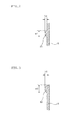
- the peripheral projection 22 provided on the inner surface along the peripheral part of the side plate 2 serves to prevent adherence of the adhesive constituting the adhesive layer to the peripheral part of the side plate 2, which is caused by the contact of the adhesive layer exposed on the side surface of the adhesive tape 5 with the peripheral part of the side plate 2 when winding the adhesive tape 5 around the reel 1 as mentioned above.
- the peripheral projection 22 extending in the circumference direction is provided on the inner surface along the peripheral part of the side plate 2 to suppress the adhesion of the adhesive.
- the peripheral projection 22 which is in contact with the adhesive tape 5 have a circular shape.
- the radius of curvature thereof is preferably 0.3 to 1.5 mm, more preferably 0.5 to 1.0 mm in order to reduce the contact area of the peripheral projection 21 with the adhesive tape 5.
- the height h2 of the peripheral projection 22 is preferably 0.05 to 1.00 mm, more preferably 0.05 to 0.30 mm, and particularly preferably 0.05 to 0.20 mm. If the height h2 of the peripheral projection 22 is less than 0.05 mm, the effects of suppressing contact of the adhesive tape 5 with the inner surface of the side plate 2 are impaired. In addition, such a small height of the peripheral projection 22 is not preferable since the adhesive tape 5 may become scratched due to interference of the projection 21 and the adhesive tape 5 when winding the adhesive tape 5.
- the peripheral projection 22 If the height h2 of the peripheral projection 22 exceeds 1.00 mm, the peripheral projection 22 becomes excessively high, and as a result, the peripheral projection 22 may interfere with the adhesive tape 5 when winding up the adhesive tape 5. In addition, since the gap between the wound adhesive tape 5 and the side plates 2 and 2 increases after winding of the adhesive tape 5 is completed, weaving may occur during storage, resulting in lowered storage stability.
- the width w2 of the peripheral projection 22 is preferably 0.5 to 20.0 mm, more preferably 0.5 to 10.0 mm, and particularly preferably 0.5 to 5.0 mm. If the width w2 of the peripheral projection 22 is less than 0.5 mm, the side surface of the adhesive tape 5 may become scratched. If the width w2 of the peripheral projection 22 exceeds 20.0 mm, the problem of adherence of the adhesive to the peripheral projection 22 occurs. In addition, when the adhesive tape 5 which has been wound up around the reel 1 is unwound for use, the adhesive tape 5 may become caught in the peripheral projection 22.
- both of the pair of side plates 2 and 2 are provided with the radially-directed projection 21 or the peripheral projection 22.
- the radially-directed projection 21 and the peripheral projection 22 may be provided on only one of the side plates 2 and 2. That is, if the adhesive tape 5 is wound near one of the side plates 2 in order to increase the distance between the other side plate 2 and the adhesive tape 5, the radially-directed projection 2l' and the peripheral projection 22 can be provided on the one side plate 2.
- the shaft hole 4 in the shape of the letter D is shown.
- the shaft hole 4 may contain a key groove corresponding to a key provided on the winding shaft.
- the specific configuration of the shaft hole 4 can be changed corresponding to a means for mounting the winding apparatus to the winding shaft.
- the winding unit 3 may have various configurations which can be applied to this type of reel, for example, provision of a rib for ensuring rigidity.
- the adhesive tape 5 provided with an adhesive layer is used as an object to be wound.
- the reel of the invention can preferably be applied to an object to be wound provided with a sticky layer formed by applying a material generally known as a "sticky adhesive".
- the projections 21 provided on the inner surface of the side plate 2 are provided as a concave line formed continuously from the inner perimeter to the outer perimeter of the reel 1.
- the projections 21 may be formed intermittently.
- the projections 21 may be provided from the center of the side plate 2 to the periphery so that they extend in the radial direction.
- the projections 21 may be provided such that they intersect with the radial direction, and, as shown in FIG. 5(c) , the projections 21 may be provided in a spiral shape.
- the projections 21 are provided radially, the radial center thereof is preferably the same as the center of the side plate 2. However, it is possible to allow the radial center and the center of the side plate 2 to be different, if necessary. Furthermore, it is possible to form the projections 21 in such a manner that the projections 21 extend radially from each of these different radial centers.
- the shape of the cross section of the projection 21 is not limited to the above-mentioned circular shape.
- the cross section may have a rectangular shape or a rectangular shape with round corners, or the like.
- the cross section may have a shape as shown in FIG. 6 .
- the peripheral projection 22 is provided along the entire circumference of the peripheral part of the side plate 2.
- the peripheral projection may be provided intermittently along the peripheral part of the side plate 2.
- the peripheral projection may be provided in a spiral form, and as shown in FIG. 7(c) , a plurality of (2 in the in the shown example) peripheral projections 22 may be arranged in parallel to each other.
- the peripheral projections 22 provided intermittently may be connected with the projections 21, which is provided to avoid adherence of the adhesive to the inner surface of the reel 1.
- the cross section of the peripheral projection 22 may have the same shape as that of the projection 21. Specifically, it may have a circular shape, a rectangular shape, a rectangular shape with round corners, or a shape shown in FIG. 6 .
- FIGs. 5 , 7 and 8 are explanatory views which conceptually show the positions of the projections 21 and 22 in the above-mentioned modification example.
- FIG. 6 is an explanatory view which shows the outline of the shape of the cross section of the projection 21 (or peripheral projection 22).
- FIGs. 6(d) and (f) show two projections 21 (or peripheral projections 22) which are arranged in parallel in such a manner that they are dose to each other
- FIGs. 6(e) and (g) show two projections 21 (or peripheral projections 22) which are arranged in such a manner that they are in contact with each other.
- the invention provides a reel used to manufacture and supply an adhesive tape, which prevents adherence of an adhesive to the inner surface thereof.
Landscapes
- Storage Of Web-Like Or Filamentary Materials (AREA)
- Adhesive Tapes (AREA)
Applications Claiming Priority (2)
| Application Number | Priority Date | Filing Date | Title |
|---|---|---|---|
| JP2006170961 | 2006-06-21 | ||
| EP07745221A EP2030936A4 (fr) | 2006-06-21 | 2007-06-14 | Bobine |
Related Parent Applications (1)
| Application Number | Title | Priority Date | Filing Date |
|---|---|---|---|
| EP07745221.7 Division | 2007-06-14 |
Publications (2)
| Publication Number | Publication Date |
|---|---|
| EP2364944A2 true EP2364944A2 (fr) | 2011-09-14 |
| EP2364944A3 EP2364944A3 (fr) | 2011-12-21 |
Family
ID=38833335
Family Applications (3)
| Application Number | Title | Priority Date | Filing Date |
|---|---|---|---|
| EP11169467A Withdrawn EP2364944A3 (fr) | 2006-06-21 | 2007-06-14 | Rouleau de bande |
| EP11169468A Withdrawn EP2368828A3 (fr) | 2006-06-21 | 2007-06-14 | Bobine |
| EP07745221A Withdrawn EP2030936A4 (fr) | 2006-06-21 | 2007-06-14 | Bobine |
Family Applications After (2)
| Application Number | Title | Priority Date | Filing Date |
|---|---|---|---|
| EP11169468A Withdrawn EP2368828A3 (fr) | 2006-06-21 | 2007-06-14 | Bobine |
| EP07745221A Withdrawn EP2030936A4 (fr) | 2006-06-21 | 2007-06-14 | Bobine |
Country Status (7)
| Country | Link |
|---|---|
| US (3) | US20090230233A1 (fr) |
| EP (3) | EP2364944A3 (fr) |
| JP (4) | JPWO2007148593A1 (fr) |
| KR (1) | KR101330861B1 (fr) |
| CN (3) | CN101479176A (fr) |
| TW (3) | TW200825011A (fr) |
| WO (1) | WO2007148593A1 (fr) |
Families Citing this family (16)
| Publication number | Priority date | Publication date | Assignee | Title |
|---|---|---|---|---|
| WO2011118503A1 (fr) * | 2010-03-23 | 2011-09-29 | 日立化成工業株式会社 | Bobine de ruban adhésif |
| KR101940349B1 (ko) * | 2011-07-08 | 2019-01-18 | 히타치가세이가부시끼가이샤 | 접착 테이프용 릴, 권중체, 곤포물, 릴의 접착 테이프를 권회하기 위한 접착 테이프용 릴로서의 용도, 및 접착 테이프용 릴의 제조 방법 |
| JP5930274B2 (ja) * | 2011-12-05 | 2016-06-08 | デクセリアルズ株式会社 | リール部材及びフィルム収容体 |
| JP5982159B2 (ja) * | 2012-04-06 | 2016-08-31 | デクセリアルズ株式会社 | リール部材、接着フィルムの巻回方法、接着フィルムの巻き出し方法 |
| JP5982158B2 (ja) * | 2012-04-06 | 2016-08-31 | デクセリアルズ株式会社 | リール部材 |
| JP5939504B2 (ja) * | 2012-05-02 | 2016-06-22 | ブラザー工業株式会社 | テープ巻き取り装置及び巻芯部材 |
| JP5905351B2 (ja) * | 2012-07-04 | 2016-04-20 | デクセリアルズ株式会社 | リール部材及びフィルム収容体 |
| JP6197395B2 (ja) * | 2012-07-20 | 2017-09-20 | 日立化成株式会社 | 接着テープ用リール及びテープ |
| JP6202033B2 (ja) * | 2014-05-15 | 2017-09-27 | 株式会社村田製作所 | テーピング電子部品連用リール及びその製造方法 |
| KR20190035956A (ko) * | 2015-02-27 | 2019-04-03 | 데쿠세리아루즈 가부시키가이샤 | 릴체, 필름 연결체, 필름 권취 장착체 및 필름 연결체의 제조 방법 |
| CN106364989A (zh) * | 2015-07-21 | 2017-02-01 | 刘程秀 | 一种带状物承载体 |
| JP6905320B2 (ja) * | 2016-09-27 | 2021-07-21 | デクセリアルズ株式会社 | 接着フィルム巻装体、接着フィルム巻装体の製造方法 |
| JP7325706B2 (ja) * | 2018-07-18 | 2023-08-15 | マックス株式会社 | 結束用テープ、結束方法、テープ巻き付け体及びリール |
| TWI767131B (zh) | 2018-07-18 | 2022-06-11 | 日商美克司股份有限公司 | 捆束用帶 |
| JP7595411B2 (ja) | 2019-11-22 | 2024-12-06 | デクセリアルズ株式会社 | リール部材、接着フィルム巻装体 |
| US20240299856A1 (en) * | 2023-03-10 | 2024-09-12 | Nelson Companies One, LLC | Balloon weight and ribbon assembly with adhesive film peel-assist feature |
Citations (1)
| Publication number | Priority date | Publication date | Assignee | Title |
|---|---|---|---|---|
| JP2003034468A (ja) | 2001-02-16 | 2003-02-07 | Sony Chem Corp | リール部材及びフィルムの巻取り方法 |
Family Cites Families (30)
| Publication number | Priority date | Publication date | Assignee | Title |
|---|---|---|---|---|
| US1951151A (en) * | 1933-07-21 | 1934-03-13 | Metal Package Corp | Tape spool |
| GB869979A (en) * | 1959-02-17 | 1961-06-07 | Hallmark Cards | Improvements in or relating to spools for decorative or other ribbon |
| US2973159A (en) * | 1959-08-17 | 1961-02-28 | Thomas S Kulka | Friction reducing tape reel |
| US3099414A (en) * | 1961-02-27 | 1963-07-30 | Thomas S Kuika | Tape reel having friction reducing means |
| FR1313449A (fr) * | 1962-01-23 | 1962-12-28 | Bague en matière plastique | |
| US3342435A (en) * | 1966-04-11 | 1967-09-19 | Data Packaging Corp | Reel with tape guide |
| JPS5443246Y2 (fr) * | 1971-05-11 | 1979-12-14 | ||
| JPS5647175Y2 (fr) * | 1976-10-27 | 1981-11-05 | ||
| JPS5363379A (en) * | 1976-11-17 | 1978-06-06 | Nippon Kayaku Co Ltd | Preparation of 2-phenylbenzotriazoles or their n-oxides |
| JPS56135965U (fr) * | 1980-03-17 | 1981-10-15 | ||
| JPS56140557U (fr) * | 1980-03-19 | 1981-10-23 | ||
| JPS56135965A (en) * | 1980-03-28 | 1981-10-23 | Nec Corp | Semiconductor device |
| JPS56140557A (en) * | 1980-04-04 | 1981-11-02 | Pioneer Electronic Corp | Bookshelf type record player |
| USD298541S (en) * | 1985-12-17 | 1988-11-15 | Strapack Corporation | Reel plate for a strapping machine |
| US4726534A (en) * | 1986-08-06 | 1988-02-23 | Advantek Inc. | Convertible reel assembly |
| JPS6490763A (en) * | 1987-10-01 | 1989-04-07 | Seiko Epson Corp | Wire dot head |
| JPH0190763U (fr) * | 1987-12-07 | 1989-06-14 | ||
| JP2570366Y2 (ja) * | 1993-01-29 | 1998-05-06 | 信越ポリマー株式会社 | キャリアテープ用リール |
| US5474254A (en) * | 1994-11-08 | 1995-12-12 | Faulkner Fabricators, Inc. | Spool and method of making same |
| USD370908S (en) * | 1995-09-08 | 1996-06-18 | Alpha Enterprises, Inc. | Tape reel flange |
| JPH09278291A (ja) * | 1996-04-16 | 1997-10-28 | Toshiba Corp | テープ巻取リール |
| CN1152383C (zh) * | 1996-05-30 | 2004-06-02 | 可隆株式会社 | 用于缠绕感光膜的卷筒 |
| US6598825B2 (en) * | 1998-02-13 | 2003-07-29 | C. Robert Ripplinger | Simultaneous-access surfaces for reel-flange fasteners |
| JP3945076B2 (ja) | 1999-06-30 | 2007-07-18 | ブラザー工業株式会社 | テープカセット |
| DE29918667U1 (de) * | 1999-10-22 | 1999-12-30 | BIC Deutschland GmbH & Co, 65835 Liederbach | Handgerät zum Übertragen eines Filmes von einem Trägerband auf ein Substrat, mit einer Rücklaufsperre |
| US6435451B1 (en) * | 2000-10-19 | 2002-08-20 | Storage Technology Corporation | Compliant tape reel flanges |
| JP2003031990A (ja) | 2001-07-11 | 2003-01-31 | Sanyo Electric Co Ltd | 部品供給装置 |
| US20040140392A1 (en) * | 2003-01-21 | 2004-07-22 | George Saliba | Butterfly tape reel |
| US7073742B2 (en) * | 2003-01-21 | 2006-07-11 | Quantum Corporation | Tape guiding reel |
| CN102070048B (zh) * | 2006-06-21 | 2016-02-03 | 日立化成株式会社 | 带的卷绕方法 |
-
2007
- 2007-06-14 EP EP11169467A patent/EP2364944A3/fr not_active Withdrawn
- 2007-06-14 CN CNA2007800228590A patent/CN101479176A/zh active Pending
- 2007-06-14 EP EP11169468A patent/EP2368828A3/fr not_active Withdrawn
- 2007-06-14 KR KR1020087030993A patent/KR101330861B1/ko active Active
- 2007-06-14 US US12/306,250 patent/US20090230233A1/en not_active Abandoned
- 2007-06-14 JP JP2008522411A patent/JPWO2007148593A1/ja active Pending
- 2007-06-14 CN CN2011100252916A patent/CN102107803A/zh active Pending
- 2007-06-14 WO PCT/JP2007/061964 patent/WO2007148593A1/fr not_active Ceased
- 2007-06-14 EP EP07745221A patent/EP2030936A4/fr not_active Withdrawn
- 2007-06-14 CN CN2011100252808A patent/CN102085983B/zh active Active
- 2007-06-21 TW TW096122289A patent/TW200825011A/zh unknown
- 2007-06-21 TW TW099139965A patent/TW201125803A/zh unknown
- 2007-06-21 TW TW099139967A patent/TW201125804A/zh not_active IP Right Cessation
-
2010
- 2010-11-01 JP JP2010245529A patent/JP5024444B2/ja active Active
- 2010-12-01 JP JP2010268264A patent/JP2011089126A/ja active Pending
-
2011
- 2011-02-22 US US13/032,599 patent/US20110139922A1/en not_active Abandoned
- 2011-02-22 US US13/032,615 patent/US20110139916A1/en not_active Abandoned
- 2011-12-20 JP JP2011278716A patent/JP5293802B2/ja active Active
Patent Citations (1)
| Publication number | Priority date | Publication date | Assignee | Title |
|---|---|---|---|---|
| JP2003034468A (ja) | 2001-02-16 | 2003-02-07 | Sony Chem Corp | リール部材及びフィルムの巻取り方法 |
Also Published As
| Publication number | Publication date |
|---|---|
| TW200825011A (en) | 2008-06-16 |
| WO2007148593A1 (fr) | 2007-12-27 |
| KR101330861B1 (ko) | 2013-11-18 |
| EP2030936A4 (fr) | 2010-12-22 |
| JPWO2007148593A1 (ja) | 2009-11-19 |
| EP2368828A3 (fr) | 2011-12-21 |
| TWI360510B (fr) | 2012-03-21 |
| JP2011020859A (ja) | 2011-02-03 |
| EP2364944A3 (fr) | 2011-12-21 |
| CN101479176A (zh) | 2009-07-08 |
| EP2368828A2 (fr) | 2011-09-28 |
| JP2012057176A (ja) | 2012-03-22 |
| JP5293802B2 (ja) | 2013-09-18 |
| KR20090018831A (ko) | 2009-02-23 |
| US20110139916A1 (en) | 2011-06-16 |
| JP2011089126A (ja) | 2011-05-06 |
| US20090230233A1 (en) | 2009-09-17 |
| TW201125803A (en) | 2011-08-01 |
| CN102107803A (zh) | 2011-06-29 |
| CN102085983B (zh) | 2013-05-01 |
| TWI360511B (fr) | 2012-03-21 |
| JP5024444B2 (ja) | 2012-09-12 |
| CN102085983A (zh) | 2011-06-08 |
| EP2030936A1 (fr) | 2009-03-04 |
| TW201125804A (en) | 2011-08-01 |
| US20110139922A1 (en) | 2011-06-16 |
Similar Documents
| Publication | Publication Date | Title |
|---|---|---|
| EP2364944A2 (fr) | Rouleau de bande | |
| US20110198433A1 (en) | Reel | |
| JP5192320B2 (ja) | ポリマーフィルムの巻取方法及びその装置 | |
| CN103097269B (zh) | 卷绕用芯、卷绕用卷筒、及带体的卷绕方法 | |
| JP2019005926A (ja) | 塗膜転写具 | |
| JP5835905B2 (ja) | ロールの製造方法 | |
| JP2009149397A (ja) | 接着テープ用リール | |
| JP5050832B2 (ja) | 接着テープ用リール | |
| CN115443423A (zh) | 具有分切耳部的偏移防止机构的制造光学膜带卷筒的装置以及方法 |
Legal Events
| Date | Code | Title | Description |
|---|---|---|---|
| PUAI | Public reference made under article 153(3) epc to a published international application that has entered the european phase |
Free format text: ORIGINAL CODE: 0009012 |
|
| 17P | Request for examination filed |
Effective date: 20110610 |
|
| AC | Divisional application: reference to earlier application |
Ref document number: 2030936 Country of ref document: EP Kind code of ref document: P |
|
| AK | Designated contracting states |
Kind code of ref document: A2 Designated state(s): AT BE BG CH CY CZ DE DK EE ES FI FR GB GR HU IE IS IT LI LT LU LV MC MT NL PL PT RO SE SI SK TR |
|
| AX | Request for extension of the european patent |
Extension state: AL BA HR MK RS |
|
| PUAL | Search report despatched |
Free format text: ORIGINAL CODE: 0009013 |
|
| AK | Designated contracting states |
Kind code of ref document: A3 Designated state(s): AT BE BG CH CY CZ DE DK EE ES FI FR GB GR HU IE IS IT LI LT LU LV MC MT NL PL PT RO SE SI SK TR |
|
| AX | Request for extension of the european patent |
Extension state: AL BA HR MK RS |
|
| RIC1 | Information provided on ipc code assigned before grant |
Ipc: B65H 75/14 20060101AFI20111118BHEP |
|
| 17Q | First examination report despatched |
Effective date: 20120713 |
|
| GRAP | Despatch of communication of intention to grant a patent |
Free format text: ORIGINAL CODE: EPIDOSNIGR1 |
|
| INTG | Intention to grant announced |
Effective date: 20130717 |
|
| STAA | Information on the status of an ep patent application or granted ep patent |
Free format text: STATUS: THE APPLICATION IS DEEMED TO BE WITHDRAWN |
|
| 18D | Application deemed to be withdrawn |
Effective date: 20131130 |