EP2365141A2 - Système d'eau sanitaire - Google Patents
Système d'eau sanitaire Download PDFInfo
- Publication number
- EP2365141A2 EP2365141A2 EP11001956A EP11001956A EP2365141A2 EP 2365141 A2 EP2365141 A2 EP 2365141A2 EP 11001956 A EP11001956 A EP 11001956A EP 11001956 A EP11001956 A EP 11001956A EP 2365141 A2 EP2365141 A2 EP 2365141A2
- Authority
- EP
- European Patent Office
- Prior art keywords
- supply line
- line
- ring line
- ring
- drinking
- Prior art date
- Legal status (The legal status is an assumption and is not a legal conclusion. Google has not performed a legal analysis and makes no representation as to the accuracy of the status listed.)
- Granted
Links
Images

Classifications
-
- E—FIXED CONSTRUCTIONS
- E03—WATER SUPPLY; SEWERAGE
- E03B—INSTALLATIONS OR METHODS FOR OBTAINING, COLLECTING, OR DISTRIBUTING WATER
- E03B7/00—Water main or service pipe systems
- E03B7/04—Domestic or like local pipe systems
-
- E—FIXED CONSTRUCTIONS
- E03—WATER SUPPLY; SEWERAGE
- E03B—INSTALLATIONS OR METHODS FOR OBTAINING, COLLECTING, OR DISTRIBUTING WATER
- E03B7/00—Water main or service pipe systems
- E03B7/04—Domestic or like local pipe systems
- E03B7/045—Domestic or like local pipe systems diverting initially cold water in warm water supply
-
- F—MECHANICAL ENGINEERING; LIGHTING; HEATING; WEAPONS; BLASTING
- F24—HEATING; RANGES; VENTILATING
- F24D—DOMESTIC- OR SPACE-HEATING SYSTEMS, e.g. CENTRAL HEATING SYSTEMS; DOMESTIC HOT-WATER SUPPLY SYSTEMS; ELEMENTS OR COMPONENTS THEREFOR
- F24D17/00—Domestic hot-water supply systems
- F24D17/0078—Recirculation systems
Definitions
- the present invention relates to a drinking or service water system with a transfer point from a public supply network and at least one supply line for the supply of water and at least one loop leading to at least one consumer.
- This ring line is connected to the supply line via inlet and outlet openings, wherein a cross-sectional constriction is provided in the supply line, preferably between the extraction and threading openings.
- the cross-sectional constriction is designed such that when flowing through the supply line in the loop line a flow is effected, due to the Venturi effect.
- the drinking or service water system according to the present invention may be a cold or a hot water system.
- Modern hot water systems are formed with a circulation, which ensures that hot water heated by a heater is continuously circulated in the lines leading to the consumer, so that hot water is discharged immediately at a consumer water removal and germination of the system, for example by Legionella is avoided.
- the circulation prevents the cooling of hot water in the line.
- hot water circulation systems the circulation leading away from the consumer and connecting them to the heater or a boiler of the heater with a smaller diameter than the supply line is formed.
- a generic drinking or service water system is for example from the DE 10 2006 017 807 known to the present applicant.
- several ring lines go from a supply line, which communicates with the interposition of a motor-driven valve with a purge line leading to a discharge point to the dirty water line. With this configuration, it is possible to flush a supply line to dissipate stagnant water there.
- a generic drinking or service water system should be specified, which can reliably prevent stagnation in the loop.
- a drinking or service water system of the type mentioned is proposed with the present invention, which is characterized by a provided in the loop ring line pump.
- a ring line pump leading to the supply line volume flow can be generated in the loop, which leads to a secure and inevitable exchange of the volume in the loop. Accordingly, stagnation can be avoided.
- a supply line volume flow measuring device is provided with which the volume flow in the supply line can be measured.
- the measuring signal of this supply line volume flow measuring device can be processed in a control device associated with the ring line pump.
- the ring line pump can be controlled or regulated accordingly with this preferred embodiment.
- volume flow in the supply line and the volume flow in the loop further preferred to provide a ring line volume flow measuring device with which the volume flow in the loop can be measured and their flow measurement signal in the the ring line pump associated control device is processed.
- This embodiment serves in particular the purpose to control or regulate the mutual volume flows between the ring line on the one hand and the supply line on the other hand due to the activity of the loop pump.
- the inventive drinking or The process water system may have a cross-sectional constriction between the extraction and threading, due to which a pressure difference is generated in the supply line, which leads to a forced flow through the loop at a flow in the supply line.
- the volume flow at the threading opening is divided with the present invention into a ring line volume flow and a further volume flow which is not branched off into the ring line and flows in the supply line. These two volume flows unite - if no fluid is removed from the corresponding loop via a connected consumer - in the Ausfädelömie. The flow is caused due to the ring line pump even if no fluid is removed from the system via a consumer at all.
- a ring line temperature sensor with the water temperature in the loop can be measured.
- the signal of this ring line temperature sensor can be processed in the control device associated with the ring line pump.
- the loop pump can be operated temperature controlled.
- a rule may be stored in the control device, according to which, especially at higher ambient temperatures, for example in a cold water system, a cyclical flushing of the loop takes place by actuation of the ring line pump. This ensures, for example, in hot summer months at any time that fresh water is present in the loop and germination does not occur there.
- a supply line temperature sensor is further provided by which the water temperature in the supply line can be measured and whose signal is processable in the control device associated with the ring line pump.
- This supply line temperature sensor can be provided alone or in combination with the ring line temperature sensor.
- control device is designed such that the ring line pump is controllable on the basis of the or the control device discontinued signals.
- These signals may be the signals to the volumetric flows in the supply and loop lines and / or the temperature values in these two lines.
- the information about the volume flow can be made for example by measuring a pressure difference over a given flow path, in particular via a throttle.
- a flow measuring element can also be provided in the supply or ring line.
- the system comprises a heat source for heating the water, and further comprises a circulation pump provided in the supply line which circulates water contained in the system.
- This circulation pump usually comprises a circulation pump control device, which is connected in terms of control with the control device of the ring line pump, so that the two pumps can be operated in a coordinated manner. Accordingly, the two pumps can be operated so that their effects mutually reinforce each other.
- FIG. 1 shows a schematic view of a first embodiment of a drinking and service water system with a supply line 1, which is connected to a non-illustrated transfer point for service water from a public utility network, optionally with the interposition of a device for heating the service water.
- a device for heating the service water This can be a heat exchanger of a heater.
- a boiler In a hot water network, a boiler can also be integrated in a manner known per se.
- the supply line 1 communicates with the interposition of a conventional water meter and a filter with the transfer point for cold water from the public supply network.
- a plurality of ring lines may be connected, wherein the in FIG. 1 section shown limited to the representation of a loop 2.
- This ring line 2 is connected via a connection fitting 3 to the supply line.
- the connection fitting 3 comprises a Ausfädelö réelle 3a and a threading 3b and a flow resistance arranged therebetween.
- This arrangement of threading opening 3b and Ausfädelötician 3a with flow resistance arranged therebetween is designed such that when a flow through the supply line 1 in the ring line 2 preferably a flow is effected by the Venturi effect. A flow in the supply line 1 thus leads to an exchange of standing in the ring line 2 water.
- shut-off valves 5 via which the respective ring line 2 can be separated from the supply line 1 for maintenance purposes.
- the ring line can be divided into different ring line sections. So there is a loop portion 6, which is the Ausfädelö réelle 3a downstream and leads to a remote consumer 4d.
- the flow path formed by the first ring line section 6 is the longest flow path between a consumer, a shut-off valve 5 and between the supply line 1 and the corresponding consumer 4d.
- a second and with reference numerals 7 characterized Ring effetsabterrorism connects the Einfädelö réelle 3b associated shut-off valve 5 with a nearby consumer 4a.
- This second ring line section 7 forms the shortest flow path within the ring line 2 between the shut-off valve 5 and the supply line 1 and a consumer 4a.
- Further ring line sections 8 connect the aforementioned consumers 4a and 4d to further consumers 4b, 4c.
- the first ring line section 6 is formed in the embodiment shown with a nominal diameter of DN 15.
- the other ring line sections 8 and the second ring line section 7 are formed with a nominal diameter DN 12.
- DN 12 nominal diameter of DN 12
- Both nominal diameters are suitable for conducting a sufficient volume flow of service water to the individual consumers 4a to 4d, provided that water is removed from the corresponding consumers 4a to 4d.
- connection fitting 3 is preferably a connection fitting which has means for varying the passage area in the cross-sectional constriction, as a result of which the pressure difference achievable via the cross-sectional constriction can be changed dynamically, as is the case with Applicant DE 20 2007 009 832 U1 is disclosed, the disclosure of which is hereby incorporated by reference into this application.
- the connection fitting disclosed therein will hereinafter be referred to as “dynamic connection fitting", since this allows the ratio of pressure difference to flow rate through the supply line to be changed so that even at relatively low flow rates, a relatively high pressure difference is effected, resulting in a flow through the Ring line 2 leads.
- the supply line is provided as a riser several floors of a building enforcing, whereas the in FIG. 1 shown ring line the wet cell of a residential unit or a residential unit in total pictures.
- FIG. 1 embodiment shown has in the ring line 2 adjacent to the Ausfädelö réelle 3b a ring line pump 60 which is provided between this Ausfädelö réelle 3b and the associated check valve 5.
- a measuring point M1 for measuring the volume flow in the supply line 1 and for measuring the prevailing temperature of the flowing fluid there.
- the measuring point can also proceed downstream in the supply line 1 of this connection fitting 3 (see M2).
- a circulation pump 61 is provided, with which the water in the system, which is hot water, circulates in the system.
- the measurement signals for the volume flow and the temperature measured at the measuring points M1 or M2 and MR are fed to a control which acts on the respective pumps 60 and 61, respectively.
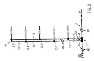
- FIG. 2 shows a schematic view of a loop 10, which is designed as a riser and two substantially parallel ring line sections comprises, which are formed as risers substantially parallel to each other and provided, for example, in a supply shaft of a building represented.
- Each of the ring line sections 11, 12 has a plurality of terminals 13 for consumers, not shown, wherein between the consumers and the respective terminals 13 close to the terminals 13 shut-off valves 14 are provided.
- the ring line 10 is also in this embodiment of a connection fitting 3 of a supply line 1 and is connected via shut-off valves 5 at the respective inlet and outlet openings 3b, 3a.
- the terminals 13 are alternately formed on the portion 11 and the portion 12 in the height direction, respectively.
- the usual main flow in the supply line is indicated by an arrow H.
- the circulation begins at the Ausfädelö réelle 3a and via the pipe sections 12, 11 leads to the threading 3b.
- the withdrawn water is almost predominantly supplied via the discharge opening 3a.
- at least the main part of the flow is supplied via the threading opening 3b.
- a measuring point M2 is shown as an alternative to the measuring point M1. Also there, temperature and / or flow rate can be measured and a central control device, which acts on the loop pump 60 and the circulation pump 61, are supplied.
- FIG. 2 embodiment shown represents a cold water system. A circulation pump is missing.
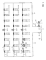
- FIG. 3 shows a further embodiment of a chilled water system with a main line 20, which opens at a distributor 21. From there go through the interposition of valves 22, 23 riser strands 24, 25 from.
- the valve 22 is a manually operated valve for shutting off the riser string 24;
- the valve 23 is a motor-operated valve for shutting off the riser string 25 and for actuating the flushing operation in conjunction with a motor-controlled flushing valve 26, whose function will be discussed later.
- each of the floor strands 27.1 to 27.3 is a motor-driven shut-off valve 28.1 to 28.3.
- the respective ring lines 2 are shown only with their associated shut-off valves 5, wherein the representation of the consumer was dispensed with these ring lines 2. It may be assumed that each of the ring lines 2 leads to a wet room in a hotel or a hospital with several cold water consumers.
- the floor strands 27.1 and 27.3 communicate with the two riser strands 24 and 25, whereby a ring line is formed, which opens into the manifold 21.
- a branch 29 which leads to a purge line 30 with a smaller nominal diameter, which can be opened and closed via the motor-driven flush valve 26 ,
- This purge line 30 opens into a sewer system.
- the respective motor-driven shut-off valves 28 are open.
- a consumer is opened on the ring main 2.1.1
- the supply of this consumer with service water takes place essentially via the riser 24.
- a consumer associated with the ring 2.1.8 open consumer the supply of hot water via the riser pipe 25.
- a consumer assigned to the central loop lines 2.1.4 or 2.1.5 is to remove water used, it flows almost equally through the riser strands 24 and 25.
- the corresponding ratio of the individual water flows changes with increasing distance from the corresponding riser strands.
- the majority of the service water is supplied via the riser pipe 24, whereas a small portion of the volume flow from the riser pipe 25 is fed.
- the measuring points M1 and M2 can optionally be provided. Also, the arrangement of the loop pump 60 and the measuring point MR can be exchanged with each other.
- Motor-controllable valves 36 are located at the upper end of the three left-hand strands 31.1 to 31.3. These valves 36 are provided between the individual strands 31.1 to 31.3 and the distribution line 34, whose distal end is connected to the last strand 31.4 a flow falling in the vertical direction leads and is connected at its end with a likewise controllable, ie motor-operated flushing valve 37, which leads to a discharge point.
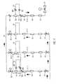
- FIG. 4 provided ring lines 10 has a ring line pump 60.
- a measuring point MR is further provided in each individual ring line 10 in each individual ring line 10.
- one measuring point M1 for example the threading opening 3a, can be arranged upstream in the flow direction of the strand 31.
Landscapes
- Engineering & Computer Science (AREA)
- Health & Medical Sciences (AREA)
- Life Sciences & Earth Sciences (AREA)
- Hydrology & Water Resources (AREA)
- Public Health (AREA)
- Water Supply & Treatment (AREA)
- Physics & Mathematics (AREA)
- Thermal Sciences (AREA)
- Chemical & Material Sciences (AREA)
- Combustion & Propulsion (AREA)
- Mechanical Engineering (AREA)
- General Engineering & Computer Science (AREA)
- Domestic Plumbing Installations (AREA)
- Devices For Dispensing Beverages (AREA)
Applications Claiming Priority (1)
| Application Number | Priority Date | Filing Date | Title |
|---|---|---|---|
| DE202010003376U DE202010003376U1 (de) | 2010-03-09 | 2010-03-09 | Trink- und Brauchwassersystem |
Publications (3)
| Publication Number | Publication Date |
|---|---|
| EP2365141A2 true EP2365141A2 (fr) | 2011-09-14 |
| EP2365141A3 EP2365141A3 (fr) | 2017-01-11 |
| EP2365141B1 EP2365141B1 (fr) | 2020-07-15 |
Family
ID=44168084
Family Applications (1)
| Application Number | Title | Priority Date | Filing Date |
|---|---|---|---|
| EP11001956.9A Active EP2365141B1 (fr) | 2010-03-09 | 2011-03-09 | Système d'eau sanitaire |
Country Status (2)
| Country | Link |
|---|---|
| EP (1) | EP2365141B1 (fr) |
| DE (1) | DE202010003376U1 (fr) |
Cited By (9)
| Publication number | Priority date | Publication date | Assignee | Title |
|---|---|---|---|---|
| EP2845956A1 (fr) * | 2013-09-04 | 2015-03-11 | I.C.B. Innovations-Center-Bad GmbH & Co. KG | Système d'installation d'eau potable pour bâtiment et procédé de vidange partielle d'un système d'installation d'eau potable |
| WO2017046109A1 (fr) * | 2015-09-18 | 2017-03-23 | Koninklijke Philips N.V. | Dispositif de surveillance destiné à la surveillance du comportement d'un sujet |
| WO2017134151A1 (fr) * | 2016-02-02 | 2017-08-10 | Equitherm Limited | Systèmes d'eau |
| EP3598009A1 (fr) * | 2018-07-18 | 2020-01-22 | R. Nussbaum AG | Distribution de l'eau |
| EP3660234A1 (fr) * | 2018-11-30 | 2020-06-03 | Gebr. Kemper GmbH + Co. KG Metallwerke | Système d'eau potable et d'eau sanitaire |
| EP3690151A1 (fr) * | 2019-01-31 | 2020-08-05 | Gebr. Kemper GmbH + Co. KG Metallwerke | Système d'eau potable et d'eau sanitaire et son procédé de rinçage |
| EP3957798A1 (fr) * | 2020-08-21 | 2022-02-23 | Wilo Se | Procédé de fonctionnement et/ou de surveillance d'une circulation d'eau |
| EP3951271A3 (fr) * | 2020-07-15 | 2022-04-27 | Gebr. Kemper GmbH + Co. KG | Système d'eau potable et d'eau sanitaire |
| EP4056768A1 (fr) | 2021-03-11 | 2022-09-14 | Gebr. Kemper GmbH + Co. KG | Installation d'eau potable |
Families Citing this family (2)
| Publication number | Priority date | Publication date | Assignee | Title |
|---|---|---|---|---|
| DE202012013037U1 (de) * | 2012-03-17 | 2014-09-08 | Norbert Windorfer | Trinkwasserleitungsanlage |
| DE202020103873U1 (de) | 2020-07-03 | 2021-10-07 | Gebr. Kemper Gmbh + Co. Kg | Vorrichtung zur Volumenstrommessung |
Citations (3)
| Publication number | Priority date | Publication date | Assignee | Title |
|---|---|---|---|---|
| DE102006017807A1 (de) | 2006-04-13 | 2007-10-18 | Gebr. Kemper Gmbh & Co. Kg Metallwerke | Trink- und Brauchwassersystem sowie Verfahren zum Betrieb eines solchen Systems |
| DE202007009832U1 (de) | 2007-07-12 | 2008-11-13 | Gebr. Kemper Gmbh & Co. Kg Metallwerke | Anschlussarmatur |
| EP2098645A1 (fr) | 2008-03-04 | 2009-09-09 | Gebr. Kemper GmbH + Co. KG Metallwerke | Système de boisson et d'eau sanitaire |
Family Cites Families (8)
| Publication number | Priority date | Publication date | Assignee | Title |
|---|---|---|---|---|
| DE3619217A1 (de) * | 1986-06-07 | 1987-12-10 | Vortex Gmbh Dt | Vorrichtung zur regelung der zirkulation in einem temperaturbeaufschlagten, entnahmestellen aufweisenden medienkreislauf |
| DE3916195C2 (de) * | 1989-01-25 | 1998-11-05 | Bernhard Miller | Wasserversorgungsanlage |
| DE9219121U1 (de) * | 1992-02-27 | 1998-03-12 | Sandler Energietechnik GmbH & Co. KG, 87600 Kaufbeuren | Regelungsvorrichtung für die Entnahmetemperatur von Brauchwasser mit Trinkwasserqualität |
| DE10008427A1 (de) * | 2000-02-23 | 2001-08-30 | Johann Wilfer | Umwälzinjektor für zentrale Warmwasser-Versorgungsanlagen |
| DE10118250A1 (de) * | 2000-04-13 | 2002-01-10 | Heinz Grueterich | Vorrichtung zur automatischen Warmwasserzirkulation |
| DE10061971A1 (de) * | 2000-12-13 | 2002-06-20 | Holger Raese | Steuereinrichtung für Warmwasserzirkulationspumpen |
| DE202008004421U1 (de) * | 2008-04-01 | 2008-07-03 | Kesap Kessel- Und Apparatebau Gmbh | Vorrichtung zum Erwärmen von Trinkwasser |
| DE202009001030U1 (de) * | 2009-01-27 | 2010-06-24 | Gebr. Kemper Gmbh & Co. Kg Metallwerke | Trink- oder Brauchwassersystem |
-
2010
- 2010-03-09 DE DE202010003376U patent/DE202010003376U1/de not_active Expired - Lifetime
-
2011
- 2011-03-09 EP EP11001956.9A patent/EP2365141B1/fr active Active
Patent Citations (3)
| Publication number | Priority date | Publication date | Assignee | Title |
|---|---|---|---|---|
| DE102006017807A1 (de) | 2006-04-13 | 2007-10-18 | Gebr. Kemper Gmbh & Co. Kg Metallwerke | Trink- und Brauchwassersystem sowie Verfahren zum Betrieb eines solchen Systems |
| DE202007009832U1 (de) | 2007-07-12 | 2008-11-13 | Gebr. Kemper Gmbh & Co. Kg Metallwerke | Anschlussarmatur |
| EP2098645A1 (fr) | 2008-03-04 | 2009-09-09 | Gebr. Kemper GmbH + Co. KG Metallwerke | Système de boisson et d'eau sanitaire |
Cited By (13)
| Publication number | Priority date | Publication date | Assignee | Title |
|---|---|---|---|---|
| EP2845956A1 (fr) * | 2013-09-04 | 2015-03-11 | I.C.B. Innovations-Center-Bad GmbH & Co. KG | Système d'installation d'eau potable pour bâtiment et procédé de vidange partielle d'un système d'installation d'eau potable |
| WO2017046109A1 (fr) * | 2015-09-18 | 2017-03-23 | Koninklijke Philips N.V. | Dispositif de surveillance destiné à la surveillance du comportement d'un sujet |
| US10900669B2 (en) | 2016-02-02 | 2021-01-26 | Equitherm Limited | Water systems |
| WO2017134151A1 (fr) * | 2016-02-02 | 2017-08-10 | Equitherm Limited | Systèmes d'eau |
| EP3598009A1 (fr) * | 2018-07-18 | 2020-01-22 | R. Nussbaum AG | Distribution de l'eau |
| EP3660234A1 (fr) * | 2018-11-30 | 2020-06-03 | Gebr. Kemper GmbH + Co. KG Metallwerke | Système d'eau potable et d'eau sanitaire |
| EP3690151A1 (fr) * | 2019-01-31 | 2020-08-05 | Gebr. Kemper GmbH + Co. KG Metallwerke | Système d'eau potable et d'eau sanitaire et son procédé de rinçage |
| US11225780B2 (en) | 2019-01-31 | 2022-01-18 | Gebr. Kemper Gmbh + Co., Kg Metallwerke | Drinking and service water system and method for flushing same |
| EP3951271A3 (fr) * | 2020-07-15 | 2022-04-27 | Gebr. Kemper GmbH + Co. KG | Système d'eau potable et d'eau sanitaire |
| EP3957798A1 (fr) * | 2020-08-21 | 2022-02-23 | Wilo Se | Procédé de fonctionnement et/ou de surveillance d'une circulation d'eau |
| EP4502474A3 (fr) * | 2020-08-21 | 2025-04-16 | Wilo Se | Procédé de fonctionnement et/ou de surveillance d'une circulation d'eau |
| EP4502475A3 (fr) * | 2020-08-21 | 2025-04-23 | Wilo Se | Procédé de fonctionnement et/ou de surveillance d'une circulation d'eau |
| EP4056768A1 (fr) | 2021-03-11 | 2022-09-14 | Gebr. Kemper GmbH + Co. KG | Installation d'eau potable |
Also Published As
| Publication number | Publication date |
|---|---|
| DE202010003376U1 (de) | 2011-08-01 |
| EP2365141B1 (fr) | 2020-07-15 |
| EP2365141A3 (fr) | 2017-01-11 |
Similar Documents
| Publication | Publication Date | Title |
|---|---|---|
| EP2365141A2 (fr) | Système d'eau sanitaire | |
| EP2098645A1 (fr) | Système de boisson et d'eau sanitaire | |
| EP1887150B1 (fr) | Système d'eau potable et usée tout comme son procédé de fonctionnement | |
| EP3037591B1 (fr) | Systeme de boisson ou d'eau sanitaire | |
| WO2014029699A1 (fr) | Dispositif de protection contre les fuites | |
| EP2466019A2 (fr) | Système d'alimentation en eau potable d'un bâtiment, procédé de fonctionnement de celui-ci et dispositif de commande de celui-ci | |
| DE202013102154U1 (de) | Anordnung zur Durchführung einer Hygienespülung in einer Wasserinstallation | |
| EP2993271B1 (fr) | Dispositif de commande et système d'eau potable et/ou sanitaire ayant un tel dispositif de commande | |
| EP1431466A2 (fr) | Ensemble compact de tuyauteries et robinetteries d'alimentation en eau froide et/ou en eau de chauffage et/ou en eau potable chaude | |
| EP2210985B1 (fr) | Dispositif de raccordement | |
| EP3670765B1 (fr) | Alimentation de chauffe-eau | |
| DE202007010982U1 (de) | Rohrsystem zur Verteilung von Trinkwasser in Gebäuden | |
| EP3957860B1 (fr) | Module compact pour une circulation d'eau | |
| EP2885467B2 (fr) | Installation d'eau potable avec détection de fuite | |
| DE102005024252A1 (de) | Leitungsanordnung, sowie Rohrleitungsanschlussstück und Rohrleitungsabschnitt | |
| DE102019135548A1 (de) | Trinkwasserleitungsmodul zur Trinkwasserzirkulation bei geschlossenen Zapfstellen | |
| DE102019111486A1 (de) | Trinkwasser-Leitungsmodul zur Trinkwasserzirkulation bei geschlossenen Zapfstellen | |
| EP3495745B1 (fr) | Régulateur de pression différentielle auto-régulant pour un système d' eau potable et système d'eau potable doté d'un tel régulateur de pression différentiel auto-régulant | |
| DE102021130510A1 (de) | Trinkwasserleitungsmodul | |
| DE102024100027A1 (de) | Bereitstellungsverfahren zur Bereitstellung von Trinkwasser, Trinkwasserversorgungsanordnung sowie Warmwasser- und Spülschalteinheit | |
| DE202023105233U1 (de) | Trink- und Brauchwassersystem und Absperrventil dafür | |
| WO2025119433A2 (fr) | Procédé de mise à disposition d'eau potable, dispositif d'alimentation en eau potable et unité de commutation d'eau chaude et de rinçage | |
| DE102024118541A1 (de) | Trinkwasserleitungssystem zur Versorgung von Trinkwasserverbrauchern einer Wohneinheit | |
| DE102015015649A1 (de) | Leitungsspülvorrichtung und leitungsspülsystem | |
| DE102021207775A1 (de) | Haushaltsgerät zur Ausgabe von Flüssigkeit mit einem gekoppelten Wasserausgabe-Spülmodus, sowie Verfahren |
Legal Events
| Date | Code | Title | Description |
|---|---|---|---|
| PUAI | Public reference made under article 153(3) epc to a published international application that has entered the european phase |
Free format text: ORIGINAL CODE: 0009012 |
|
| AK | Designated contracting states |
Kind code of ref document: A2 Designated state(s): AL AT BE BG CH CY CZ DE DK EE ES FI FR GB GR HR HU IE IS IT LI LT LU LV MC MK MT NL NO PL PT RO RS SE SI SK SM TR |
|
| AX | Request for extension of the european patent |
Extension state: BA ME |
|
| PUAL | Search report despatched |
Free format text: ORIGINAL CODE: 0009013 |
|
| AK | Designated contracting states |
Kind code of ref document: A3 Designated state(s): AL AT BE BG CH CY CZ DE DK EE ES FI FR GB GR HR HU IE IS IT LI LT LU LV MC MK MT NL NO PL PT RO RS SE SI SK SM TR |
|
| AX | Request for extension of the european patent |
Extension state: BA ME |
|
| RIC1 | Information provided on ipc code assigned before grant |
Ipc: E03B 7/04 20060101AFI20161206BHEP Ipc: F24D 17/00 20060101ALI20161206BHEP |
|
| STAA | Information on the status of an ep patent application or granted ep patent |
Free format text: STATUS: REQUEST FOR EXAMINATION WAS MADE |
|
| 17P | Request for examination filed |
Effective date: 20170208 |
|
| RBV | Designated contracting states (corrected) |
Designated state(s): AL AT BE BG CH CY CZ DE DK EE ES FI FR GB GR HR HU IE IS IT LI LT LU LV MC MK MT NL NO PL PT RO RS SE SI SK SM TR |
|
| STAA | Information on the status of an ep patent application or granted ep patent |
Free format text: STATUS: EXAMINATION IS IN PROGRESS |
|
| 17Q | First examination report despatched |
Effective date: 20190430 |
|
| GRAP | Despatch of communication of intention to grant a patent |
Free format text: ORIGINAL CODE: EPIDOSNIGR1 |
|
| STAA | Information on the status of an ep patent application or granted ep patent |
Free format text: STATUS: GRANT OF PATENT IS INTENDED |
|
| INTG | Intention to grant announced |
Effective date: 20200506 |
|
| GRAS | Grant fee paid |
Free format text: ORIGINAL CODE: EPIDOSNIGR3 |
|
| GRAA | (expected) grant |
Free format text: ORIGINAL CODE: 0009210 |
|
| STAA | Information on the status of an ep patent application or granted ep patent |
Free format text: STATUS: THE PATENT HAS BEEN GRANTED |
|
| AK | Designated contracting states |
Kind code of ref document: B1 Designated state(s): AL AT BE BG CH CY CZ DE DK EE ES FI FR GB GR HR HU IE IS IT LI LT LU LV MC MK MT NL NO PL PT RO RS SE SI SK SM TR |
|
| REG | Reference to a national code |
Ref country code: CH Ref legal event code: EP Ref country code: GB Ref legal event code: FG4D Free format text: NOT ENGLISH |
|
| REG | Reference to a national code |
Ref country code: CH Ref legal event code: NV Representative=s name: BOVARD AG PATENT- UND MARKENANWAELTE, CH |
|
| REG | Reference to a national code |
Ref country code: IE Ref legal event code: FG4D Free format text: LANGUAGE OF EP DOCUMENT: GERMAN |
|
| REG | Reference to a national code |
Ref country code: DE Ref legal event code: R096 Ref document number: 502011016787 Country of ref document: DE |
|
| REG | Reference to a national code |
Ref country code: AT Ref legal event code: REF Ref document number: 1291178 Country of ref document: AT Kind code of ref document: T Effective date: 20200815 |
|
| REG | Reference to a national code |
Ref country code: LT Ref legal event code: MG4D |
|
| REG | Reference to a national code |
Ref country code: NL Ref legal event code: MP Effective date: 20200715 |
|
| PG25 | Lapsed in a contracting state [announced via postgrant information from national office to epo] |
Ref country code: HR Free format text: LAPSE BECAUSE OF FAILURE TO SUBMIT A TRANSLATION OF THE DESCRIPTION OR TO PAY THE FEE WITHIN THE PRESCRIBED TIME-LIMIT Effective date: 20200715 Ref country code: LT Free format text: LAPSE BECAUSE OF FAILURE TO SUBMIT A TRANSLATION OF THE DESCRIPTION OR TO PAY THE FEE WITHIN THE PRESCRIBED TIME-LIMIT Effective date: 20200715 Ref country code: BG Free format text: LAPSE BECAUSE OF FAILURE TO SUBMIT A TRANSLATION OF THE DESCRIPTION OR TO PAY THE FEE WITHIN THE PRESCRIBED TIME-LIMIT Effective date: 20201015 Ref country code: SE Free format text: LAPSE BECAUSE OF FAILURE TO SUBMIT A TRANSLATION OF THE DESCRIPTION OR TO PAY THE FEE WITHIN THE PRESCRIBED TIME-LIMIT Effective date: 20200715 Ref country code: PT Free format text: LAPSE BECAUSE OF FAILURE TO SUBMIT A TRANSLATION OF THE DESCRIPTION OR TO PAY THE FEE WITHIN THE PRESCRIBED TIME-LIMIT Effective date: 20201116 Ref country code: ES Free format text: LAPSE BECAUSE OF FAILURE TO SUBMIT A TRANSLATION OF THE DESCRIPTION OR TO PAY THE FEE WITHIN THE PRESCRIBED TIME-LIMIT Effective date: 20200715 Ref country code: FI Free format text: LAPSE BECAUSE OF FAILURE TO SUBMIT A TRANSLATION OF THE DESCRIPTION OR TO PAY THE FEE WITHIN THE PRESCRIBED TIME-LIMIT Effective date: 20200715 Ref country code: GR Free format text: LAPSE BECAUSE OF FAILURE TO SUBMIT A TRANSLATION OF THE DESCRIPTION OR TO PAY THE FEE WITHIN THE PRESCRIBED TIME-LIMIT Effective date: 20201016 Ref country code: NO Free format text: LAPSE BECAUSE OF FAILURE TO SUBMIT A TRANSLATION OF THE DESCRIPTION OR TO PAY THE FEE WITHIN THE PRESCRIBED TIME-LIMIT Effective date: 20201015 |
|
| PG25 | Lapsed in a contracting state [announced via postgrant information from national office to epo] |
Ref country code: LV Free format text: LAPSE BECAUSE OF FAILURE TO SUBMIT A TRANSLATION OF THE DESCRIPTION OR TO PAY THE FEE WITHIN THE PRESCRIBED TIME-LIMIT Effective date: 20200715 Ref country code: RS Free format text: LAPSE BECAUSE OF FAILURE TO SUBMIT A TRANSLATION OF THE DESCRIPTION OR TO PAY THE FEE WITHIN THE PRESCRIBED TIME-LIMIT Effective date: 20200715 Ref country code: PL Free format text: LAPSE BECAUSE OF FAILURE TO SUBMIT A TRANSLATION OF THE DESCRIPTION OR TO PAY THE FEE WITHIN THE PRESCRIBED TIME-LIMIT Effective date: 20200715 Ref country code: IS Free format text: LAPSE BECAUSE OF FAILURE TO SUBMIT A TRANSLATION OF THE DESCRIPTION OR TO PAY THE FEE WITHIN THE PRESCRIBED TIME-LIMIT Effective date: 20201115 |
|
| PG25 | Lapsed in a contracting state [announced via postgrant information from national office to epo] |
Ref country code: NL Free format text: LAPSE BECAUSE OF FAILURE TO SUBMIT A TRANSLATION OF THE DESCRIPTION OR TO PAY THE FEE WITHIN THE PRESCRIBED TIME-LIMIT Effective date: 20200715 |
|
| REG | Reference to a national code |
Ref country code: DE Ref legal event code: R097 Ref document number: 502011016787 Country of ref document: DE |
|
| PG25 | Lapsed in a contracting state [announced via postgrant information from national office to epo] |
Ref country code: RO Free format text: LAPSE BECAUSE OF FAILURE TO SUBMIT A TRANSLATION OF THE DESCRIPTION OR TO PAY THE FEE WITHIN THE PRESCRIBED TIME-LIMIT Effective date: 20200715 Ref country code: SM Free format text: LAPSE BECAUSE OF FAILURE TO SUBMIT A TRANSLATION OF THE DESCRIPTION OR TO PAY THE FEE WITHIN THE PRESCRIBED TIME-LIMIT Effective date: 20200715 Ref country code: DK Free format text: LAPSE BECAUSE OF FAILURE TO SUBMIT A TRANSLATION OF THE DESCRIPTION OR TO PAY THE FEE WITHIN THE PRESCRIBED TIME-LIMIT Effective date: 20200715 Ref country code: EE Free format text: LAPSE BECAUSE OF FAILURE TO SUBMIT A TRANSLATION OF THE DESCRIPTION OR TO PAY THE FEE WITHIN THE PRESCRIBED TIME-LIMIT Effective date: 20200715 Ref country code: CZ Free format text: LAPSE BECAUSE OF FAILURE TO SUBMIT A TRANSLATION OF THE DESCRIPTION OR TO PAY THE FEE WITHIN THE PRESCRIBED TIME-LIMIT Effective date: 20200715 Ref country code: IT Free format text: LAPSE BECAUSE OF FAILURE TO SUBMIT A TRANSLATION OF THE DESCRIPTION OR TO PAY THE FEE WITHIN THE PRESCRIBED TIME-LIMIT Effective date: 20200715 |
|
| PLBE | No opposition filed within time limit |
Free format text: ORIGINAL CODE: 0009261 |
|
| STAA | Information on the status of an ep patent application or granted ep patent |
Free format text: STATUS: NO OPPOSITION FILED WITHIN TIME LIMIT |
|
| PG25 | Lapsed in a contracting state [announced via postgrant information from national office to epo] |
Ref country code: AL Free format text: LAPSE BECAUSE OF FAILURE TO SUBMIT A TRANSLATION OF THE DESCRIPTION OR TO PAY THE FEE WITHIN THE PRESCRIBED TIME-LIMIT Effective date: 20200715 |
|
| 26N | No opposition filed |
Effective date: 20210416 |
|
| PG25 | Lapsed in a contracting state [announced via postgrant information from national office to epo] |
Ref country code: SK Free format text: LAPSE BECAUSE OF FAILURE TO SUBMIT A TRANSLATION OF THE DESCRIPTION OR TO PAY THE FEE WITHIN THE PRESCRIBED TIME-LIMIT Effective date: 20200715 |
|
| PG25 | Lapsed in a contracting state [announced via postgrant information from national office to epo] |
Ref country code: SI Free format text: LAPSE BECAUSE OF FAILURE TO SUBMIT A TRANSLATION OF THE DESCRIPTION OR TO PAY THE FEE WITHIN THE PRESCRIBED TIME-LIMIT Effective date: 20200715 |
|
| PG25 | Lapsed in a contracting state [announced via postgrant information from national office to epo] |
Ref country code: MC Free format text: LAPSE BECAUSE OF FAILURE TO SUBMIT A TRANSLATION OF THE DESCRIPTION OR TO PAY THE FEE WITHIN THE PRESCRIBED TIME-LIMIT Effective date: 20200715 |
|
| GBPC | Gb: european patent ceased through non-payment of renewal fee |
Effective date: 20210309 |
|
| REG | Reference to a national code |
Ref country code: BE Ref legal event code: MM Effective date: 20210331 |
|
| PG25 | Lapsed in a contracting state [announced via postgrant information from national office to epo] |
Ref country code: IE Free format text: LAPSE BECAUSE OF NON-PAYMENT OF DUE FEES Effective date: 20210309 Ref country code: FR Free format text: LAPSE BECAUSE OF NON-PAYMENT OF DUE FEES Effective date: 20210331 Ref country code: GB Free format text: LAPSE BECAUSE OF NON-PAYMENT OF DUE FEES Effective date: 20210309 Ref country code: LU Free format text: LAPSE BECAUSE OF NON-PAYMENT OF DUE FEES Effective date: 20210309 |
|
| PG25 | Lapsed in a contracting state [announced via postgrant information from national office to epo] |
Ref country code: BE Free format text: LAPSE BECAUSE OF NON-PAYMENT OF DUE FEES Effective date: 20210331 |
|
| PG25 | Lapsed in a contracting state [announced via postgrant information from national office to epo] |
Ref country code: HU Free format text: LAPSE BECAUSE OF FAILURE TO SUBMIT A TRANSLATION OF THE DESCRIPTION OR TO PAY THE FEE WITHIN THE PRESCRIBED TIME-LIMIT; INVALID AB INITIO Effective date: 20110309 Ref country code: CY Free format text: LAPSE BECAUSE OF FAILURE TO SUBMIT A TRANSLATION OF THE DESCRIPTION OR TO PAY THE FEE WITHIN THE PRESCRIBED TIME-LIMIT Effective date: 20200715 |
|
| P01 | Opt-out of the competence of the unified patent court (upc) registered |
Effective date: 20240304 |
|
| PGFP | Annual fee paid to national office [announced via postgrant information from national office to epo] |
Ref country code: AT Payment date: 20240319 Year of fee payment: 14 |
|
| PG25 | Lapsed in a contracting state [announced via postgrant information from national office to epo] |
Ref country code: MK Free format text: LAPSE BECAUSE OF FAILURE TO SUBMIT A TRANSLATION OF THE DESCRIPTION OR TO PAY THE FEE WITHIN THE PRESCRIBED TIME-LIMIT Effective date: 20200715 |
|
| PGFP | Annual fee paid to national office [announced via postgrant information from national office to epo] |
Ref country code: DE Payment date: 20240327 Year of fee payment: 14 |
|
| PG25 | Lapsed in a contracting state [announced via postgrant information from national office to epo] |
Ref country code: TR Free format text: LAPSE BECAUSE OF FAILURE TO SUBMIT A TRANSLATION OF THE DESCRIPTION OR TO PAY THE FEE WITHIN THE PRESCRIBED TIME-LIMIT Effective date: 20200715 |
|
| PGFP | Annual fee paid to national office [announced via postgrant information from national office to epo] |
Ref country code: CH Payment date: 20240401 Year of fee payment: 14 |
|
| PG25 | Lapsed in a contracting state [announced via postgrant information from national office to epo] |
Ref country code: MT Free format text: LAPSE BECAUSE OF FAILURE TO SUBMIT A TRANSLATION OF THE DESCRIPTION OR TO PAY THE FEE WITHIN THE PRESCRIBED TIME-LIMIT Effective date: 20200715 |
|
| REG | Reference to a national code |
Ref country code: DE Ref legal event code: R119 Ref document number: 502011016787 Country of ref document: DE |
|
| REG | Reference to a national code |
Ref country code: CH Ref legal event code: H13 Free format text: ST27 STATUS EVENT CODE: U-0-0-H10-H13 (AS PROVIDED BY THE NATIONAL OFFICE) Effective date: 20251023 |
|
| REG | Reference to a national code |
Ref country code: AT Ref legal event code: MM01 Ref document number: 1291178 Country of ref document: AT Kind code of ref document: T Effective date: 20250309 |
|
| PG25 | Lapsed in a contracting state [announced via postgrant information from national office to epo] |
Ref country code: DE Free format text: LAPSE BECAUSE OF NON-PAYMENT OF DUE FEES Effective date: 20251001 |
|
| PG25 | Lapsed in a contracting state [announced via postgrant information from national office to epo] |
Ref country code: AT Free format text: LAPSE BECAUSE OF NON-PAYMENT OF DUE FEES Effective date: 20250309 |
|
| PG25 | Lapsed in a contracting state [announced via postgrant information from national office to epo] |
Ref country code: CH Free format text: LAPSE BECAUSE OF NON-PAYMENT OF DUE FEES Effective date: 20250331 |