EP2365249B1 - Method for installing a chimney pipe for a heating assembly in a waste gas chimney and assembly set - Google Patents
Method for installing a chimney pipe for a heating assembly in a waste gas chimney and assembly set Download PDFInfo
- Publication number
- EP2365249B1 EP2365249B1 EP20100002366 EP10002366A EP2365249B1 EP 2365249 B1 EP2365249 B1 EP 2365249B1 EP 20100002366 EP20100002366 EP 20100002366 EP 10002366 A EP10002366 A EP 10002366A EP 2365249 B1 EP2365249 B1 EP 2365249B1
- Authority
- EP
- European Patent Office
- Prior art keywords
- chimney
- pipe
- waste gas
- connection
- chimney pipe
- Prior art date
- Legal status (The legal status is an assumption and is not a legal conclusion. Google has not performed a legal analysis and makes no representation as to the accuracy of the status listed.)
- Active
Links
- 238000010438 heat treatment Methods 0.000 title claims description 46
- 238000000034 method Methods 0.000 title claims description 29
- 239000002912 waste gas Substances 0.000 title claims 17
- 238000009434 installation Methods 0.000 claims description 15
- 229920003023 plastic Polymers 0.000 claims description 14
- 239000004033 plastic Substances 0.000 claims description 14
- 239000002184 metal Substances 0.000 claims description 10
- 239000000463 material Substances 0.000 claims description 5
- 238000003780 insertion Methods 0.000 claims description 2
- 230000037431 insertion Effects 0.000 claims description 2
- 239000007789 gas Substances 0.000 description 20
- 230000001681 protective effect Effects 0.000 description 17
- 239000000725 suspension Substances 0.000 description 5
- 239000002033 PVDF binder Substances 0.000 description 3
- UGFAIRIUMAVXCW-UHFFFAOYSA-N Carbon monoxide Chemical compound [O+]#[C-] UGFAIRIUMAVXCW-UHFFFAOYSA-N 0.000 description 2
- 238000013459 approach Methods 0.000 description 2
- 230000005494 condensation Effects 0.000 description 2
- 238000009833 condensation Methods 0.000 description 2
- 239000003546 flue gas Substances 0.000 description 2
- 239000006260 foam Substances 0.000 description 2
- 229920002981 polyvinylidene fluoride Polymers 0.000 description 2
- 238000012360 testing method Methods 0.000 description 2
- 229910000831 Steel Inorganic materials 0.000 description 1
- 230000009471 action Effects 0.000 description 1
- 239000011449 brick Substances 0.000 description 1
- 230000008878 coupling Effects 0.000 description 1
- 238000010168 coupling process Methods 0.000 description 1
- 238000005859 coupling reaction Methods 0.000 description 1
- 230000007423 decrease Effects 0.000 description 1
- 238000013461 design Methods 0.000 description 1
- 238000011161 development Methods 0.000 description 1
- 230000018109 developmental process Effects 0.000 description 1
- 239000013013 elastic material Substances 0.000 description 1
- 239000003517 fume Substances 0.000 description 1
- 238000007689 inspection Methods 0.000 description 1
- 239000000696 magnetic material Substances 0.000 description 1
- 230000008569 process Effects 0.000 description 1
- 230000007480 spreading Effects 0.000 description 1
- 229910001220 stainless steel Inorganic materials 0.000 description 1
- 239000010935 stainless steel Substances 0.000 description 1
- 239000010959 steel Substances 0.000 description 1
- 239000002918 waste heat Substances 0.000 description 1
Images

Classifications
-
- F—MECHANICAL ENGINEERING; LIGHTING; HEATING; WEAPONS; BLASTING
- F23—COMBUSTION APPARATUS; COMBUSTION PROCESSES
- F23J—REMOVAL OR TREATMENT OF COMBUSTION PRODUCTS OR COMBUSTION RESIDUES; FLUES
- F23J11/00—Devices for conducting smoke or fumes, e.g. flues
- F23J11/12—Smoke conduit systems for factories or large buildings
-
- F—MECHANICAL ENGINEERING; LIGHTING; HEATING; WEAPONS; BLASTING
- F23—COMBUSTION APPARATUS; COMBUSTION PROCESSES
- F23J—REMOVAL OR TREATMENT OF COMBUSTION PRODUCTS OR COMBUSTION RESIDUES; FLUES
- F23J2211/00—Flue gas duct systems
- F23J2211/40—Chimney with internal flue pipe system
Definitions
- the invention relates to a method for installing a chimney pipe for a heating system in an exhaust stack.
- a method is for example from FR 2 818 965 known.
- multi-storey buildings for example residential buildings
- have an exhaust stack which serves for the discharge or discharge of the exhaust gases of a variety of heating systems.
- the heating systems can be installed in particular in apartments or residential units on different floors and be coupled via connection points with the exhaust stack such that the exhaust gases are introduced into the exhaust stack via the connection points.
- the present invention seeks to develop a method for installing a chimney pipe for a heating system in an exhaust stack, which allows a simple, subsequent installation of a chimney pipe in an existing flue without this essential structural changes in the exhaust stack or high investment costs are required or the operation of older, conventional heating systems is disturbed.
- This object is achieved by a method having the features of claim 1.
- the at least one auxiliary means comprises a first part which is introduced from the side of the connection region into the exhaust gas chimney, from the chimney end a second part of the first auxiliary means into the exhaust gas Is introduced exhaust stack and that the two ends in the exhaust stack contact each other, such that between the two parts made a mechanical load-bearing connection becomes.
- the first part has at least one flexible part, in particular in the form of an extension rod and at least on the side at which the connection is made with the second part, a first magnetically effective Having area in the form of a metal plate and that the second part on the side facing the first part has a second magnetically active area, such that attract the two magnetically active areas.
- the two respective end portions of the first and second parts can be positioned relative to one another in a relatively simple manner, since in the presence of a certain magnetic attraction the two parts approach and contact one another.
- the handling of the two parts of the first auxiliary element is facilitated if the first part is in the form of an extension rod, if the second part has at least one flexible element in the form of a cord or a band, if the end of the cord inserted into the fume hood or the band is provided with a ballast or the band tightening ballast element, and when the ballast element or the ballast element facing the end has a magnetic element.
- the required length for the chimney pipe can be determined when a tape measure is used as a band and, if the required length of the chimney pipe is determined after establishing the connection between the chimney end and the connection area by means of the tape measure.
- the read Value of the tape measure an additional length is added as a security, so that any existing bends or bends, which are bridged by the tape measure on the shortest path, can be easily bridged by the chimney pipe having a certain diameter also.
- the method additionally comprises attaching at least one adapter plate to the side of the chimney end and attaching the chimney pipe to the adapter plate.
- the chimney pipe is at least partially flexible.
- the area of the protective element can be bridged or passed through relatively easily.
- the chimney pipe consists at least partially of plastic, in particular of PVDF.
- the invention also advantageously comprises in addition the method step of checking the tightness of the chimney pipe after its installation between the chimney end and the connection point.
- This will damage any damage that may occur during installation of the chimney pipe, e.g. could be detected by contact or by contact with sharp edges or the like, reliably detected and thus prevents commissioning.
- the check is carried out by means of a positive pressure source, wherein the two ends of the chimney pipe are closed and the chimney pipe is exposed to an overpressure. If damage has been set in the wall of the chimney pipe during assembly or installation of the chimney pipe, such damage can be easily detected or noticed by a drop in pressure.
- each of the connection regions 27 is assigned a protective element 30.
- the perpendicular to the plane of the Fig. 1 over the entire exhaust duct 20 extending protective element 30 is preferably designed as a rampart, has a wall portion 31 which extends approximately parallel to the wall 26 of the exhaust duct 20 and extends from the respective floor 11 to 16 on the floor 11 to 16 also upwards ,
- protective element 30 is an increased fire safety in conventional heating systems 19 causes or achieved.
- An exhaust gas fireplace 1 described so far with the protective elements 30 is referred to in France as a so-called "shunt fireplace".
- a chimney end 34 in particular the outlet of the exhaust chimney 1 is referred to the environment.
- the respective ends 33 of the three chimney pipes 25 are arranged in receptacles 35, 36 of an adapter plate 37a, 37b made of steel or plastic, the receptacles 35, 36 being designed in particular as through-holes. Further, the two adapter plates 37a, 37b placed on the chimney end 34 and preferably connected to the chimney end 34 fixed.
- two adapter plates 37a, 37b are provided which cover a total of only a portion of the opening cross-section of the exhaust duct 20, so over the non-covered by the adapter plates 37a, 37b cross-section the exhaust gas chimney 20, the exhaust gases of the (conventional) heating systems 21 can be discharged to the environment.
- each of the chimney pipes 25 is assigned to a special adapter plate 37a, 37b.
- a special adapter plate 37a, 37b it is provided that between one and three adapter plates 37a, 37b, 37c are provided.
- each of the adapter plates 37a, 37b, 37c serves to accommodate a maximum of two chimney tubes 25.
- the case is shown in which all six floors 11 to 16 are equipped with (more modern) heating systems 22.
- all three adapter plates 37a, 37b and 37c are used. It is essential here that the adapter plate 37a, which has the smallest distance to the wall 26 of the exhaust shaft 20, the two (upper) floors 15 and 16, the (middle) adapter plate 37b the two (middle) floors 13 and 14 and the farthest from the wall 26 remote adapter plate 37 c is assigned to the two (lower) floors 11 and 12.
- the corresponding adapter plate 37a to 37c used or installed.
- the available cross section of the exhaust duct 20 is optimally utilized for the guidance of the chimney pipes 25 and, in the case of a mixed operation with heating systems 21 and 22, the exhaust ducting of the heating systems 21 is optimized.
- the mounting kit 40 which allows a first aid 41 to provide a connection between the fireplace end 34 and the corresponding terminal portion 27.
- the first aid 41 has for this purpose a measuring tape 42, at one end of a ballast weight 43 is arranged.
- the mounting set 40 comprises a second part designed as a sheet metal plate 44 with rollers 45 and a flexible extension bar 46 with a length of about 3m, which manually (together with the metal plate 44) can be passed through the connection portion 27, wherein it As a result of its flexible extension rod 46 the shape of the protective element 30 adapts or this can happen by the sheet metal plate 44, for example, at the Wall 26 of the exhaust duct 20 or rolls along the opposite wall of the exhaust duct 20 along.
- a magnetic element 47 is additionally arranged on the end of the measuring tape 42 facing the ballast weight 43.
- the ballast weight 43 itself consists of magnetic material.
- connection between the chimney end 34 and the connection region 27 takes place according to the Fig. 5 in that the end of the measuring tape 42 assigned to the ballast weight 43 passes through the receptacle 35 and the measuring tape 42 is lowered in the direction of the protective element 30 of the floor 16.
- the metal plate 44 was spent in the direction of the end of the fireplace 34 via the connection area 27 of the floor 16.
- a mechanical connection between the magnetic element 47 or the measuring tape 42 and the metal plate 44 takes place due to the magnetic attraction.
- the sheet metal plate 44 can be pulled down with the end of the measuring tape 42 in the region of the connection region 27, so that the measuring tape 42 together with the ballast weight 43 passes through the connection region 27.
- the value for the length of the connection between the connection region 27 and the chimney end 34 or the adapter plate 37a assigned to the floor 16 is now read off at the chimney end 34 on the measuring tape 42, whereby the required length for the chimney pipe 25 can be determined.
- this determined value can be added an additional length, so as to ensure in each case a sufficient length of the chimney pipe 25 and to facilitate the subsequent assembly of the ends 32, 33 of the chimney pipe 25.
- the adapter element 52 which also serves to check the tightness of the chimney pipe 25, has a protective cone 53 and a cylindrically shaped receiving and expanding section 54.
- the diameter of the receiving and expanding portion 54 is preferably adjustable with the interposition of a 6-8 cm long foam tube 56 by means of a wedge 55, so that the with its inner circumference on the receiving and spreading portion 54 deferred until the cone 53 end 32 of the chimney pipe 25th mechanically fixed and sealed with the chimney pipe 25 is connectable.
- the chimney pipe 25 is preferably made of plastic, here in particular at least partially made of PVDF (polyvinylidene fluoride). In particular, it has at least one partial area, which is designed to be flexible, such that it can easily pass through the protective element 30 in the exhaust shaft 20. Preferably, the chimney pipe 25 is flexible over its entire length (flexible tube).
- PVDF polyvinylidene fluoride
- the chimney pipe 25 can be provided with fastening elements which make it possible to fix the chimney pipe 25 to the connection region 27.
- the other end 33 of the chimney pipe 25 may be located within the exhaust duct 20, being secured by the securing plate.
- the end 32 can be drawn relatively far into the connection region 27, in order to facilitate the assembly of the fastening elements (not shown) for the end 32 of the chimney pipe 25, without the chimney pipe 25 having to be specially extended for this purpose.
- the end 33 of the chimney pipe 25 is pulled upwards by the receptacle 35 and the cable 59 is connected to a spring balance 65, wherein previously the suspension ring 38 has been pushed onto the outer circumference of the chimney pipe 25.
- the second adapter element 57 may also be connected directly to the spring balance 65 become. Then, a defined tensile force is exerted on the second adapter element 57 by means of the spring balance 65.
- the chimney pipe 25 between the connection region 27 and the chimney end 34 or the adapter plate 37 a is stretched or its length minimized ( Figure 7 ). This is done in particular with regard to any elongation of the chimney pipe 25 during operation of the heating systems 21, 22 as a result of thermal expansion.
Landscapes
- Engineering & Computer Science (AREA)
- Architecture (AREA)
- Mechanical Engineering (AREA)
- General Engineering & Computer Science (AREA)
- Chimneys And Flues (AREA)
Description
Die Erfindung betrifft ein Verfahren zur Installation eines Kaminrohrs für eine Heizungsanlage in einem Abgaskamin. Ein solches Verfahren ist zum Beispiel aus dem
Insbesondere mehrgeschossige Gebäude, zum Beispiel Wohngebäude, weisen einen Abgaskamin auf, der zur Ableitung bzw. zum Abführen der Abgase einer Vielzahl von Heizungsanlagen dient. Hierbei können die Heizungsanlagen insbesondere in Wohnungen oder Wohneinheiten auf unterschiedlichen Stockwerken installiert sein und über Anschlussstellen mit dem Abgaskamin derart gekoppelt sein, dass über die Anschlussstellen die Abgase in den Abgaskamin eingeleitet werden.In particular, multi-storey buildings, for example residential buildings, have an exhaust stack, which serves for the discharge or discharge of the exhaust gases of a variety of heating systems. Here, the heating systems can be installed in particular in apartments or residential units on different floors and be coupled via connection points with the exhaust stack such that the exhaust gases are introduced into the exhaust stack via the connection points.
Während konventionelle bzw. ältere Heizungsanlagen, die z.B. mit Gas betrieben werden, relativ hohe Abgastemperaturen im Bereich von beispielsweise 160°C aufweisen, weisen moderne Heizungsanlagen, die insbesondere als Niedertemperatur- bzw. Kondensationsheizung ausgebildet sind, eine niedrigere Abgastemperatur auf. Um derartige, relativ moderne und energiesparende Heizungsanlagen betreiben zu können, hat die Anwenderin unter dem Markennamen "TECHNAFLON®" Kunststoff-Kaminrohre entwickelt und auf den Markt gebracht, welche sich insbesondere auch sehr gut zur Verwendung bei den angesprochenen Niedrigenergieheizanlagen eignen. Insbesondere bestehen derartige Kunststoff-Kaminrohre aus dem Werkstoff PVDF, wobei dieses zähe, UV-und hochtemperaturbeständige Material nicht nur Abgastemperaturen von etwa 160°C ermöglicht, auch ist dieser Werkstoff beständig gegen insbesondere in Kondensations- bzw. Nasskaminen auftretendes, aggressives Kondensat. Nicht zuletzt erreicht das Material die Brandklasse V0, sodass sich damit gefertigte, bekannte Kunststoff-Kaminrohre als Alternative zu Edelstahlrohren etablieren konnten.While conventional or older heating systems that are operated with gas, for example, have relatively high exhaust gas temperatures in the range of for example 160 ° C, have modern heating systems, which are designed in particular as low-temperature or condensation heating, a lower exhaust gas temperature. In order to operate such, relatively modern and energy-saving heating systems, the user has developed under the brand name "TECHNAFLON®" plastic chimney pipes and brought to the market, which are particularly well suited for use in the mentioned low-energy heating. In particular, such plastic chimney pipes made of PVDF material, said tough, UV and high temperature resistant material not only allows exhaust gas temperatures of about 160 ° C, and this material is resistant to especially occurring in condensation or wet chimneys, aggressive condensate. Last but not least, the material achieves the fire class V0, so that it was able to establish well-known, well-known plastic chimney pipes as an alternative to stainless steel pipes.
Bei mehrgeschossigen Gebäuden besteht nun die Problematik, dass die auf verschiedenen Stockwerken angeordneten Heizungsanlagen ggf. nach und nach erneuert werden und durch die angesprochenen Niedrigenergieheizungsanlagen ersetzt werden, sodass es wünschenswert ist, den bereits vorhandenen Abgaskamin auch für modernisierte bzw. moderne Heizungsanlagen verwenden zu können.In the case of multi-storey buildings, the problem now arises that the heating systems arranged on different floors may be renewed gradually and replaced by the mentioned low-energy heating systems, so that it is desirable to be able to use the existing exhaust gas fireplace also for modernized or modern heating systems.
Ausgehend von dem dargestellten Stand der Technik liegt der Erfindung die Aufgabe zugrunde, ein Verfahren zur Installation eines Kaminrohrs für eine Heizungsanlage in einem Abgaskamin zu entwickeln, das eine einfache, nachträgliche Montage eines Kaminrohrs in einen bereits bestehenden Abgaskamin ermöglicht, ohne dass hierzu wesentliche bauliche Veränderungen in dem Abgaskamin oder hohe Investitionskosten erforderlich sind bzw. der Betrieb der älteren, konventionellen Heizungsanlagen dadurch gestört wird. Diese Aufgabe wird bei einem Verfahren mit den Merkmalen des Anspruchs 1 gelöst.Based on the illustrated prior art, the present invention seeks to develop a method for installing a chimney pipe for a heating system in an exhaust stack, which allows a simple, subsequent installation of a chimney pipe in an existing flue without this essential structural changes in the exhaust stack or high investment costs are required or the operation of older, conventional heating systems is disturbed. This object is achieved by a method having the features of claim 1.
Um eine Verbindung zwischen dem Kaminende und dem Anschlussbereich auszubilden, ist es erfindungsgemäßig vorgesehen, dass das wenigstens eine Hilfsmittel ein erstes Teil umfasst, das von der Seite des Anschlussbereichs in den Abgaskamin eingeführt wird, dass von dem Kaminende ein zweites Teil des ersten Hilfsmittels in den Abgaskamin eingeführt wird und, dass die beiden Enden im Abgaskamin einander kontaktieren, derart, dass zwischen den beiden Teilen eine mechanische belastbare Verbindung hergestellt wird. Diese Lösung trägt dem Umstand Rechnung, dass bei den zur Diskussion bzw. zur Modernisierung anstehenden Wohngebäuden im Bereich der Anschlussstellen für die Heizungsanlagen innerhalb des Abgaskamins ein den Anschlussbereich überdeckendes Schutzelement vorhanden ist, sodass es, ohne das Schutzelement zu entfernen, nicht möglich ist, das erste Hilfsmittel im Bereich des Anschlussbereiches zu positionieren.In order to form a connection between the chimney end and the connection region, it is provided according to the invention that the at least one auxiliary means comprises a first part which is introduced from the side of the connection region into the exhaust gas chimney, from the chimney end a second part of the first auxiliary means into the exhaust gas Is introduced exhaust stack and that the two ends in the exhaust stack contact each other, such that between the two parts made a mechanical load-bearing connection becomes. This solution takes into account the fact that in the pending for discussion or modernization residential buildings in the area of the connection points for the heating systems within the flue a cover area covering protective element is present so that it is not possible without removing the protective element that Position first aids in the area of the connection area.
Vorteilhafte Weiterbildungen des erfindungsgemäßen Verfahrens zur Installation eines Kaminrohrs für eine Heizungsanlage in einem Abgaskamin sind in den Unteransprüchen angegeben. In den Rahmen der Erfindung fallen sämtliche Kombinationen aus zumindest zwei von in den Ansprüchen, der Beschreibung und/oder den Figuren offenbarten Merkmalen.Advantageous developments of the method according to the invention for installing a chimney pipe for a heating system in an exhaust stack are specified in the subclaims. All combinations of at least two of the features disclosed in the claims, the description and / or the figures fall within the scope of the invention.
Insbesondere wegen dem angesprochenen Schutzelement ist es in einem bevorzugten Verfahren der Erfindung vorgesehen, dass das erste Teil zumindest ein biegsames Teil insbesondere in Form einer Verlängerungstange aufweist und zumindest auf der Seite, an der die Verbindung mit dem zweiten Teil hergestellt wird, einen ersten magnetisch wirksamen Bereich in Form einer Blechplatte aufweist und, dass das zweite Teil auf der dem ersten Teil zugewandten Seite einen zweiten magnetisch wirksamen Bereich aufweist, derart, dass sich die beiden magnetisch wirksamen Bereiche anziehen. Dadurch lassen sich die beiden jeweiligen Endbereiche des ersten und des zweiten Teils auf relativ einfache Art und Weise zueinander positionieren, da beim Vorhandensein einer gewissen magnetischen Anziehungskraft sich die beiden Teile einander nähern und kontaktieren.In particular, because of the mentioned protective element, it is provided in a preferred method of the invention that the first part has at least one flexible part, in particular in the form of an extension rod and at least on the side at which the connection is made with the second part, a first magnetically effective Having area in the form of a metal plate and that the second part on the side facing the first part has a second magnetically active area, such that attract the two magnetically active areas. As a result, the two respective end portions of the first and second parts can be positioned relative to one another in a relatively simple manner, since in the presence of a certain magnetic attraction the two parts approach and contact one another.
Insbesondere wird das Handling der beiden Teile des ersten Hilfselements erleichtert, wenn das erste Teil in Form einer Verlängerungsstange ausgebildet ist, wenn das zweite Teil zumindest ein flexibles Element in Form einer Schnur oder eines Bandes aufweist, wenn das in den Abzugskamin eingeführte Ende der Schnur oder des Bandes mit einem die Schnur oder das Band straffenden Ballastelement versehen ist und, wenn das Ballastelement oder das dem Ballastelement zugewandte Ende ein Magnetelement aufweist.In particular, the handling of the two parts of the first auxiliary element is facilitated if the first part is in the form of an extension rod, if the second part has at least one flexible element in the form of a cord or a band, if the end of the cord inserted into the fume hood or the band is provided with a ballast or the band tightening ballast element, and when the ballast element or the ballast element facing the end has a magnetic element.
In besonders einfacher Weise lässt sich die benötigte Länge für das Kaminrohr bestimmen, wenn als Band ein Maßband verwendet wird und, wenn die benötigte Länge des Kaminrohrs nach Herstellen der Verbindung zwischen dem Kaminende und dem Anschlussbereich mittels des Maßbandes ermittelt wird. Insbesondere kann es dabei auch vorgesehen sein, dass dem abgelesenen Wert des Maßbandes eine zusätzliche Länge als Sicherheit zugeschlagen wird, damit ggf. vorhandene Krümmungen oder Abbiegungen, welche durch das Maßband auf dem kürzesten Weg überbrückt werden, durch das einen bestimmten Durchmesser aufweisende Kaminrohr problemlos ebenfalls überbrückt werden können.In a particularly simple manner, the required length for the chimney pipe can be determined when a tape measure is used as a band and, if the required length of the chimney pipe is determined after establishing the connection between the chimney end and the connection area by means of the tape measure. In particular, it can also be provided that the read Value of the tape measure an additional length is added as a security, so that any existing bends or bends, which are bridged by the tape measure on the shortest path, can be easily bridged by the chimney pipe having a certain diameter also.
In vorteilhafter Weise umfasst das Verfahren zusätzlich das Anbringen wenigstens einer Adapterplatte an der Seite des Kaminendes und das Befestigen des Kaminrohrs an der Adapterplatte. Dadurch wird eine sichere Verbindung des entsprechenden Endes des Kaminrohrs mit dem Kaminende ermöglicht, ohne dass zusätzliche bauliche Veränderungen am Kaminende erforderlich sind.Advantageously, the method additionally comprises attaching at least one adapter plate to the side of the chimney end and attaching the chimney pipe to the adapter plate. As a result, a secure connection of the corresponding end of the chimney pipe with the chimney end is made possible without additional structural changes to the chimney end are required.
Um angesichts des angesprochenen Schutzelements im Bereich der Anschlussstelle insbesondere ein problemloses Durchführen des Kaminrohrs zwischen der Anschlussstelle und dem Kaminende zu ermöglichen, ist es in einer weiteren vorteilhaften Ausgestaltung der Erfindung vorgesehen, dass das Einführen des Kaminrohrs in den Abgaskamin von der Seite des Anschlussbereichs her erfolgt, dass das dem Anschlussbereich zugewandte Ende des Kaminrohrs zumindest mittelbar mit dem Anschlussbereich verbunden wird und, dass nach dem Verbinden des Endes des Kaminrohrs mit dem Anschlussbereich das dem Kaminende zugeordnete Ende des Kaminrohrs mit dem Kaminende zumindest mittelbar verbunden wird.In order to allow a problem-free implementation of the chimney pipe between the connection point and the chimney end in view of the aforementioned protective element in the region of the connection point, it is provided in a further advantageous embodiment of the invention that the introduction of the chimney pipe takes place in the exhaust stack from the side of the connection area in that the end of the chimney pipe facing the connection area is connected at least indirectly to the connection area and that after connecting the end of the chimney pipe to the connection area, the end of the chimney pipe associated with the chimney end is at least indirectly connected to the chimney end.
Hierzu ist es besonders vorteilhaft, wenn das Kaminrohr zumindest teilweise flexibel ausgebildet ist. Durch die flexible Ausbildung des Kaminrohrs lässt sich hierbei insbesondere der Bereich des Schutzelements relativ einfach überbrücken bzw. passieren.For this purpose, it is particularly advantageous if the chimney pipe is at least partially flexible. As a result of the flexible design of the chimney pipe, in particular the area of the protective element can be bridged or passed through relatively easily.
In einer besonders bevorzugten erfindungsgemäßen Variante ist es vorgesehen, dass das Kaminrohr zumindest teilweise aus Kunststoff, insbesondere aus PVDF, besteht.In a particularly preferred variant according to the invention, it is provided that the chimney pipe consists at least partially of plastic, in particular of PVDF.
Da sich ein derartiges Kaminrohr insbesondere unter der Einwirkung von Wärme ausdehnt bzw. längt, ist es darüber hinaus besonders bevorzugt vorgesehen, dass das Kaminrohr vor dem Verbinden mit dem Kaminende einer Zugbelastung ausgesetzt wird und, dass die Verbindung des Kaminrohrs unter Zugbelastung erfolgt. Dadurch wird nicht nur eine relativ geringe Länge für das Kaminrohr benötigt, sondern es findet insbesondere keine Querschnittsverengung im Bereich des Abgaskamins durch einen quer im Abgasschacht angeordneten Abschnitt des Kaminrohrs statt.Moreover, since such a chimney pipe expands or elongates, in particular under the action of heat, it is particularly preferred for the chimney pipe to be subjected to a tensile load before being connected to the chimney end and for the chimney pipe to be connected under tensile load. As a result, not only is a relatively short length required for the chimney pipe, but in particular there is no cross-sectional constriction in the region of the exhaust chimney through a section of the chimney pipe arranged transversely in the exhaust chimney.
Die Erfindung umfasst auch in vorteilhafter Weise zusätzlich den Verfahrensschritt der Überprüfung der Dichtigkeit des Kaminrohrs nach dessen Montage zwischen dem Kaminende und der Anschlussstelle. Dadurch werden eventuelle Beschädigungen, die bei der Installation des Kaminrohrs z.B. durch Berührung bzw. durch den Kontakt mit scharfen Kanten oder ähnlichem entstehen könnten, zuverlässig erkannt und eine Inbetriebnahme somit verhindert. In besonders bevorzugter Weise ist es vorgesehen, dass die Überprüfung mittels einer Überdruckquelle erfolgt, wobei die beiden Enden des Kaminrohrs verschlossen werden und das Kaminrohr einem Überdruck ausgesetzt wird. Sollten sich während der Montage bzw. Installation des Kaminrohrs Beschädigungen in der Wand des Kaminrohrs eingestellt haben, so können derartige Beschädigungen leicht durch einen Druckabfall erfasst bzw. bemerkt werden.The invention also advantageously comprises in addition the method step of checking the tightness of the chimney pipe after its installation between the chimney end and the connection point. This will damage any damage that may occur during installation of the chimney pipe, e.g. could be detected by contact or by contact with sharp edges or the like, reliably detected and thus prevents commissioning. In a particularly preferred manner, it is provided that the check is carried out by means of a positive pressure source, wherein the two ends of the chimney pipe are closed and the chimney pipe is exposed to an overpressure. If damage has been set in the wall of the chimney pipe during assembly or installation of the chimney pipe, such damage can be easily detected or noticed by a drop in pressure.
Weiterhin ist es vorteilhaft, dass beim Installieren mehrerer Kaminrohre die dem Kaminende zugewandten Enden der Kaminrohre jeweils spezielle Aufnahmen in der jeweiligen Adapterplatte zugeordnet werden. Das bedeutet, dass für jedes der Kaminrohre eine separate Aufnahme in der Adapterplatte vorgesehen ist, die es ermöglicht, bei der Installation mehrerer Kaminrohre den zur Verfügung stehenden Querschnitt des Abgasschachtes optimal zu nutzen bzw. nur minimal einzuschränken, wodurch zum einen eine besonders einfache Montage der unterschiedlichen Kaminrohre als auch der Betrieb von Heizungsanlagen, welche noch nicht umgerüstet sind, mit dem vorhandenen Abgaskamin ermöglicht wird.Furthermore, it is advantageous that when installing several chimney pipes facing the chimney end ends of the chimney pipes each special recordings are assigned in the respective adapter plate. This means that a separate receptacle is provided in the adapter plate for each of the chimney pipes, which makes it possible to optimally use the available cross-section of the exhaust duct in the installation of several chimney pipes or restrict only minimal, which on the one hand a particularly simple assembly of different chimney pipes and the operation of heating systems, which are not yet converted, is made possible with the existing flue gas.
Die Erfindung umfasst auch einen Montageset zur Verwendung bei einem Verfahren zur Installation eines Kaminrohrs für eine Heizungsanlage in einem Abgaskamin. Mittels eines derartigen Montagesets lässt sich auf relativ einfache Art und Weise ein Kaminrohr nachträglich in einen bereits bestehenden Abgaskamin installieren.The invention also includes a mounting kit for use in a method of installing a chimney pipe for a heating system in an exhaust stack. By means of such a mounting kit can be installed in a relatively simple manner, a chimney pipe later in an existing flue gas.
Weitere Vorteile, Merkmale und Einzelheiten der Erfindung ergeben sich aus der nachfolgenden Beschreibung bevorzugter Ausführungsbeispiele sowie anhand der Zeichnungen.Further advantages, features and details of the invention will become apparent from the following description of preferred embodiments and from the drawings.
Diese zeigen in:
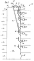
- Fig. 1
- einen vereinfachten Längsschnitt durch ein Wohngebäude mit sechs Stockwerken und einem Kellerstockwerk, bei dem nachträglich drei der vorhandenen Heizungsanlagen modernisiert und mit zusätzlichen Kaminrohren verbunden sind,
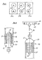
- Fig. 2
- Eine Draufsicht auf drei Adapterplatten bei einem vollständig modernisierten Wohngebäude,
- Fig. 3 und 4
- Bestandteile eines Montagesets zur Installation eines Kaminrohrs,
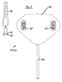
- Fig. 5
- eine Darstellung zur Erläuterung des Herstellens einer Verbindung zwischen dem Kaminende und der Anschlussstelle für eine zu modernisierende Heizungseinrichtung,
- Fig. 6
- eine Darstellung zur Erläuterung des Beginns des Einziehens eines Kaminrohrs durch einen Abgaskamin und
- Fig. 7
- das in dem Abgaskamin bereits an seiner Anschlussstelle montierte Kaminrohr bei einer Druckprüfung.
- Fig. 1
- a simplified longitudinal section through a residential building with six floors and a basement floor, in which subsequently upgraded three of the existing heating systems and are connected to additional chimney pipes,
- Fig. 2
- A top view of three adapter plates in a completely modernized residential building,
- 3 and 4
- Components of a mounting kit for installing a chimney pipe,
- Fig. 5
- a representation for explaining the establishment of a connection between the chimney end and the connection point for a heating device to be modernized,
- Fig. 6
- a representation for explaining the beginning of the drawing of a chimney pipe through an exhaust stack and
- Fig. 7
- in the exhaust stack already mounted at its junction chimney pipe at a pressure test.
Gleiche Bauteile bzw. Bauteile mit gleicher Funktion sind in den Figuren mit identischen Bezugsziffern versehen.The same components or components with the same function are provided in the figures with identical reference numerals.
In der
Der Abgaskamin 1 bildet in seinem Inneren einen Abgasschacht 20 aus, der zur Ableitung von Abgasen bzw. von Abwärme von Heizungsanlagen 21, 22 dient. Wesentlich hierbei ist, dass es sich den auf den Stockwerken 11, 12 und 14 installierten Heizungsanlage 21 jeweils um eine konventionelle Heizungsanlage, die beispielsweise mit Gas betrieben wird, handelt, welche relativ hohe Abgastemperaturen, von z.B. 160°C, erzeugt. Demgegenüber handelt es sich bei den Heizungsanlagen 22, welche in den Stockwerken 13, 15 und 16 installiert sind, um gegenüber der konventionellen Heizungsanlage 21 eine geringere Energiemenge verbrauchende Heizungsanlagen 22. Diese Heizungsanlagen 22 benötigt zur Ableitung ihrer Abgase ein spezielles Kaminrohr 25, dessen Installation in den vorhandenen Abgaskamin 1 Bestandteil dieser Erfindung ist. Es ist möglich, Heizungsanlagen 22 mit Kaminrohren 25 in beliebiger Reihenfolge im Wohngebäude 10 zu installieren.The exhaust chimney 1 forms in its interior an
Der Abgaskamin 1 weist für jede der Heizungsanlagen 21, 22 in der Wand 26 des Abgaskamins 1 jeweils einen Anschlussbereich 27 auf. Der Anschlussbereich 27 ist dabei insbesondere als Loch ausgebildet und ermöglicht die Ankopplung der jeweiligen Heizungsanlage 21, 22 an den Abgasschacht 20. Hierbei sind weitere Adapter- bzw. Anschlusselemente (nicht dargestellt) vorgesehen, die die jeweilige Heizungsanlage 21, 22 mit dem Anschlussbereich 27 verbinden.The exhaust gas chimney 1 has in each case one connecting
Wesentlich ist noch, dass im Bereich des. Abgasschachtes 18 jedem der Anschlussbereiche 27 ein Schutzelement 30 zugeordnet ist. Das sich senkrecht zur Zeichenebene der
Bei dem in der
Im dargestellten Ausführungsbeispiel gemäß der
Wesentlich ist noch, dass je nach Anzahl der (modernisierten) Heizungsanlagen 22 und auf welchem der Stockwerke 11 bis 16 sich die Heizungsanlagen 22 befinden, jedes der Kaminrohre 25 einer speziellen Adapterplatte 37a, 37b zugeordnet ist. Erfindungsgemäß ist es vorgesehen, dass zwischen einer und drei Adapterplatten 37a, 37b, 37c vorgesehen sind. Hierbei dient jede der Adapterplatten 37a, 37b, 37c zur Aufnahme von maximal zwei Kaminrohren 25.It is also essential that, depending on the number of (modernized)
In der
Ferner weist jede der Adapterplatten 37a, 37b, 37c zwei Aufnahmen 35 bzw. 36 auf. Wesentlich hierbei ist, dass die Aufnahme 35 einen geringeren Durchmesser aufweist als die Aufnahme 36. In der Adapterplatte 37a sind zwei Aufnahmen 35, in der Adapterplatte 37b ist jeweils eine Aufnahme 35, 36 und in der Adapterplatte 37c sind zwei Aufnahmen 36 vorgesehen. Beispielhaft weist die Aufnahme 35 einen Durchmesser von 63mm und die Aufnahme 36 einen Durchmesser von 80mm auf. Dementsprechend werden für die Aufnahmen 35, 36 auch Kaminrohre 25 mit unterschiedlichem Durchmesser verwendet, wobei der Durchmesser des Kaminrohrs 25 aus strömungstechnischen Gründen in Abhängigkeit der Länge des Kaminrohrs 25 mit größerer Länge, das heißt mit niedrigerem Stockwerk 11 bis 16 derart zunimmt, dass für die Stockwerke 11 bis 13 ein Kaminrohr 25 mit größerem Durchmesser verwendet wird als für die Stockwerke 14 bis 16. In der
Die Enden 33 der Kaminrohre 25 werden durch die Aufnahmen 35, 36 der Adapterplatten 37a, 37b, 37c geführt und mit der jeweiligen Adapterplatte 37a, 37b, 37c mittels nicht dargestellter, an sich bekannter Kaminrohrdurchführungselemente, insbesondre mittels eines aus elastischem Material bestehenden elastischen Aufhängungsringes 38 befestigt, sodass ein Durchrutschen der Enden 33 der Kaminrohre 25 in das Innere des Abgasschachtes 20 vermieden wird. bzw. Um Standardbauteile zur Befestigung der Kaminrohre 25 verwenden zu können, weisen diese insbesondere Normmaße bzw. Normdurchmesser auf.The ends 33 of the
Die Installation eines Kaminrohrs 25 wird nachfolgend anhand der Installation des Kaminrohrs 25 beschrieben, welches der Heizungsanlage 22 zugeordnet ist, die sich auf dem Stockwerk 16 befindet.The installation of a
Hierzu ist ein in den
Wesentlich ist, dass an dem dem Ballastgewicht 43 zugewandten Ende des Maßbandes 42 zusätzlich ein Magnetelement 47 angeordnet ist. Alternativ hierzu kann natürlich auch vorgesehen sein, dass das Ballastgewicht 43 selbst aus magnetischem Material besteht.It is essential that a
Das Herstellen der Verbindung zwischen dem Kaminende 34 und dem Anschlussbereich 27 erfolgt gemäß der
Gleichzeitig bzw. vorab wurde über den Anschlussbereich 27 des Stockwerks 16 die Blechplatte 44 in Richtung des Kaminendes 34 verbracht. Sobald sich das Magnetelement 47 und die Blechplatte 44 einander nähern, findet aufgrund der magnetischen Anziehungskraft eine mechanische Verbindung zwischen dem Magnetelement 47 bzw. dem Maßband 42 und der Blechplatte 44 statt. Sobald dies geschehen ist, kann die Blechplatte 44 mit dem Ende des Maßbandes 42 in den Bereich des Anschlussbereichs 27 heruntergezogen werden, sodass das Maßband 42 mitsamt dem Ballastgewicht 43 den Anschlussbereich 27 passiert. Nunmehr wird am Kaminende 34 der Wert für die Länge der Verbindung zwischen dem Anschlussbereich 27 und dem Kaminende 34 bzw. der dem Stockwerk 16 zugeordneten Adapterplatte 37a am Maßband 42 abgelesen, wodurch die benötigte Länge für das Kaminrohr 25 bestimmt werden kann. Gegebenenfalls kann diesem ermittelten Wert eine zusätzliche Länge zugeschlagen werden, um damit in jedem Fall eine genügende Länge des Kaminrohrs 25 zu gewährleisten bzw. die nachfolgende Montage der Enden 32, 33 des Kaminrohrs 25 zu erleichtern.At the same time or in advance, the
Nunmehr ist es erforderlich, die durch das Maßband 42 ausgebildete Verbindung zwischen dem Kaminende 34 und dem Anschlussbereich 27 des Stockwerks 16 durch ein zweites Hilfselement 50 in Form insbesondere einer Kunststoffschnur 51 zu ersetzen, um damit das Einziehen des Kaminrohrs 25 zu ermöglichen. Dieser, in den Figuren nicht dargestellte Vorgang wird dadurch bewirkt, dass entweder das Maßband 42 von der Seite des Ballastgewichtes 43 oder von dem gegenüberliegenden Ende her mit der Kunststoffschnur 51 verbunden wird und durch Einziehen der Kunststoffschnur 51 in den Abgasschacht 20 das Maßband 42 ersetzt wird.Now it is necessary, formed by the
Nachfolgend wird das dem Kaminende 34 zugeordnete Ende der Kunststoffschnur 51 mit einem ersten Adapterelement 52 (
Das Kaminrohr 25 ist vorzugsweise aus Kunststoff, hierbei insbesondere zumindest teilweise aus PVDF (Polyvinylidenfluorid), hergestellt. Insbesondere weist es zumindest einen Teilbereich auf, der flexibel ausgebildet ist, derart, dass dieser problemlos das Schutzelement 30 im Abgasschacht 20 passieren kann. Vorzugsweise ist das Kaminrohr 25 auf seiner gesamten Länge flexibel ausgebildet (Flexrohr).The
Das andere Ende 33 des Kaminrohrs 25 wird mit einem zweiten Adapterelement 57 (
Nachfolgend wird das Kaminrohr 25 entsprechend der
Wenn das eine, mit dem ersten Adapterelement 52 versehene Ende 32 des Kaminrohrs 25 den Anschlussbereich 27 passiert hat, kann das Kaminrohr 25 mit Befestigungselementen versehen werden, die eine Befestigung des Kaminrohrs 25 an den Anschlussbereich 27 ermöglichen. Dabei kann das andere Ende 33 des Kaminrohrs 25 sich innerhalb des Abgasschachtes 20 befinden, wobei es durch die Sicherungsplatte gesichert ist. Dadurch kann insbesondere das Ende 32 relativ weit in den Anschlussbereich 27 eingezogen werden, um die Montage der Befestigungselemente (nicht dargestellt) für das Ende 32 des Kaminrohrs 25 zu erleichtern ohne, dass hierzu das Kaminrohr 25 insgesamt besonders verlängert werden müsste. Danach wird das Ende 33 des Kaminrohrs 25 durch die Aufnahme 35 nach oben gezogen und das Seil 59 mit einer Federwaage 65 verbunden, wobei zuvor noch der Aufhängungsring 38 auf den Außenumfang des Kaminrohrs 25 übergeschoben wurde. Alternativ hierzu kann das zweite Adapterelement 57 auch direkt mit der Federwaage 65 verbunden werden. Dann wird auf das zweite Adapterelement 57 mittels der Federwaage 65 eine definierte Zugkraft ausgeübt. Dadurch wird das Kaminrohr 25 zwischen dem Anschlussbereich 27 und dem Kaminende 34 bzw. der Adapterplatte 37a gespannt bzw. dessen Länge minimiert (
Ergänzend wird erwähnt, dass es vorteilhafterweise vorgesehen sein kann, dass nach einer bestimmten Betriebsdauer der Heizungsanlagen 21, 22 erneut eine entsprechende Zugbelastung auf das Kaminrohr 25 ausgeübt wird, damit das Kaminrohr 25 nachgespannt werden kann.In addition, it is mentioned that it may be advantageously provided that after a certain period of operation of the
Nachdem das der Adapterplatte 37a zugewandte Ende 33 des Kaminrohrs 25 mit der Adapterplatte 37a verbunden ist, kann eine Druckprüfung des Kaminrohrs 25 stattfinden, um evtl. während der Installation erfolgte Beschädigungen bzw. Undichtheiten des Kaminrohrs 25 erkennen zu können. Hierzu wird das erste Adapterelement 52 über einen Druckanschluss 67 mit einer Überdruckeinrichtung 68 gekoppelt und der Innenraum des Kaminrohrs 25 einem Überdruck ausgesetzt. Sollte daraufhin der Druck in dem Kaminrohr 25 innerhalb einer bestimmten Zeit stabil bleiben, wird daraus auf eine Dichtheit des Kaminrohrs 25 geschlossen. In den Fall, dass der Druck im Abgasrohr 25 um mehr als einen bestimmten Wert abnimmt, muss nach der Ursache der Undichtheit gesucht werden. Nach erfolgter Drucküberprüfung können die überstehenden Enden 32, 33 des Kaminrohrs 25 abgeschnitten werden. Dadurch ist die Installation des Kaminrohrs 25 abgeschlossen.After the
Das soweit beschriebene Verfahren zur Installation eines Kaminrohrs 25 für eine Heizungsanlage 22 in einem Abgaskamin 1 kann in vielfältiger Art und Weise modifiziert bzw. abgewandelt werden, ohne vom Erfindungsgedanken abzuweichen.The method described so far for the installation of a
Claims (14)
- Method for installing a chimney pipe (25) for a heating facility (22) in a waste gas chimney (1), wherein the waste gas chimney (1) has a waste gas shaft (20) having an upper chimney end (34) which is operatively connected to the surroundings of a housing (10) and a connection region (27) arranged in a wall (26) of the waste gas chamber (1), wherein the chimney pipe (25) is arranged at least between the chimney end (34) and the connection region (27), and wherein the installation of the chimney pipe (25) comprises the following steps:- producing a connection between the chimney end (34) and the connection region (27) by means of at least one auxiliary means (41, 51);- connecting the at least one auxiliary means (41, 51) to the chimney pipe (25) at the chimney end (34) side or the connection region (27) side;- inserting the chimney pipe (25) into the waste gas chimney (1) by means of the at least one auxiliary means (41, 51); and- connecting the ends (32, 33) of the chimney pipe (25) in the region of the chimney end (34) to the waste gas chimney (1) in one case and to the connection region (27) in the other case,characterised in that the at least one auxiliary means (41) comprises a first part (44), which is inserted from the connection region (27) side into the waste gas chimney (1), in that a second part (42) of the first auxiliary means (41) is inserted from the chimney end (34) into the waste gas chimney (1), and in that the two ends of the parts (42, 44) contact each other in the waste gas chimney (1) in such a way that a mechanically loadable connection is produced between the two parts (42, 44).
- Method according to claim 1, characterised in that the first part (44) is connected to a pliant element (46) and has, at least on the side at which the connection to the second part (42) is produced, a first magnetic region, and in that the second part (42) has a second magnetic region (47) on the side facing the first part (44), in such a way that the two magnetic regions (44, 47) attract each other.
- Method according to either claim 1 or claim 2, characterised in that the first part (44) is constructed in the form of a sheet metal plate, in that the second part has at least one flexible element in the form of a cord or of a belt (42), in that the end of the cord or of the belt (42) inserted into the waste gas chimney (1) is provided with a ballast weight (43) that tautens the cord or the belt (42), and in that the ballast weight (43) or the end of the sheet metal plate (44) facing the ballast weight (43) has a magnet element (47).
- Method according to claim 3, characterised in that a measuring tape (42) is used as the belt, and in that the required length of the chimney pipe (25) is established by means of the measuring tape (42) after the connection between the chimney end (34) and the connection region (27) has been produced.
- Method according to any of claims 1 to 4, characterised in that the method additionally comprises applying at least one adapter plate (37a, 37b, 37c) at the chimney end (34) side and fixing the chimney pipe (25) to one of the adapter plates (37a, 37b, 37c).
- Method according to any of claims 1 to 5, characterised in that the at least one first auxiliary means (41) is replaced by means of the at least one first auxiliary means (41) with a second auxiliary means, in particular in the form of a plastics cord (51), after the connection between the chimney end (34) and the connection region (27) has been produced, the strength of the plastics cord (51) being such that it bears at least the weight of the chimney pipe (25) without incurring damage.
- Method according to any of claims 1 to 6, characterised in that the insertion of the chimney pipe (25) into the waste gas chimney (1) is carried out from the chimney end (34) side, in that the end (32) of the chimney pipe (25) facing the connection region (27) is connected to a first adapter element (52), and in that the end (33) of the chimney pipe (25) which is assigned to the chimney end (34) is connected at least indirectly to the chimney end (34) after the end (32) of the chimney pipe (25) has been connected to the connection region (27).
- Method according to claim 7, characterised in that the chimney pipe (25) is constructed so as to be flexible at least in part.
- Method according to either claim 7 or claim 8, characterised in that the chimney pipe (25) consists, at least in part, of plastics material, in particular of PVDF (polyvinylidenfluoride).
- Method according to any of claims 7 to 9, characterised in that the chimney pipe (25) is subjected to a tensile load prior to connection to the chimney end (34), and in that the chimney pipe (25) is connected to the chimney end (34) under tensile loading.
- Method according to any of claims 1 to 10, characterised in that the method additionally comprises the method step of checking the impermeability of the chimney pipe (25) after the assembly thereof between the chimney end (34) and the connection location (27).
- Method according to claim 11, characterised in that the checking is carried out by means of an overpressure source (68), the two ends (32, 33) of the chimney pipe (25) being closed and the chimney pipe (25) being subjected to overpressure.
- Method according to any of claims 5 to 12, characterised in that, when a plurality of chimney pipes (25) is installed, the ends (33) of the chimney pipes (25) facing the chimney end (34) are each assigned special receivers (35, 36) in the adapter element (37a, 37b, 37c).
- Assembly kit (40) for use in a method for installing a chimney pipe (25) for a heating facility (22) in a waste gas chimney (1) according to any of claims 1 to 13, the assembly kit (40) comprising at least one first auxiliary means (41) for producing a connection between the chimney end (34) and the connection region (27) and for inserting the chimney pipe into the waste gas chimney, means for fixing the one end (32) of the chimney pipe (25) to the connection region (27) and means for at least indirectly connecting the other end (33) of the chimney pipe (25) to the chimney end (34), characterised in that the at least one auxiliary means (41) comprises a first part (44), which is inserted from the connection region (27) side into the waste gas chimney (1), in that a second part (42) of the first auxiliary means (41) is inserted from the chimney end (34) into the waste gas chimney (1), and in that the two ends of the parts (42, 44) contact each other in the waste gas chimney (1) in such a way that a mechanically loadable connection is produced between the two parts (42, 44).
Priority Applications (1)
| Application Number | Priority Date | Filing Date | Title |
|---|---|---|---|
| EP20100002366 EP2365249B1 (en) | 2010-03-08 | 2010-03-08 | Method for installing a chimney pipe for a heating assembly in a waste gas chimney and assembly set |
Applications Claiming Priority (1)
| Application Number | Priority Date | Filing Date | Title |
|---|---|---|---|
| EP20100002366 EP2365249B1 (en) | 2010-03-08 | 2010-03-08 | Method for installing a chimney pipe for a heating assembly in a waste gas chimney and assembly set |
Publications (2)
| Publication Number | Publication Date |
|---|---|
| EP2365249A1 EP2365249A1 (en) | 2011-09-14 |
| EP2365249B1 true EP2365249B1 (en) | 2013-05-29 |
Family
ID=42312840
Family Applications (1)
| Application Number | Title | Priority Date | Filing Date |
|---|---|---|---|
| EP20100002366 Active EP2365249B1 (en) | 2010-03-08 | 2010-03-08 | Method for installing a chimney pipe for a heating assembly in a waste gas chimney and assembly set |
Country Status (1)
| Country | Link |
|---|---|
| EP (1) | EP2365249B1 (en) |
Cited By (1)
| Publication number | Priority date | Publication date | Assignee | Title |
|---|---|---|---|---|
| EP3839343A1 (en) | 2019-12-19 | 2021-06-23 | Societe Exploitation Tolerie Emaillerie Nantaise | Assembly kit for dual-flow collective pipe |
Families Citing this family (2)
| Publication number | Priority date | Publication date | Assignee | Title |
|---|---|---|---|---|
| DE102012112236B4 (en) | 2012-12-13 | 2024-10-24 | Technaflon Kaminsysteme AG | Method for installing a chimney pipe for a heating system in an exhaust chimney and aid for carrying out the method |
| GB2524740A (en) * | 2014-03-31 | 2015-10-07 | Michael Davy Wadge | Device and method relating to the installation of a liner in a chimney or flue |
Family Cites Families (4)
| Publication number | Priority date | Publication date | Assignee | Title |
|---|---|---|---|---|
| IT1042501B (en) * | 1977-08-11 | 1980-01-30 | Marinni Battista S P A Impresa | CIMINI AND SOUTH MATORO BUILDING THEM |
| US6029655A (en) * | 1998-04-27 | 2000-02-29 | Hussong Manufacturing Co., Inc. | Modular gas fireplace insert |
| DE29815970U1 (en) * | 1998-09-08 | 1999-03-18 | Technaflon AG, Tägerwilen | Chimney pipe |
| FR2818965B1 (en) * | 2001-01-04 | 2003-05-30 | Michel Gautier | APPARATUS FOR INTERNAL DUCTING OF CONDUITS |
-
2010
- 2010-03-08 EP EP20100002366 patent/EP2365249B1/en active Active
Cited By (1)
| Publication number | Priority date | Publication date | Assignee | Title |
|---|---|---|---|---|
| EP3839343A1 (en) | 2019-12-19 | 2021-06-23 | Societe Exploitation Tolerie Emaillerie Nantaise | Assembly kit for dual-flow collective pipe |
Also Published As
| Publication number | Publication date |
|---|---|
| EP2365249A1 (en) | 2011-09-14 |
Similar Documents
| Publication | Publication Date | Title |
|---|---|---|
| DE202008012120U1 (en) | Holding device for a sprinkler nozzle | |
| EP2365249A1 (en) | Method for installing a chimney pipe for a heating assembly in a waste gas chimney and assembly set | |
| EP0437260A1 (en) | Ceramic sleeve for coating a chimney. | |
| EP2365248B1 (en) | Flue gas chimney for heating installations and chimney pipe for same | |
| DE102012112852B4 (en) | Pipe bends for exhaust gas routing in heating systems | |
| EP0443223B1 (en) | Pipe section for a pipe conduit consisting of several parts | |
| BE1021800B1 (en) | METHOD FOR INSTALLING A FIREPLACE FOR A HEATING SYSTEM IN AN EXHAUST GAS AND AID FOR IMPLEMENTING THE PROCESS | |
| DE202015002187U1 (en) | Support and clamping parts for mounting components, in particular in dry construction and for overhead mounting | |
| AT522944B1 (en) | Seal assembly and pipe assembly | |
| EP2607786B1 (en) | Assembly with a pipe bend for waste gas conduction in heating installations | |
| EP0289783B1 (en) | Application system for installing a flue gas pipe system in a chimney | |
| DE102011054617A1 (en) | Device for temporarily fixing a pipe unit | |
| DE102017207053B4 (en) | Exhaust pipe and method for cutting an exhaust pipe | |
| EP0344151B1 (en) | Means for repairing pipes by remote-controlled insertion of a lining | |
| AT505255B1 (en) | CHIMNEY | |
| DE4231760C2 (en) | Plug connection for insert pipes made of stainless steel, in particular for smoke, exhaust gas, ventilation and exhaust systems and use thereof | |
| DE102007026729A1 (en) | Pipework device for carrying pipework through a roof with roofing foil has a first part with a connection piece and a ring made from foam material to surround a first pipe connection piece | |
| EP0668463A1 (en) | Spacer | |
| AT523245B1 (en) | Heating device, in particular gas condensing device | |
| DE10254397B4 (en) | Universal hose coupling | |
| DE19939398A1 (en) | Socketed pipe system for exhaust shafts has centring elements on centring device adjoining with sliding action against outside wall of spigot end section to ensure central alignment | |
| DE10115676B4 (en) | Method and device for retrofitting a gas flow monitor in a house connection line | |
| DE20014625U1 (en) | Device for testing pipelines | |
| DE1683736C (en) | Chimney or duct | |
| DE202020106329U1 (en) | Temporary downspout |
Legal Events
| Date | Code | Title | Description |
|---|---|---|---|
| PUAI | Public reference made under article 153(3) epc to a published international application that has entered the european phase |
Free format text: ORIGINAL CODE: 0009012 |
|
| AK | Designated contracting states |
Kind code of ref document: A1 Designated state(s): AT BE BG CH CY CZ DE DK EE ES FI FR GB GR HR HU IE IS IT LI LT LU LV MC MK MT NL NO PL PT RO SE SI SK SM TR |
|
| AX | Request for extension of the european patent |
Extension state: AL BA ME RS |
|
| 17P | Request for examination filed |
Effective date: 20120314 |
|
| GRAP | Despatch of communication of intention to grant a patent |
Free format text: ORIGINAL CODE: EPIDOSNIGR1 |
|
| GRAS | Grant fee paid |
Free format text: ORIGINAL CODE: EPIDOSNIGR3 |
|
| GRAA | (expected) grant |
Free format text: ORIGINAL CODE: 0009210 |
|
| AK | Designated contracting states |
Kind code of ref document: B1 Designated state(s): AT BE BG CH CY CZ DE DK EE ES FI FR GB GR HR HU IE IS IT LI LT LU LV MC MK MT NL NO PL PT RO SE SI SK SM TR |
|
| REG | Reference to a national code |
Ref country code: GB Ref legal event code: FG4D Free format text: NOT ENGLISH |
|
| REG | Reference to a national code |
Ref country code: CH Ref legal event code: EP |
|
| REG | Reference to a national code |
Ref country code: AT Ref legal event code: REF Ref document number: 614653 Country of ref document: AT Kind code of ref document: T Effective date: 20130615 |
|
| REG | Reference to a national code |
Ref country code: IE Ref legal event code: FG4D Free format text: LANGUAGE OF EP DOCUMENT: GERMAN |
|
| REG | Reference to a national code |
Ref country code: DE Ref legal event code: R096 Ref document number: 502010003395 Country of ref document: DE Effective date: 20130725 |
|
| REG | Reference to a national code |
Ref country code: LT Ref legal event code: MG4D |
|
| PG25 | Lapsed in a contracting state [announced via postgrant information from national office to epo] |
Ref country code: SI Free format text: LAPSE BECAUSE OF FAILURE TO SUBMIT A TRANSLATION OF THE DESCRIPTION OR TO PAY THE FEE WITHIN THE PRESCRIBED TIME-LIMIT Effective date: 20130529 Ref country code: SE Free format text: LAPSE BECAUSE OF FAILURE TO SUBMIT A TRANSLATION OF THE DESCRIPTION OR TO PAY THE FEE WITHIN THE PRESCRIBED TIME-LIMIT Effective date: 20130529 Ref country code: IS Free format text: LAPSE BECAUSE OF FAILURE TO SUBMIT A TRANSLATION OF THE DESCRIPTION OR TO PAY THE FEE WITHIN THE PRESCRIBED TIME-LIMIT Effective date: 20130929 Ref country code: PT Free format text: LAPSE BECAUSE OF FAILURE TO SUBMIT A TRANSLATION OF THE DESCRIPTION OR TO PAY THE FEE WITHIN THE PRESCRIBED TIME-LIMIT Effective date: 20130930 Ref country code: NO Free format text: LAPSE BECAUSE OF FAILURE TO SUBMIT A TRANSLATION OF THE DESCRIPTION OR TO PAY THE FEE WITHIN THE PRESCRIBED TIME-LIMIT Effective date: 20130829 Ref country code: FI Free format text: LAPSE BECAUSE OF FAILURE TO SUBMIT A TRANSLATION OF THE DESCRIPTION OR TO PAY THE FEE WITHIN THE PRESCRIBED TIME-LIMIT Effective date: 20130529 Ref country code: GR Free format text: LAPSE BECAUSE OF FAILURE TO SUBMIT A TRANSLATION OF THE DESCRIPTION OR TO PAY THE FEE WITHIN THE PRESCRIBED TIME-LIMIT Effective date: 20130830 Ref country code: LT Free format text: LAPSE BECAUSE OF FAILURE TO SUBMIT A TRANSLATION OF THE DESCRIPTION OR TO PAY THE FEE WITHIN THE PRESCRIBED TIME-LIMIT Effective date: 20130529 Ref country code: ES Free format text: LAPSE BECAUSE OF FAILURE TO SUBMIT A TRANSLATION OF THE DESCRIPTION OR TO PAY THE FEE WITHIN THE PRESCRIBED TIME-LIMIT Effective date: 20130909 |
|
| REG | Reference to a national code |
Ref country code: NL Ref legal event code: VDEP Effective date: 20130529 |
|
| PG25 | Lapsed in a contracting state [announced via postgrant information from national office to epo] |
Ref country code: PL Free format text: LAPSE BECAUSE OF FAILURE TO SUBMIT A TRANSLATION OF THE DESCRIPTION OR TO PAY THE FEE WITHIN THE PRESCRIBED TIME-LIMIT Effective date: 20130529 Ref country code: BG Free format text: LAPSE BECAUSE OF FAILURE TO SUBMIT A TRANSLATION OF THE DESCRIPTION OR TO PAY THE FEE WITHIN THE PRESCRIBED TIME-LIMIT Effective date: 20130829 Ref country code: HR Free format text: LAPSE BECAUSE OF FAILURE TO SUBMIT A TRANSLATION OF THE DESCRIPTION OR TO PAY THE FEE WITHIN THE PRESCRIBED TIME-LIMIT Effective date: 20130529 |
|
| PG25 | Lapsed in a contracting state [announced via postgrant information from national office to epo] |
Ref country code: LV Free format text: LAPSE BECAUSE OF FAILURE TO SUBMIT A TRANSLATION OF THE DESCRIPTION OR TO PAY THE FEE WITHIN THE PRESCRIBED TIME-LIMIT Effective date: 20130529 |
|
| PG25 | Lapsed in a contracting state [announced via postgrant information from national office to epo] |
Ref country code: DK Free format text: LAPSE BECAUSE OF FAILURE TO SUBMIT A TRANSLATION OF THE DESCRIPTION OR TO PAY THE FEE WITHIN THE PRESCRIBED TIME-LIMIT Effective date: 20130529 Ref country code: EE Free format text: LAPSE BECAUSE OF FAILURE TO SUBMIT A TRANSLATION OF THE DESCRIPTION OR TO PAY THE FEE WITHIN THE PRESCRIBED TIME-LIMIT Effective date: 20130529 Ref country code: CZ Free format text: LAPSE BECAUSE OF FAILURE TO SUBMIT A TRANSLATION OF THE DESCRIPTION OR TO PAY THE FEE WITHIN THE PRESCRIBED TIME-LIMIT Effective date: 20130529 Ref country code: SK Free format text: LAPSE BECAUSE OF FAILURE TO SUBMIT A TRANSLATION OF THE DESCRIPTION OR TO PAY THE FEE WITHIN THE PRESCRIBED TIME-LIMIT Effective date: 20130529 |
|
| PG25 | Lapsed in a contracting state [announced via postgrant information from national office to epo] |
Ref country code: RO Free format text: LAPSE BECAUSE OF FAILURE TO SUBMIT A TRANSLATION OF THE DESCRIPTION OR TO PAY THE FEE WITHIN THE PRESCRIBED TIME-LIMIT Effective date: 20130529 Ref country code: IT Free format text: LAPSE BECAUSE OF FAILURE TO SUBMIT A TRANSLATION OF THE DESCRIPTION OR TO PAY THE FEE WITHIN THE PRESCRIBED TIME-LIMIT Effective date: 20130529 Ref country code: NL Free format text: LAPSE BECAUSE OF FAILURE TO SUBMIT A TRANSLATION OF THE DESCRIPTION OR TO PAY THE FEE WITHIN THE PRESCRIBED TIME-LIMIT Effective date: 20130529 |
|
| PLBE | No opposition filed within time limit |
Free format text: ORIGINAL CODE: 0009261 |
|
| STAA | Information on the status of an ep patent application or granted ep patent |
Free format text: STATUS: NO OPPOSITION FILED WITHIN TIME LIMIT |
|
| 26N | No opposition filed |
Effective date: 20140303 |
|
| REG | Reference to a national code |
Ref country code: DE Ref legal event code: R097 Ref document number: 502010003395 Country of ref document: DE Effective date: 20140303 |
|
| PGFP | Annual fee paid to national office [announced via postgrant information from national office to epo] |
Ref country code: CH Payment date: 20140410 Year of fee payment: 5 |
|
| REG | Reference to a national code |
Ref country code: DE Ref legal event code: R119 Ref document number: 502010003395 Country of ref document: DE |
|
| PG25 | Lapsed in a contracting state [announced via postgrant information from national office to epo] |
Ref country code: LU Free format text: LAPSE BECAUSE OF FAILURE TO SUBMIT A TRANSLATION OF THE DESCRIPTION OR TO PAY THE FEE WITHIN THE PRESCRIBED TIME-LIMIT Effective date: 20140308 |
|
| GBPC | Gb: european patent ceased through non-payment of renewal fee |
Effective date: 20140308 |
|
| REG | Reference to a national code |
Ref country code: IE Ref legal event code: MM4A |
|
| REG | Reference to a national code |
Ref country code: DE Ref legal event code: R119 Ref document number: 502010003395 Country of ref document: DE Effective date: 20141001 |
|
| PG25 | Lapsed in a contracting state [announced via postgrant information from national office to epo] |
Ref country code: IE Free format text: LAPSE BECAUSE OF NON-PAYMENT OF DUE FEES Effective date: 20140308 Ref country code: DE Free format text: LAPSE BECAUSE OF NON-PAYMENT OF DUE FEES Effective date: 20141001 Ref country code: GB Free format text: LAPSE BECAUSE OF NON-PAYMENT OF DUE FEES Effective date: 20140308 |
|
| REG | Reference to a national code |
Ref country code: CH Ref legal event code: PL |
|
| PG25 | Lapsed in a contracting state [announced via postgrant information from national office to epo] |
Ref country code: CH Free format text: LAPSE BECAUSE OF NON-PAYMENT OF DUE FEES Effective date: 20150331 Ref country code: LI Free format text: LAPSE BECAUSE OF NON-PAYMENT OF DUE FEES Effective date: 20150331 |
|
| PG25 | Lapsed in a contracting state [announced via postgrant information from national office to epo] |
Ref country code: MT Free format text: LAPSE BECAUSE OF FAILURE TO SUBMIT A TRANSLATION OF THE DESCRIPTION OR TO PAY THE FEE WITHIN THE PRESCRIBED TIME-LIMIT Effective date: 20130529 |
|
| REG | Reference to a national code |
Ref country code: FR Ref legal event code: PLFP Year of fee payment: 7 |
|
| PG25 | Lapsed in a contracting state [announced via postgrant information from national office to epo] |
Ref country code: SM Free format text: LAPSE BECAUSE OF FAILURE TO SUBMIT A TRANSLATION OF THE DESCRIPTION OR TO PAY THE FEE WITHIN THE PRESCRIBED TIME-LIMIT Effective date: 20130529 |
|
| REG | Reference to a national code |
Ref country code: AT Ref legal event code: MM01 Ref document number: 614653 Country of ref document: AT Kind code of ref document: T Effective date: 20150308 |
|
| PG25 | Lapsed in a contracting state [announced via postgrant information from national office to epo] |
Ref country code: MC Free format text: LAPSE BECAUSE OF FAILURE TO SUBMIT A TRANSLATION OF THE DESCRIPTION OR TO PAY THE FEE WITHIN THE PRESCRIBED TIME-LIMIT Effective date: 20130529 |
|
| PG25 | Lapsed in a contracting state [announced via postgrant information from national office to epo] |
Ref country code: CY Free format text: LAPSE BECAUSE OF FAILURE TO SUBMIT A TRANSLATION OF THE DESCRIPTION OR TO PAY THE FEE WITHIN THE PRESCRIBED TIME-LIMIT Effective date: 20130529 |
|
| PG25 | Lapsed in a contracting state [announced via postgrant information from national office to epo] |
Ref country code: TR Free format text: LAPSE BECAUSE OF FAILURE TO SUBMIT A TRANSLATION OF THE DESCRIPTION OR TO PAY THE FEE WITHIN THE PRESCRIBED TIME-LIMIT Effective date: 20130529 Ref country code: HU Free format text: LAPSE BECAUSE OF FAILURE TO SUBMIT A TRANSLATION OF THE DESCRIPTION OR TO PAY THE FEE WITHIN THE PRESCRIBED TIME-LIMIT; INVALID AB INITIO Effective date: 20100308 |
|
| PG25 | Lapsed in a contracting state [announced via postgrant information from national office to epo] |
Ref country code: AT Free format text: LAPSE BECAUSE OF NON-PAYMENT OF DUE FEES Effective date: 20150308 |
|
| REG | Reference to a national code |
Ref country code: FR Ref legal event code: PLFP Year of fee payment: 8 |
|
| PG25 | Lapsed in a contracting state [announced via postgrant information from national office to epo] |
Ref country code: BE Free format text: LAPSE BECAUSE OF NON-PAYMENT OF DUE FEES Effective date: 20140331 |
|
| PG25 | Lapsed in a contracting state [announced via postgrant information from national office to epo] |
Ref country code: MK Free format text: LAPSE BECAUSE OF FAILURE TO SUBMIT A TRANSLATION OF THE DESCRIPTION OR TO PAY THE FEE WITHIN THE PRESCRIBED TIME-LIMIT Effective date: 20130529 |
|
| REG | Reference to a national code |
Ref country code: FR Ref legal event code: PLFP Year of fee payment: 9 |
|
| REG | Reference to a national code |
Ref country code: FR Ref legal event code: TP Owner name: AGNES MARGARETE WUNSCH, CH Effective date: 20180806 |
|
| PGFP | Annual fee paid to national office [announced via postgrant information from national office to epo] |
Ref country code: FR Payment date: 20250324 Year of fee payment: 16 |