EP2365255A2 - Klimaanlagenvorrichtung - Google Patents
Klimaanlagenvorrichtung Download PDFInfo
- Publication number
- EP2365255A2 EP2365255A2 EP11157489A EP11157489A EP2365255A2 EP 2365255 A2 EP2365255 A2 EP 2365255A2 EP 11157489 A EP11157489 A EP 11157489A EP 11157489 A EP11157489 A EP 11157489A EP 2365255 A2 EP2365255 A2 EP 2365255A2
- Authority
- EP
- European Patent Office
- Prior art keywords
- outdoor unit
- outdoor
- unit
- indoor
- housing
- Prior art date
- Legal status (The legal status is an assumption and is not a legal conclusion. Google has not performed a legal analysis and makes no representation as to the accuracy of the status listed.)
- Withdrawn
Links
Images


Classifications
-
- F—MECHANICAL ENGINEERING; LIGHTING; HEATING; WEAPONS; BLASTING
- F24—HEATING; RANGES; VENTILATING
- F24F—AIR-CONDITIONING; AIR-HUMIDIFICATION; VENTILATION; USE OF AIR CURRENTS FOR SCREENING
- F24F3/00—Air-conditioning systems in which conditioned primary air is supplied from one or more central stations to distributing units in the rooms or spaces where it may receive secondary treatment; Apparatus specially designed for such systems
- F24F3/06—Air-conditioning systems in which conditioned primary air is supplied from one or more central stations to distributing units in the rooms or spaces where it may receive secondary treatment; Apparatus specially designed for such systems characterised by the arrangements for the supply of heat-exchange fluid for the subsequent treatment of primary air in the room units
- F24F3/065—Air-conditioning systems in which conditioned primary air is supplied from one or more central stations to distributing units in the rooms or spaces where it may receive secondary treatment; Apparatus specially designed for such systems characterised by the arrangements for the supply of heat-exchange fluid for the subsequent treatment of primary air in the room units with a plurality of evaporators or condensers
-
- F—MECHANICAL ENGINEERING; LIGHTING; HEATING; WEAPONS; BLASTING
- F24—HEATING; RANGES; VENTILATING
- F24F—AIR-CONDITIONING; AIR-HUMIDIFICATION; VENTILATION; USE OF AIR CURRENTS FOR SCREENING
- F24F1/00—Room units for air-conditioning, e.g. separate or self-contained units or units receiving primary air from a central station
- F24F1/02—Self-contained room units for air-conditioning, i.e. with all apparatus for treatment installed in a common casing
-
- F—MECHANICAL ENGINEERING; LIGHTING; HEATING; WEAPONS; BLASTING
- F24—HEATING; RANGES; VENTILATING
- F24F—AIR-CONDITIONING; AIR-HUMIDIFICATION; VENTILATION; USE OF AIR CURRENTS FOR SCREENING
- F24F1/00—Room units for air-conditioning, e.g. separate or self-contained units or units receiving primary air from a central station
- F24F1/06—Separate outdoor units, e.g. outdoor unit to be linked to a separate room comprising a compressor and a heat exchanger
- F24F1/26—Refrigerant piping
- F24F1/32—Refrigerant piping for connecting the separate outdoor units to indoor units
-
- F—MECHANICAL ENGINEERING; LIGHTING; HEATING; WEAPONS; BLASTING
- F24—HEATING; RANGES; VENTILATING
- F24F—AIR-CONDITIONING; AIR-HUMIDIFICATION; VENTILATION; USE OF AIR CURRENTS FOR SCREENING
- F24F1/00—Room units for air-conditioning, e.g. separate or self-contained units or units receiving primary air from a central station
- F24F1/06—Separate outdoor units, e.g. outdoor unit to be linked to a separate room comprising a compressor and a heat exchanger
- F24F1/56—Casing or covers of separate outdoor units, e.g. fan guards
-
- F—MECHANICAL ENGINEERING; LIGHTING; HEATING; WEAPONS; BLASTING
- F24—HEATING; RANGES; VENTILATING
- F24F—AIR-CONDITIONING; AIR-HUMIDIFICATION; VENTILATION; USE OF AIR CURRENTS FOR SCREENING
- F24F1/00—Room units for air-conditioning, e.g. separate or self-contained units or units receiving primary air from a central station
- F24F1/06—Separate outdoor units, e.g. outdoor unit to be linked to a separate room comprising a compressor and a heat exchanger
- F24F1/60—Arrangement or mounting of the outdoor unit
-
- F—MECHANICAL ENGINEERING; LIGHTING; HEATING; WEAPONS; BLASTING
- F25—REFRIGERATION OR COOLING; COMBINED HEATING AND REFRIGERATION SYSTEMS; HEAT PUMP SYSTEMS; MANUFACTURE OR STORAGE OF ICE; LIQUEFACTION SOLIDIFICATION OF GASES
- F25B—REFRIGERATION MACHINES, PLANTS OR SYSTEMS; COMBINED HEATING AND REFRIGERATION SYSTEMS; HEAT PUMP SYSTEMS
- F25B13/00—Compression machines, plants or systems, with reversible cycle
-
- F—MECHANICAL ENGINEERING; LIGHTING; HEATING; WEAPONS; BLASTING
- F25—REFRIGERATION OR COOLING; COMBINED HEATING AND REFRIGERATION SYSTEMS; HEAT PUMP SYSTEMS; MANUFACTURE OR STORAGE OF ICE; LIQUEFACTION SOLIDIFICATION OF GASES
- F25B—REFRIGERATION MACHINES, PLANTS OR SYSTEMS; COMBINED HEATING AND REFRIGERATION SYSTEMS; HEAT PUMP SYSTEMS
- F25B41/00—Fluid-circulation arrangements
- F25B41/40—Fluid line arrangements
- F25B41/42—Arrangements for diverging or converging flows, e.g. branch lines or junctions
-
- F—MECHANICAL ENGINEERING; LIGHTING; HEATING; WEAPONS; BLASTING
- F25—REFRIGERATION OR COOLING; COMBINED HEATING AND REFRIGERATION SYSTEMS; HEAT PUMP SYSTEMS; MANUFACTURE OR STORAGE OF ICE; LIQUEFACTION SOLIDIFICATION OF GASES
- F25B—REFRIGERATION MACHINES, PLANTS OR SYSTEMS; COMBINED HEATING AND REFRIGERATION SYSTEMS; HEAT PUMP SYSTEMS
- F25B2313/00—Compression machines, plants or systems with reversible cycle not otherwise provided for
- F25B2313/006—Compression machines, plants or systems with reversible cycle not otherwise provided for two pipes connecting the outdoor side to the indoor side with multiple indoor units
-
- F—MECHANICAL ENGINEERING; LIGHTING; HEATING; WEAPONS; BLASTING
- F25—REFRIGERATION OR COOLING; COMBINED HEATING AND REFRIGERATION SYSTEMS; HEAT PUMP SYSTEMS; MANUFACTURE OR STORAGE OF ICE; LIQUEFACTION SOLIDIFICATION OF GASES
- F25B—REFRIGERATION MACHINES, PLANTS OR SYSTEMS; COMBINED HEATING AND REFRIGERATION SYSTEMS; HEAT PUMP SYSTEMS
- F25B2313/00—Compression machines, plants or systems with reversible cycle not otherwise provided for
- F25B2313/023—Compression machines, plants or systems with reversible cycle not otherwise provided for using multiple indoor units
-
- F—MECHANICAL ENGINEERING; LIGHTING; HEATING; WEAPONS; BLASTING
- F25—REFRIGERATION OR COOLING; COMBINED HEATING AND REFRIGERATION SYSTEMS; HEAT PUMP SYSTEMS; MANUFACTURE OR STORAGE OF ICE; LIQUEFACTION SOLIDIFICATION OF GASES
- F25B—REFRIGERATION MACHINES, PLANTS OR SYSTEMS; COMBINED HEATING AND REFRIGERATION SYSTEMS; HEAT PUMP SYSTEMS
- F25B2313/00—Compression machines, plants or systems with reversible cycle not otherwise provided for
- F25B2313/027—Compression machines, plants or systems with reversible cycle not otherwise provided for characterised by the reversing means
- F25B2313/02741—Compression machines, plants or systems with reversible cycle not otherwise provided for characterised by the reversing means using one four-way valve
Definitions
- This relates to an air conditioning device.
- An air conditioning device is a cooling/heating system that cools a space by repeatedly suctioning indoor air, performing heat exchange between a low-temperature refrigerant and the suctioned indoor air, and discharging the heat-exchanged air into the space, and that heats a space by repeatedly performing the above operations in reverse.
- Such an air conditioning device may include a compressor, an outdoor heat exchanger, an expansion valve, and an indoor heat exchanger.
- Such air conditioning devices may also include, for example, an air purification function and a dehumidification function in addition to cooling and heating of the air conditioning space.
- An air conditioning device according to the present invention is defined in the independent claims 1 and 11, An outdoor unit of an air conditioning device preferably according to any of claims 1 to 13 is defined in the independent claim 14. A method of operating an apparatus as described herein is defined in claim 16. The dependent claims relate to further aspects of the invention.
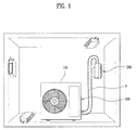
- FIG. 1 illustrates various exemplary installations of a distribution unit connected to an outdoor unit of an air conditioning device as embodied and broadly described herein;
- FIG. 2 illustrates an exemplary installation of distribution unit mounted in an installation space defined in an outdoor unit of an air conditioning device as embodied and broadly described herein;
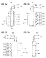
- FIGs. 3A-3D are various views of a distribution unit of an air conditioning device as embodied and broadly described herein;
- FIG. 4 is a perspective view of the distribution unit of the air conditioning device shown in FIGs. 1-3 ;
- FIGs. 5 and 6 are block diagrams illustrating refrigerant flow in a cooling mode of the air conditioning device as embodied and broadly described herein;
- FIGs. 7 and 8 are block diagrams illustrating refrigerant flow in a heating mode of the air conditioning device as embodied and broadly described herein,
- Air conditioning devices may be classified as separate air conditioning devices, in which an outdoor unit and an indoor unit are separately installed, and integrated air conditioning devices, in which an outdoor unit and an indoor unit are integrally installed.
- multi type air conditioning devices a plurality of indoor units may be connected to a single outdoor unit so as to commonly use the single outdoor unit.
- Such multi type air conditioning devices may provide air conditioning similar to that obtained by installing a plurality of separate air conditioning devices each including a single outdoor unit and a corresponding single indoor unit
- Such multi type air conditioning devices allow indoor units to be added as needed, depending on the capacity of the single outdoor unit.
- An outdoor unit of an air conditioning device may include an outdoor heat exchanger for performing heat exchange between a refrigerant and air outside an air conditioning space, and a compressor.
- refrigerant is circulated through the respective indoor units and collected/returned to the single outdoor unit, and the collected refrigerant is re-distributed to the respective indoor units through a compression process and a condensing process (when a space is cooled).
- Multi type air conditioning devices allow the number of outdoor units required to heat/cool a given number of spaces to be reduced.
- associated piping may be complicated because the respective indoor units are each individually connected to the single outdoor unit.
- the length of pipes may also be increased in proportion to the number of indoor units the distance between the outdoor units and the air conditioning spaces where the indoor units are installed increases.
- an outdoor unit of a multi type air conditioning device may suction air from a first side, such as the front or rear, of the outdoor unit and discharge heat-exchanged air to a second, opposite, side, such as the rear or front, of the outdoor unit. Consequently, an installation direction of the outdoor unit may be specified for a particular installation space.
- the outdoor unit may include indoor unit connection parts at a side thereof to which a refrigerant pipe connected to the indoor units may be connected.
- a plurality of pipes may have to extend around to the front or rear of the outdoor unit depending upon the installation direction of the outdoor unit and the position of the corresponding air conditioning space to connect the pipes to the respective indoor unit connection parts.
- the length and volume of pipes connected to the outdoor unit may increase, which may deteriorate the aesthetics of the installation space in which the outdoor unit is installed.
- the refrigerant pipes extend around the outdoor unit, the refrigerant pipes are bent, thereby increasing flow resistance of the refrigerant in all of the refrigerant pipes, which may decrease energy efficiency of the air conditioning device.
- an air conditioning device as embodied and broadly described herein may include an outdoor unit 100 provided in an outdoor unit housing 110, and a distribution unit 200 having at least one indoor unit connection part to be connected to a corresponding indoor unit.
- the exemplary embodiment shown in FIG. illustrates that the distribution unit 200 may be mounted at a variety of different installation positions, and is not necessarily mounted in an installation space defined within the outdoor unit 100. That is, the distribution unit 200 may be installed at various positions, depending on the position of the air conditioning spaces to which the indoor units to be connected to the outdoor unit 100 are installed and the direction in which the outdoor unit 100 of the air conditioning device is installed.
- the distribution unit 200 may be installed within the outdoor unit 100 or outside of the outdoor unit 100 for distributing refrigerant from the outdoor unit 100 to the indoor unit(s) or collecting refrigerant that has passed through the indoor unit(s) and supplying the collected refrigerant back to the outdoor unit 100.
- the distribution unit 200 may be connected to the outdoor unit 100 by a pair of refrigerant pipes P, and the distribution unit 200 may be connected to each of the indoor units by additional refrigerant pipes.
- the length of the additional refrigerant pipes that respectively connect the distribution unit 200 to each of the indoor units may be minimized, particularly when the distribution unit 200 is located in close proximity to the indoor units, based on the installation position of the distribution unit 200.
- the outdoor unit 100 draws in outdoor air, performs heat exchange with the outdoor air, and discharges the heat-exchanged air in a predetermined direction, for example, from an outdoor heat exchanger to a blowing fan or other arrangement as appropriate.
- a predetermined direction for example, from an outdoor heat exchanger to a blowing fan or other arrangement as appropriate.
- the outdoor unit 100 may instead be connected to the respective indoor units via the distribution unit 200, as shown in FIG. 1 , so that only the pair of pipes P extend out from the outdoor unit 100 for connection to the distribution unit 200, and the length of the additional pipes connecting the distribution unit 200 to the indoor units may be reduced in proportion to the distance between the outdoor unit 100 and the distribution unit 200.
- the distance between the installation position of the outdoor unit 100 and air conditioning spaces in which the respective indoor units are installed is short, it may not be necessary to achieve connection between the outdoor unit 100 and each of the indoor units via the distribution unit 200. In this situation, it may be advantageous to provide an indoor unit connection part having sockets connected to the respective indoor units at a main body of the outdoor unit 100. Thus, in this case, it may be inefficient to install an additional distribution unit at an installation space outside the outdoor unit 100.
- an outdoor unit 100 of a multi type air conditioning device includes an indoor unit connection part to be connected to the respective indoor units, or a distribution unit connection part to be connected to the distribution unit 200, it may be difficult for such an outdoor unit to satisfy various user demands.
- an air conditioning device as embodied and broadly described herein may include a distribution unit 200 detachably mounted or embedded in the outdoor unit 100, as shown in FIG. 2 .
- the distribution unit 200 is mounted in an installation space S defined in the outdoor unit 100.
- a portion, for example, a side portion, of the outdoor unit housing 110 may be opened to accommodate the distribution unit 200 detachably mounted therein.
- the outdoor unit housing 110 may include a detachable side cover 110c provided in the vicinity of a compressor 170. When the side cover 110c is removed, the distribution unit 200 may be exposed to the outside.
- the side cover 110c may be separated from the outdoor unit housing 110.
- the side cover 110c which detachably covers one side of the outdoor unit housing 110, may be opened in the form of a partial cover so as to open only a portion of the side of the outdoor unit housing 110, rather than the entire side of the outdoor unit housing 100.
- the side cover 110c of the outdoor unit housing 110 which is either opened relative to the rest of the housing 110 or separated from the rest of the housing 110, may be located in the vicinity of the compressor 170 so that the distribution unit 200 may be located in the vicinity of the compressor 170 for ease of connection thereto.
- the distribution unit 200 includes a plurality of indoor unit connection parts 270 which may each be connected to a corresponding indoor unit via a corresponding pair of refrigerant pipes.
- the indoor unit connection parts 270 may be exposed to the outside of the outdoor unit housing 110, extending out from the outside of a distribution unit housing 210 such that the indoor unit connection parts 270 extend in a frontward direction or a backward direction of the outdoor unit 100 as appropriate for the particular indoor unit installation arrangement.
- the indoor unit connection parts 270 may be arranged at the side of the distribution unit housing 210 at predetermined intervals in the longitudinal direction of the distribution unit housing 210.
- the number of indoor unit connection parts 270 may be determined based on, for example, the capacity of the outdoor unit 100, the number of indoor units to be connected thereto, and other such factors.
- the outdoor unit 100 may includes indoor unit connection parts.
- the distribution unit 200 may include an outdoor unit connection part 250 provided at an end thereof so as to connect the distribution unit 200 to the compressor 170 and an outdoor heat exchanger 140.
- Positioning of the outdoor heat exchanger 140 in a portion of in the internal space of the outdoor unit 100 through which outdoor air may be suctioned and discharged may somewhat limit the installation space S available for the distribution unit 200. That is, openings through which outdoor air flows may be formed at the front and rear of the outdoor unit housing 110. Therefore, the installation space S may be located at a region that does not disturb or interfere with the flow of air that has passed through the outdoor heat exchanger 140. Therefore, as shown in FIG. 2 , the installation space S may be located in the outdoor unit housing 110 in the vicinity of one of the two opposite ends of the outdoor unit housing 110, in the vicinity of the compressor 170. The compressor 170 may also be located at a position that does not disrupt or interfere with the flow of outdoor air.
- a length of the distribution unit housing 210 may be sufficient to provide the distribution unit 200 with a plurality of indoor unit connection parts 270. Consequently, the installation space S of the distribution unit 200 may be located in the outdoor unit housing 110 near one of the two opposite ends of the outdoor unit housing 110. With the installation space S so situated, the outdoor unit connection part 250 of the distribution unit 200 may be connected to the outdoor unit 100 such that the length of the pipes connected between the outdoor unit connection part 250 and the compressor 170 may be minimized.
- the outdoor unit connection part 250 of the distribution unit 200 is coupled to a pipe connection part 150 of the outdoor unit 100 above the distribution unit 200.
- the indoor unit connection parts 270 may be situated so as to be exposed toward a suction port of the outdoor unit housing 110, and the outdoor unit connection part 250 of the distribution unit 200 may be located above the distribution unit 200.
- the distribution unit 200 is detachably coupled to the outdoor unit 100 so as to distribute refrigerant to the respective indoor units, even if the distribution unit 200 is physically separated from the outdoor unit.
- the distribution unit 200 may be considered one of the components of the outdoor unit 100 of an air conditioning device as embodied and broadly described herein.
- an outdoor unit 100 of an air conditioning device as embodied and broadly described herein may include outdoor unit housing 110, the compressor 170, the outdoor heat exchanger 140, a fan for blowing air to the outdoor heat exchanger 140, and the distribution unit 200 having at least one indoor unit connection part 270 to be connected to a corresponding indoor unit, the distribution unit 200 being connected to the outdoor heat exchanger 140 and the compressor 170, the distribution unit 200 being detachably mounted in the outdoor unit housing 110 in the vicinity of the compressor 170.
- FIG. 3A is a perspective view of the distribution unit 200 of the air conditioning device as embodied and broadly described herein
- FIG. 3B is a first side view of the distribution unit 200
- FIG. 3C is a second side view of the distribution unit 200
- FIG. 3D is a rear view of the distribution unit 200.
- the distribution unit 200 includes the outdoor unit connection part 250 to be connected to the pipe connection part 150 of the outdoor unit 100 and the plurality of indoor unit connection parts 270 to be connected to the respective indoor units.
- the indoor unit connection parts 270 of the distribution unit 200 may be directly connected to the pipe connection part 150 of the outdoor unit 100, without any additional intervening pipes.
- the distribution unit 200 also includes a distribution unit housing 210 which, in the embodiment shown in FIGs, 3A-3D , is formed in the shape of a long square pillar.
- the indoor unit connection parts 270 are provided along one side of the distribution unit housing 210 so as to be connected to the respective indoor units.
- the distribution unit 200 includes a total of 5 indoor unit connection parts 270-1, 270-2, 270-3, 270-4, and 270-5 to provide for connection to a total of 5 indoor units.
- the number of indoor unit connection parts 270 may be varied based on, for example, the capacity of the compressor 170.
- the number of indoor units that could be supported by the single outdoor unit 100 may also be relatively large, and the number of indoor unit connection parts 270 may be increased in proportion thereto.
- the number of indoor unit connection parts 270 may be between 2 to 5.
- a controller housing 410 housing an auxiliary controller 400 for controlling an electronic expansion valve provided in the distribution unit 200 may be provided on a side of the distribution unit housing 210 opposite that of the indoor unit connection parts 270.
- the auxiliary controller 400 may also control other valves provided in the distribution unit 200, and act in addition to a main controller that controls overall operation of the outdoor unit 100.
- the auxiliary controller 400 may include an electronic circuit provided in the distribution unit 200 for controlling the electronic expansion valve or other valves to adjust the flow rate of refrigerant or to decompress (or expand) the refrigerant.
- Some multi type air conditioning devices may include communication cables that transmit and receive control signals between the outdoor unit 100 and the distribution unit 200, and between the distribution unit 200 and the respective indoor units, even when the outdoor unit 100 is connected to the indoor units via the distribution unit 200.
- the outdoor unit 100 may be directly connected to the respective indoor units so as to transmit and receive control signals therebetween, and the outdoor unit 100 is connected to the auxiliary controller 400 of the distribution unit 200. Thus, it is not necessary to connect the distribution unit 200 to the respective indoor units via additional communication cables.
- the length of the refrigerant pipe connected between the outdoor unit 100 and the distribution unit 200 may be minimized, thereby reducing installation costs of the air conditioning device and providing an aesthetically pleasing appearance. Consequently, it may be advantageous to further reduce the length of the refrigerant pipe.
- the installation costs of cables for transmission and reception of control signals are not greatly increased due to increases of the length of the cables. For this reason, it may be advantageous to minimize connection regions of the transmission and reception cables.
- the volume of the controller is relatively large, and thus the volume of the distribution unit, in which the controller is provided, is also relatively large and the size of the distribution unit is increased, thus reducing utilization efficiency of the distribution unit.
- a structure for preventing intrusion of rainwater or moisture may be considered, thus further increasing the overall size of the distribution unit.
- the auxiliary controller 400 provided in the controller housing 410 of the distribution unit 200 of the air conditioning device may be configured to control only the electronic expansion valve provided in the distribution unit 200.
- the controller housing 410 may be mounted in the distribution unit housing 210.
- the controller housing 410 in which the auxiliary controller 400 is provided, may be detachably mounted in the distribution unit housing 210.
- communication holes for interconnecting the electronic expansion valve provided in the distribution unit 200 and the auxiliary controller 400 may be located at corresponding positions in the distribution unit housing 210 and the controller housing 410.
- a sealing member may be provided between the distribution unit housing 210 and the controller housing 410 for preventing permeation of foreign matter, such as rainwater or moisture, even when the distribution unit 200 is mounted outdoors.
- FIG. 4 is a perspective view of the distribution unit 200 of the air conditioning device as embodied and broadly described herein when viewed in a direction in which the indoor unit connection parts 270 of the distribution unit 200 are visible.
- the indoor unit connection parts 270 include first to fifth indoor unit connection parts 270-1, 270-2. 270-3, 270-4, and 270-5, which are configured to be connected to the respective indoor units.
- the first to fifth indoor unit connection parts 270-1, 270-2, 270-3, 270-4, and 270-5 may include first to fifth indoor side high-pressure sockets 271-1, 271-2, 271-3, 271-4, and 271-5 and first to fifth indoor side low-pressure sockets 275-1, 275-2, 275-3, 275-4, and 275-5, at which pipes connected to the respective indoor units are provided.
- the indoor side high-pressure sockets 271-1 through 271-5 may be arranged in a line in the longitudinal direction of the distribution unit housing 210.
- the indoor side low-pressure sockets 275-1 through 275-5 may be arranged in a line in the longitudinal direction of the distribution unit housing 210.
- Other arrangements may also be appropriate based on connection requirements for particular installation arrangements.
- the outdoor unit connection part 250 may be provided above an upper end of the distribution unit housing 210, in the longitudinal direction of the distribution unit housing 210.
- the outdoor unit connection part 250 may include an outdoor side high-pressure socket 251 that supplies refrigerant from the compressor 170 and an outdoor side low-pressure socket 255 that provides refrigerant to the compressor.
- the sockets 251 and 255 of outdoor unit connection part 250 may be provided at respective ends of a liquid state refrigerant pipe 220 and a gas state refrigerant pipe 280 that each extend up and out of the distribution unit housing 210.
- the liquid state refrigerant pipe 220 and the gas state refrigerant pipe 280 extend out through the top of the distribution unit housing 210 and may be bent at predetermined heights thereof appropriate for connection to the pipe connection part 150 of the outdoor unit 100, with the outdoor side high-pressure socket 251 and the outdoor side lovv-pressure socket 255 respectively provided at the ends of the liquid state refrigerant pipe 220 and the gas state refrigerant pipe 280.
- liquid state refrigerant pipe 220 and the gas state refrigerant pipe 280 extend through the top of the distribution unit housing 210, and not through, for example, one of the vertical sides of the housing 210 and are bent at predetermined heights thereof so as to extend horizontally is as follows.
- the compressor 170, the outdoor heat exchanger 140, and the pipe connection part 150 including a high-pressure socket 151 and a low-pressure socket 155 connected to the distribution unit 200 are provided in the outdoor unit 100.
- the outdoor side high-pressure socket 251 and the outdoor side low-pressure socket 255 may be coupled to the high-pressure socket 151 and the low-pressure socket 155 of the outdoor unit 100.
- the outdoor unit connection part 250 of the distribution unit 200 and the pipe connection part 150 of the outdoor unit 100 are to be interconnected. For this reason, if the pipe connection part 150 of the outdoor unit 100 and the outdoor unit 200 connection part 250 of the distribution unit were to be interconnected vertically, assembly efficiency would be lowered, and excessive pipe tolerance would be required to facilitate proper assembly.
- the pipe connection part 150 of the outdoor unit 100 is oriented horizontally, and the liquid state refrigerant pipe 220 and the gas state refrigerant pipe 280 are bent such that the outdoor unit connection part 250 of the distribution unit 200, provided at the ends of the liquid state refrigerant pipe 220 and the gas state refrigerant pipe 280, is connected to the pipe connection part 150 of the outdoor unit 100 in the corresponding direction (i.e., horizontally).
- FIG. 5 illustrates refrigerant flow in a full cooling mode of the air conditioning device as embodied and broadly described herein in which all of the indoor units cool respective air conditioning spaces
- FIG. 6 illustrates refrigerant flow in a partial cooling mode in which only some of the indoor units cool corresponding air conditioning spaces.
- a single outdoor unit 100 is connected to a total of 5 indoor units 300A, 300B, 300C, 300D and 300E, respectively installed in indoor spaces 400A, 400B, 400C, 400D and 400E, via a distribution unit 200, the distribution unit 200 is mounted outside the outdoor unit 100, and not in the outdoor unit 100, and an outdoor unit connection part 250 including outdoor side high pressure and low pressure sockets 251 and 255 of the distribution unit 200 and a pipe connection part 150 including high pressure and low pressure sockets 151 and 152 of the outdoor unit 100 are interconnected via a pair of refrigerant pipes.
- the outdoor unit connection part 250 of the distribution unit 200 and the pipe connection part 150 of the outdoor unit 100 can be directly connected to each other.
- the outdoor unit 100 may include the compressor 170, the outdoor heat exchanger 140, an accumulator 190 that separates a liquid state refrigerant from a gas state refrigerant, and a four-way valve 180 for changing a refrigerant flow direction based on operation conditions of the first to fifth indoor units 300A, 300B, 300C, 300D and 300E.
- arrow directions extending from the four-way valve 180 may indicate operation conditions of the first to fifth indoor units 300A, 300B, 300C, 300D and 300E, for example, the flow of a refrigerant based on cooling or heating operations in the air conditioning spaces 400A, 400B, 400C, 400D and 400E.
- the air conditioning device When refrigerant flows in the direction of an arrow drawn by a solid line, the air conditioning device is operated in a cooling mode in which the first to fifth air conditioning spaces 400A, 400B, 400C, 400D and 400E are respectively cooled by the first to fifth indoor units 300A, 300B, 300C, 300D and 300E.
- the outdoor unit 100 may also include an expansion valve 160 that controls the flow rate of a refrigerant to be supplied to the first to fifth indoor units 300A, 300B, 300C, 300D and 300E, or expanding or decompressing a refrigerant based on the operation mode.
- the high-pressure socket 151 of the pipe connection part 150 supplies refrigerant that has passed through the compressor 170, and the low-pressure socket 155 of the pipe connection part 150 collects refrigerant for return to the outdoor unit 100.
- the pipe connection part 150 including the high-pressure socket 151 and the low-pressure socket 155 may be provided in the outdoor unit housing 110, as previously described, and may be connected to the outdoor side connection part 250 including the outdoor side high-pressure socket 251 and the outdoor side low-pressure socket 255 provided in the distribution unit 200 via detachably mountable connection pipes as previously described.
- refrigerant flow in the distribution unit 200 will be discussed on the assumption that cooling operations are performed by the first to fifth indoor units 300A, 300B, 300C, 300D and 300E respectively installed in the first to fifth air conditioning spaces 400A, 400B, 400C, 400D and 400E.
- Refrigerant is compressed by the compressor 170, and then condensed by the outdoor heat exchanger 140.
- the condensed refrigerant is discharged to the high-pressure socket 151 of the pipe connection part 150 of the outdoor unit 100, and the discharged refrigerant is supplied to the distribution unit 200 via the outdoor side high-pressure socket 251 of the distribution unit 200.
- the refrigerant supplied to the distribution unit 200 is branched and distributed corresponding to the number of the indoor unit connection parts 270 provided at the distribution unit 200.
- the distribution unit 200 may also include electronic expansion valves 260, the number of which may correspond to the number of indoor unit connection arts 270, and a distributor 240 for distributing the refrigerant supplied from the outdoor unit 100 to the respective electronic expansion valves 260.
- a process in which the refrigerant supplied to the distribution unit 200 is branched and supplied to the indoor unit connection parts 270 of the distribution unit 200 is carried out by the distributor 240, which is connected to a plurality of branch pipes.
- the refrigerant distributed by the distributor 240 is selectively expanded or a flow rate thereof is controlled by first to fifth electronic expansion valves 260-1, 260-2, 260-3, 260-4 and 260-5, which are respectively mounted on first to fifth liquid state refrigerant branch pipes 241-1, 241-2, 241-3, 241-4 and 241-5, based on the operation conditions of the first to fifth air conditioning spaces 400A, 400B, 400C, 400D and 400E (i.e., air conditioning load in the air conditioning spaces), and is then supplied to the first to fifth indoor units 300A, 300B, 300C, 300D and 300E via the first to fifth indoor unit connection parts 270-1, 270-2, 270-3, 270-4 and 270-5 of the distribution unit 200.
- first to fifth electronic expansion valves 260-1, 260-2, 260-3, 260-4 and 260-5 which are respectively mounted on first to fifth liquid state refrigerant branch pipes 241-1, 241-2, 241-3, 241-4 and 241-5, based on the operation conditions of
- the auxiliary controller 400 for controlling the first to fifth electronic expansion valves 260-1, 260-2, 260-3, 260-4 and 260-5 of the distribution unit 200 may be provided in the controller housing 410 detachably coupled to the distribution unit housing 210.
- the refrigerant supplied to the first to fifth indoor units 300A, 300B, 300C, 300D and 300E is heat-exchanged by respective indoor heat exchangers 340-1, 340-2, 340-3, 340-4, and 340-5 based on cooling loads of the first to fifth air conditioning spaces 400A, 400B, 400C, 400D and 400E, and is then collected and retuned to the outdoor unit 100.
- expansion valves 360-1, 360-2, 360-3 and 360-4 may be provided in the respective indoor units, so that the refrigerant may be decompressed or expanded before the refrigerant is supplied to the respective indoor heat exchangers 340-1, 340-2, 340-3 and 340-4.
- FIG. 6 illustrates a state in which the first to third indoor units 300A, 300B and 300C are operated in a cooling mode, and the fourth and fifth indoor units 300D and 300E are not operated.
- the interruption of the supply of refrigerant to the fourth and fifth indoor units 300D and 300E may be achieved by closing the fourth and fifth electronic expansion valves 260-4 and 260-5. Additional interruption valves may instead be provided in the respective indoor units for this purpose.
- the distribution unit 200 may distribute refrigerant to the respective indoor units or to collect the refrigerant from the indoor units for return to the outdoor unit 100, and, in addition, may also selectively supply or suspend the supply of refrigerant to selectively operated indoor units.
- FIG. 7 illustrates refrigerant flow in a full heating mode in which all of the indoor units of the air conditioning device as embodied and broadly described herein heat respective air conditioning spaces
- FIG. 8 illustrates a partial heating mode in which only some of the indoor units of the air conditioning device heat corresponding air conditioning spaces.
- the outdoor heat exchanger 140 provided in the outdoor unit 100 basically serves as an evaporator, and the indoor heat exchangers 340-1, 340-2, 340-3, 340-4 and 340-5 provided in the respective indoor units 300A, 300B, 300C 300D and 300E serve as condensers.
- the electronic expansion valves 260-1, 260-2, 260-3, 260-4 and 260-5 provided in the distribution unit 200 may control the refrigerant flow rate based on air conditioning loads or heating loads in the respective air conditioning spaces.
- FIG. 8 illustrates a state in which the first and second indoor units 300A and 300B are operated in a heating mode, and the third to fifth indoor units 300C, 300D and 300E are not operated.
- the interruption of the refrigerant supplied to the third to fifth indoor units 300C, 300D and 300E may be achieved by closing the third to fifth electronic expansion valves 260-3, 260-4 and 260-5 in a similar manner as in the previously described cooling mode.
- An air conditioning device is provided in which the length of pipes connected between a plurality of indoor units and an outdoor unit is minimized and the air conditioning device is installed in various installation forms.
- any reference in this specification to "one embodiment,” “an embodiment,” “example embodiment,” etc. means that a particular feature, structure, or characteristic described in connection with the embodiment is included in at least one embodiment of the invention.
- the appearances of such phrases in various places in the specification are not necessarily all referring to the same embodiment.
Landscapes
- Engineering & Computer Science (AREA)
- Mechanical Engineering (AREA)
- General Engineering & Computer Science (AREA)
- Chemical & Material Sciences (AREA)
- Combustion & Propulsion (AREA)
- Physics & Mathematics (AREA)
- Thermal Sciences (AREA)
- Other Air-Conditioning Systems (AREA)
- Compression-Type Refrigeration Machines With Reversible Cycles (AREA)
Applications Claiming Priority (1)
| Application Number | Priority Date | Filing Date | Title |
|---|---|---|---|
| KR1020100021705A KR20110102613A (ko) | 2010-03-11 | 2010-03-11 | 공기조화장치 |
Publications (2)
| Publication Number | Publication Date |
|---|---|
| EP2365255A2 true EP2365255A2 (de) | 2011-09-14 |
| EP2365255A3 EP2365255A3 (de) | 2015-04-01 |
Family
ID=44064835
Family Applications (1)
| Application Number | Title | Priority Date | Filing Date |
|---|---|---|---|
| EP11157489.3A Withdrawn EP2365255A3 (de) | 2010-03-11 | 2011-03-09 | Klimaanlagenvorrichtung |
Country Status (4)
| Country | Link |
|---|---|
| US (1) | US20110219804A1 (de) |
| EP (1) | EP2365255A3 (de) |
| KR (1) | KR20110102613A (de) |
| CN (1) | CN102192623B (de) |
Cited By (1)
| Publication number | Priority date | Publication date | Assignee | Title |
|---|---|---|---|---|
| EP3091314A4 (de) * | 2013-12-11 | 2017-11-01 | Daikin Industries, Ltd. | Kanalumschaltungssatzeinheit und kanalumschaltungssatzeinheitherstellungsverfahren |
Families Citing this family (8)
| Publication number | Priority date | Publication date | Assignee | Title |
|---|---|---|---|---|
| KR20130090250A (ko) * | 2012-02-03 | 2013-08-13 | 삼성전자주식회사 | 실외기 및 이를 포함하는 공기조화기 |
| EP2833086B1 (de) * | 2012-03-27 | 2017-06-21 | Mitsubishi Electric Corporation | Klimaanlage |
| JP6064412B2 (ja) * | 2012-07-30 | 2017-01-25 | 株式会社富士通ゼネラル | 空気調和装置 |
| KR101988034B1 (ko) * | 2012-11-19 | 2019-06-11 | 엘지전자 주식회사 | 공기조화기 |
| US10609840B2 (en) * | 2017-04-18 | 2020-03-31 | Baidu Usa Llc | Modular quick-release liquid heat removal coupling system for electronic racks |
| JP6721546B2 (ja) * | 2017-07-21 | 2020-07-15 | ダイキン工業株式会社 | 冷凍装置 |
| US11274863B2 (en) * | 2017-09-29 | 2022-03-15 | Daikin Industries, Ltd. | Air conditioning system |
| US10701838B1 (en) * | 2019-03-25 | 2020-06-30 | Amazon Technologies, Inc. | Self-installing connections for rack liquid cooling |
Citations (1)
| Publication number | Priority date | Publication date | Assignee | Title |
|---|---|---|---|---|
| EP0802377A2 (de) * | 1996-04-10 | 1997-10-22 | SANYO ELECTRIC Co., Ltd. | Klimaanlage |
Family Cites Families (11)
| Publication number | Priority date | Publication date | Assignee | Title |
|---|---|---|---|---|
| JPS6334459A (ja) * | 1986-07-29 | 1988-02-15 | 株式会社東芝 | 空気調和機 |
| TW339401B (en) * | 1997-02-28 | 1998-09-01 | Sanyo Electric Co | Coolant branching device for an air conditioner |
| JP3326355B2 (ja) * | 1997-04-02 | 2002-09-24 | 三洋電機株式会社 | 空気調和装置の冷媒分流装置 |
| JP2002013763A (ja) * | 2000-04-24 | 2002-01-18 | Daikin Ind Ltd | 空気調和機の分岐ユニット |
| CN1327171C (zh) * | 2002-11-22 | 2007-07-18 | 海尔集团公司 | 一拖多空调器 |
| JP3885817B2 (ja) * | 2005-04-19 | 2007-02-28 | ダイキン工業株式会社 | 分岐冷媒中継ユニットおよびその製造方法 |
| CN1955587A (zh) * | 2005-10-28 | 2007-05-02 | 乐金电子(天津)电器有限公司 | 多功能空调 |
| JP4063296B2 (ja) * | 2005-10-31 | 2008-03-19 | ダイキン工業株式会社 | 閉鎖弁サポート部材及びそれを備えた空気調和装置の室外ユニット |
| JP4721943B2 (ja) * | 2006-04-04 | 2011-07-13 | 三洋電機株式会社 | 空気調和装置の室外機 |
| CN101109593A (zh) * | 2006-07-19 | 2008-01-23 | 乐金电子(天津)电器有限公司 | 改变室外机拖带室内机容量数目的冷媒分配器 |
| KR101220626B1 (ko) * | 2007-02-12 | 2013-01-10 | 엘지전자 주식회사 | 멀티형 공기조화기의 밸브탐색방법 |
-
2010
- 2010-03-11 KR KR1020100021705A patent/KR20110102613A/ko not_active Ceased
-
2011
- 2011-01-20 CN CN2011100251044A patent/CN102192623B/zh not_active Expired - Fee Related
- 2011-03-09 EP EP11157489.3A patent/EP2365255A3/de not_active Withdrawn
- 2011-03-10 US US13/045,142 patent/US20110219804A1/en not_active Abandoned
Patent Citations (1)
| Publication number | Priority date | Publication date | Assignee | Title |
|---|---|---|---|---|
| EP0802377A2 (de) * | 1996-04-10 | 1997-10-22 | SANYO ELECTRIC Co., Ltd. | Klimaanlage |
Cited By (1)
| Publication number | Priority date | Publication date | Assignee | Title |
|---|---|---|---|---|
| EP3091314A4 (de) * | 2013-12-11 | 2017-11-01 | Daikin Industries, Ltd. | Kanalumschaltungssatzeinheit und kanalumschaltungssatzeinheitherstellungsverfahren |
Also Published As
| Publication number | Publication date |
|---|---|
| KR20110102613A (ko) | 2011-09-19 |
| EP2365255A3 (de) | 2015-04-01 |
| CN102192623A (zh) | 2011-09-21 |
| CN102192623B (zh) | 2013-10-30 |
| US20110219804A1 (en) | 2011-09-15 |
Similar Documents
| Publication | Publication Date | Title |
|---|---|---|
| EP2365255A2 (de) | Klimaanlagenvorrichtung | |
| EP2365253B1 (de) | Klimaanlage mit Außeneinheit und Verteilungseinheit | |
| EP2365254A2 (de) | Klimaanlage | |
| CN105371539B (zh) | 空气调节器 | |
| CN101387427B (zh) | 空调的室外机 | |
| EP3040648A1 (de) | Aussenvorrichtung für eine klimaanlage | |
| US20110314861A1 (en) | Air conditioner and outdoor unit | |
| US6948335B2 (en) | Compression mechanism for refrigeration system | |
| US20230152015A1 (en) | Air conditioner | |
| US7318326B2 (en) | Multi-air conditioner | |
| EP1691146A1 (de) | Mehrzonenklimaanlage zum gleichzeitigen Kühlen und Heizen | |
| US7299648B2 (en) | Refrigeration system of air conditioning apparatuses with bypass line between inlet and outlet of compressor | |
| EP3081868B1 (de) | Set und verfahren zur montage einer heizquelleneinheit einer klimaanlage am standort der klimaanlage | |
| KR101662079B1 (ko) | 공기조화장치 | |
| KR20110102615A (ko) | 공기조화장치 | |
| EP2126476B1 (de) | Klimaanlagensystem und steuerverfahren dafür | |
| CN216114761U (zh) | 一种制冷管路系统 | |
| CN2677830Y (zh) | 多压缩机制冷装置 | |
| CN104482606B (zh) | 多联式空调器室外机及多联式空调器 | |
| CN215490058U (zh) | 一种空调室外机及空调器 | |
| KR20250055179A (ko) | 공기조화기 | |
| CN222210597U (zh) | 空调器 | |
| CN214949434U (zh) | 空调主机与内机快速连接结构 | |
| KR20190003071A (ko) | 공기조화기의 실외기 | |
| WO2024106478A1 (ja) | 冷凍システム及びアキュムレータ |
Legal Events
| Date | Code | Title | Description |
|---|---|---|---|
| PUAI | Public reference made under article 153(3) epc to a published international application that has entered the european phase |
Free format text: ORIGINAL CODE: 0009012 |
|
| 17P | Request for examination filed |
Effective date: 20110406 |
|
| AK | Designated contracting states |
Kind code of ref document: A2 Designated state(s): AL AT BE BG CH CY CZ DE DK EE ES FI FR GB GR HR HU IE IS IT LI LT LU LV MC MK MT NL NO PL PT RO RS SE SI SK SM TR |
|
| AX | Request for extension of the european patent |
Extension state: BA ME |
|
| RBV | Designated contracting states (corrected) |
Designated state(s): AL AT BE BG CH CY CZ DE DK EE ES FI FR GB GR HR HU IE IS IT LI LT LU LV MC MK MT NL NO PL PT RO RS SE SI SK SM TR |
|
| PUAL | Search report despatched |
Free format text: ORIGINAL CODE: 0009013 |
|
| AK | Designated contracting states |
Kind code of ref document: A3 Designated state(s): AL AT BE BG CH CY CZ DE DK EE ES FI FR GB GR HR HU IE IS IT LI LT LU LV MC MK MT NL NO PL PT RO RS SE SI SK SM TR |
|
| AX | Request for extension of the european patent |
Extension state: BA ME |
|
| RIC1 | Information provided on ipc code assigned before grant |
Ipc: F24F 1/56 20110101ALI20150224BHEP Ipc: F25B 13/00 20060101ALI20150224BHEP Ipc: F24F 1/26 20110101ALI20150224BHEP Ipc: F25B 41/00 20060101ALI20150224BHEP Ipc: F24F 3/06 20060101AFI20150224BHEP Ipc: F24F 1/32 20110101ALI20150224BHEP |
|
| STAA | Information on the status of an ep patent application or granted ep patent |
Free format text: STATUS: EXAMINATION IS IN PROGRESS |
|
| 17Q | First examination report despatched |
Effective date: 20200127 |
|
| STAA | Information on the status of an ep patent application or granted ep patent |
Free format text: STATUS: THE APPLICATION IS DEEMED TO BE WITHDRAWN |
|
| 18D | Application deemed to be withdrawn |
Effective date: 20211022 |