EP2365285A2 - Dispositif de programmation d'itinéraires et système de programmation d'itinéraires - Google Patents
Dispositif de programmation d'itinéraires et système de programmation d'itinéraires Download PDFInfo
- Publication number
- EP2365285A2 EP2365285A2 EP20110155549 EP11155549A EP2365285A2 EP 2365285 A2 EP2365285 A2 EP 2365285A2 EP 20110155549 EP20110155549 EP 20110155549 EP 11155549 A EP11155549 A EP 11155549A EP 2365285 A2 EP2365285 A2 EP 2365285A2
- Authority
- EP
- European Patent Office
- Prior art keywords
- route
- facilities
- waypoint
- guided
- cost
- Prior art date
- Legal status (The legal status is an assumption and is not a legal conclusion. Google has not performed a legal analysis and makes no representation as to the accuracy of the status listed.)
- Granted
Links
Images







Classifications
-
- G—PHYSICS
- G01—MEASURING; TESTING
- G01C—MEASURING DISTANCES, LEVELS OR BEARINGS; SURVEYING; NAVIGATION; GYROSCOPIC INSTRUMENTS; PHOTOGRAMMETRY OR VIDEOGRAMMETRY
- G01C21/00—Navigation; Navigational instruments not provided for in groups G01C1/00 - G01C19/00
- G01C21/26—Navigation; Navigational instruments not provided for in groups G01C1/00 - G01C19/00 specially adapted for navigation in a road network
- G01C21/34—Route searching; Route guidance
- G01C21/3453—Special cost functions, i.e. other than distance or default speed limit of road segments
- G01C21/3469—Fuel consumption; Energy use; Emission aspects
-
- B—PERFORMING OPERATIONS; TRANSPORTING
- B60—VEHICLES IN GENERAL
- B60L—PROPULSION OF ELECTRICALLY-PROPELLED VEHICLES; SUPPLYING ELECTRIC POWER FOR AUXILIARY EQUIPMENT OF ELECTRICALLY-PROPELLED VEHICLES; ELECTRODYNAMIC BRAKE SYSTEMS FOR VEHICLES IN GENERAL; MAGNETIC SUSPENSION OR LEVITATION FOR VEHICLES; MONITORING OPERATING VARIABLES OF ELECTRICALLY-PROPELLED VEHICLES; ELECTRIC SAFETY DEVICES FOR ELECTRICALLY-PROPELLED VEHICLES
- B60L53/00—Methods of charging batteries, specially adapted for electric vehicles; Charging stations or on-board charging equipment therefor; Exchange of energy storage elements in electric vehicles
- B60L53/60—Monitoring or controlling charging stations
- B60L53/66—Data transfer between charging stations and vehicles
- B60L53/665—Methods related to measuring, billing or payment
-
- B—PERFORMING OPERATIONS; TRANSPORTING
- B60—VEHICLES IN GENERAL
- B60L—PROPULSION OF ELECTRICALLY-PROPELLED VEHICLES; SUPPLYING ELECTRIC POWER FOR AUXILIARY EQUIPMENT OF ELECTRICALLY-PROPELLED VEHICLES; ELECTRODYNAMIC BRAKE SYSTEMS FOR VEHICLES IN GENERAL; MAGNETIC SUSPENSION OR LEVITATION FOR VEHICLES; MONITORING OPERATING VARIABLES OF ELECTRICALLY-PROPELLED VEHICLES; ELECTRIC SAFETY DEVICES FOR ELECTRICALLY-PROPELLED VEHICLES
- B60L58/00—Methods or circuit arrangements for monitoring or controlling batteries or fuel cells, specially adapted for electric vehicles
- B60L58/10—Methods or circuit arrangements for monitoring or controlling batteries or fuel cells, specially adapted for electric vehicles for monitoring or controlling batteries
- B60L58/12—Methods or circuit arrangements for monitoring or controlling batteries or fuel cells, specially adapted for electric vehicles for monitoring or controlling batteries responding to state of charge [SoC]
-
- G—PHYSICS
- G01—MEASURING; TESTING
- G01C—MEASURING DISTANCES, LEVELS OR BEARINGS; SURVEYING; NAVIGATION; GYROSCOPIC INSTRUMENTS; PHOTOGRAMMETRY OR VIDEOGRAMMETRY
- G01C21/00—Navigation; Navigational instruments not provided for in groups G01C1/00 - G01C19/00
- G01C21/26—Navigation; Navigational instruments not provided for in groups G01C1/00 - G01C19/00 specially adapted for navigation in a road network
- G01C21/34—Route searching; Route guidance
- G01C21/3453—Special cost functions, i.e. other than distance or default speed limit of road segments
- G01C21/3476—Special cost functions, i.e. other than distance or default speed limit of road segments using point of interest [POI] information, e.g. a route passing visible POIs
-
- B—PERFORMING OPERATIONS; TRANSPORTING
- B60—VEHICLES IN GENERAL
- B60L—PROPULSION OF ELECTRICALLY-PROPELLED VEHICLES; SUPPLYING ELECTRIC POWER FOR AUXILIARY EQUIPMENT OF ELECTRICALLY-PROPELLED VEHICLES; ELECTRODYNAMIC BRAKE SYSTEMS FOR VEHICLES IN GENERAL; MAGNETIC SUSPENSION OR LEVITATION FOR VEHICLES; MONITORING OPERATING VARIABLES OF ELECTRICALLY-PROPELLED VEHICLES; ELECTRIC SAFETY DEVICES FOR ELECTRICALLY-PROPELLED VEHICLES
- B60L2240/00—Control parameters of input or output; Target parameters
- B60L2240/60—Navigation input
- B60L2240/62—Vehicle position
- B60L2240/622—Vehicle position by satellite navigation
-
- B—PERFORMING OPERATIONS; TRANSPORTING
- B60—VEHICLES IN GENERAL
- B60L—PROPULSION OF ELECTRICALLY-PROPELLED VEHICLES; SUPPLYING ELECTRIC POWER FOR AUXILIARY EQUIPMENT OF ELECTRICALLY-PROPELLED VEHICLES; ELECTRODYNAMIC BRAKE SYSTEMS FOR VEHICLES IN GENERAL; MAGNETIC SUSPENSION OR LEVITATION FOR VEHICLES; MONITORING OPERATING VARIABLES OF ELECTRICALLY-PROPELLED VEHICLES; ELECTRIC SAFETY DEVICES FOR ELECTRICALLY-PROPELLED VEHICLES
- B60L2240/00—Control parameters of input or output; Target parameters
- B60L2240/70—Interactions with external data bases, e.g. traffic centres
-
- B—PERFORMING OPERATIONS; TRANSPORTING
- B60—VEHICLES IN GENERAL
- B60L—PROPULSION OF ELECTRICALLY-PROPELLED VEHICLES; SUPPLYING ELECTRIC POWER FOR AUXILIARY EQUIPMENT OF ELECTRICALLY-PROPELLED VEHICLES; ELECTRODYNAMIC BRAKE SYSTEMS FOR VEHICLES IN GENERAL; MAGNETIC SUSPENSION OR LEVITATION FOR VEHICLES; MONITORING OPERATING VARIABLES OF ELECTRICALLY-PROPELLED VEHICLES; ELECTRIC SAFETY DEVICES FOR ELECTRICALLY-PROPELLED VEHICLES
- B60L2240/00—Control parameters of input or output; Target parameters
- B60L2240/70—Interactions with external data bases, e.g. traffic centres
- B60L2240/72—Charging station selection relying on external data
-
- B—PERFORMING OPERATIONS; TRANSPORTING
- B60—VEHICLES IN GENERAL
- B60L—PROPULSION OF ELECTRICALLY-PROPELLED VEHICLES; SUPPLYING ELECTRIC POWER FOR AUXILIARY EQUIPMENT OF ELECTRICALLY-PROPELLED VEHICLES; ELECTRODYNAMIC BRAKE SYSTEMS FOR VEHICLES IN GENERAL; MAGNETIC SUSPENSION OR LEVITATION FOR VEHICLES; MONITORING OPERATING VARIABLES OF ELECTRICALLY-PROPELLED VEHICLES; ELECTRIC SAFETY DEVICES FOR ELECTRICALLY-PROPELLED VEHICLES
- B60L2250/00—Driver interactions
- B60L2250/16—Driver interactions by display
-
- B—PERFORMING OPERATIONS; TRANSPORTING
- B60—VEHICLES IN GENERAL
- B60L—PROPULSION OF ELECTRICALLY-PROPELLED VEHICLES; SUPPLYING ELECTRIC POWER FOR AUXILIARY EQUIPMENT OF ELECTRICALLY-PROPELLED VEHICLES; ELECTRODYNAMIC BRAKE SYSTEMS FOR VEHICLES IN GENERAL; MAGNETIC SUSPENSION OR LEVITATION FOR VEHICLES; MONITORING OPERATING VARIABLES OF ELECTRICALLY-PROPELLED VEHICLES; ELECTRIC SAFETY DEVICES FOR ELECTRICALLY-PROPELLED VEHICLES
- B60L2260/00—Operating Modes
- B60L2260/40—Control modes
- B60L2260/50—Control modes by future state prediction
- B60L2260/52—Control modes by future state prediction drive range estimation, e.g. of estimation of available travel distance
-
- B—PERFORMING OPERATIONS; TRANSPORTING
- B60—VEHICLES IN GENERAL
- B60L—PROPULSION OF ELECTRICALLY-PROPELLED VEHICLES; SUPPLYING ELECTRIC POWER FOR AUXILIARY EQUIPMENT OF ELECTRICALLY-PROPELLED VEHICLES; ELECTRODYNAMIC BRAKE SYSTEMS FOR VEHICLES IN GENERAL; MAGNETIC SUSPENSION OR LEVITATION FOR VEHICLES; MONITORING OPERATING VARIABLES OF ELECTRICALLY-PROPELLED VEHICLES; ELECTRIC SAFETY DEVICES FOR ELECTRICALLY-PROPELLED VEHICLES
- B60L2260/00—Operating Modes
- B60L2260/40—Control modes
- B60L2260/50—Control modes by future state prediction
- B60L2260/54—Energy consumption estimation
-
- Y—GENERAL TAGGING OF NEW TECHNOLOGICAL DEVELOPMENTS; GENERAL TAGGING OF CROSS-SECTIONAL TECHNOLOGIES SPANNING OVER SEVERAL SECTIONS OF THE IPC; TECHNICAL SUBJECTS COVERED BY FORMER USPC CROSS-REFERENCE ART COLLECTIONS [XRACs] AND DIGESTS
- Y02—TECHNOLOGIES OR APPLICATIONS FOR MITIGATION OR ADAPTATION AGAINST CLIMATE CHANGE
- Y02T—CLIMATE CHANGE MITIGATION TECHNOLOGIES RELATED TO TRANSPORTATION
- Y02T10/00—Road transport of goods or passengers
- Y02T10/60—Other road transportation technologies with climate change mitigation effect
- Y02T10/70—Energy storage systems for electromobility, e.g. batteries
-
- Y—GENERAL TAGGING OF NEW TECHNOLOGICAL DEVELOPMENTS; GENERAL TAGGING OF CROSS-SECTIONAL TECHNOLOGIES SPANNING OVER SEVERAL SECTIONS OF THE IPC; TECHNICAL SUBJECTS COVERED BY FORMER USPC CROSS-REFERENCE ART COLLECTIONS [XRACs] AND DIGESTS
- Y02—TECHNOLOGIES OR APPLICATIONS FOR MITIGATION OR ADAPTATION AGAINST CLIMATE CHANGE
- Y02T—CLIMATE CHANGE MITIGATION TECHNOLOGIES RELATED TO TRANSPORTATION
- Y02T10/00—Road transport of goods or passengers
- Y02T10/60—Other road transportation technologies with climate change mitigation effect
- Y02T10/7072—Electromobility specific charging systems or methods for batteries, ultracapacitors, supercapacitors or double-layer capacitors
-
- Y—GENERAL TAGGING OF NEW TECHNOLOGICAL DEVELOPMENTS; GENERAL TAGGING OF CROSS-SECTIONAL TECHNOLOGIES SPANNING OVER SEVERAL SECTIONS OF THE IPC; TECHNICAL SUBJECTS COVERED BY FORMER USPC CROSS-REFERENCE ART COLLECTIONS [XRACs] AND DIGESTS
- Y02—TECHNOLOGIES OR APPLICATIONS FOR MITIGATION OR ADAPTATION AGAINST CLIMATE CHANGE
- Y02T—CLIMATE CHANGE MITIGATION TECHNOLOGIES RELATED TO TRANSPORTATION
- Y02T10/00—Road transport of goods or passengers
- Y02T10/60—Other road transportation technologies with climate change mitigation effect
- Y02T10/72—Electric energy management in electromobility
-
- Y—GENERAL TAGGING OF NEW TECHNOLOGICAL DEVELOPMENTS; GENERAL TAGGING OF CROSS-SECTIONAL TECHNOLOGIES SPANNING OVER SEVERAL SECTIONS OF THE IPC; TECHNICAL SUBJECTS COVERED BY FORMER USPC CROSS-REFERENCE ART COLLECTIONS [XRACs] AND DIGESTS
- Y02—TECHNOLOGIES OR APPLICATIONS FOR MITIGATION OR ADAPTATION AGAINST CLIMATE CHANGE
- Y02T—CLIMATE CHANGE MITIGATION TECHNOLOGIES RELATED TO TRANSPORTATION
- Y02T90/00—Enabling technologies or technologies with a potential or indirect contribution to GHG emissions mitigation
- Y02T90/10—Technologies relating to charging of electric vehicles
- Y02T90/12—Electric charging stations
-
- Y—GENERAL TAGGING OF NEW TECHNOLOGICAL DEVELOPMENTS; GENERAL TAGGING OF CROSS-SECTIONAL TECHNOLOGIES SPANNING OVER SEVERAL SECTIONS OF THE IPC; TECHNICAL SUBJECTS COVERED BY FORMER USPC CROSS-REFERENCE ART COLLECTIONS [XRACs] AND DIGESTS
- Y02—TECHNOLOGIES OR APPLICATIONS FOR MITIGATION OR ADAPTATION AGAINST CLIMATE CHANGE
- Y02T—CLIMATE CHANGE MITIGATION TECHNOLOGIES RELATED TO TRANSPORTATION
- Y02T90/00—Enabling technologies or technologies with a potential or indirect contribution to GHG emissions mitigation
- Y02T90/10—Technologies relating to charging of electric vehicles
- Y02T90/14—Plug-in electric vehicles
-
- Y—GENERAL TAGGING OF NEW TECHNOLOGICAL DEVELOPMENTS; GENERAL TAGGING OF CROSS-SECTIONAL TECHNOLOGIES SPANNING OVER SEVERAL SECTIONS OF THE IPC; TECHNICAL SUBJECTS COVERED BY FORMER USPC CROSS-REFERENCE ART COLLECTIONS [XRACs] AND DIGESTS
- Y02—TECHNOLOGIES OR APPLICATIONS FOR MITIGATION OR ADAPTATION AGAINST CLIMATE CHANGE
- Y02T—CLIMATE CHANGE MITIGATION TECHNOLOGIES RELATED TO TRANSPORTATION
- Y02T90/00—Enabling technologies or technologies with a potential or indirect contribution to GHG emissions mitigation
- Y02T90/10—Technologies relating to charging of electric vehicles
- Y02T90/16—Information or communication technologies improving the operation of electric vehicles
-
- Y—GENERAL TAGGING OF NEW TECHNOLOGICAL DEVELOPMENTS; GENERAL TAGGING OF CROSS-SECTIONAL TECHNOLOGIES SPANNING OVER SEVERAL SECTIONS OF THE IPC; TECHNICAL SUBJECTS COVERED BY FORMER USPC CROSS-REFERENCE ART COLLECTIONS [XRACs] AND DIGESTS
- Y02—TECHNOLOGIES OR APPLICATIONS FOR MITIGATION OR ADAPTATION AGAINST CLIMATE CHANGE
- Y02T—CLIMATE CHANGE MITIGATION TECHNOLOGIES RELATED TO TRANSPORTATION
- Y02T90/00—Enabling technologies or technologies with a potential or indirect contribution to GHG emissions mitigation
- Y02T90/10—Technologies relating to charging of electric vehicles
- Y02T90/16—Information or communication technologies improving the operation of electric vehicles
- Y02T90/167—Systems integrating technologies related to power network operation and communication or information technologies for supporting the interoperability of electric or hybrid vehicles, i.e. smartgrids as interface for battery charging of electric vehicles [EV] or hybrid vehicles [HEV]
-
- Y—GENERAL TAGGING OF NEW TECHNOLOGICAL DEVELOPMENTS; GENERAL TAGGING OF CROSS-SECTIONAL TECHNOLOGIES SPANNING OVER SEVERAL SECTIONS OF THE IPC; TECHNICAL SUBJECTS COVERED BY FORMER USPC CROSS-REFERENCE ART COLLECTIONS [XRACs] AND DIGESTS
- Y04—INFORMATION OR COMMUNICATION TECHNOLOGIES HAVING AN IMPACT ON OTHER TECHNOLOGY AREAS
- Y04S—SYSTEMS INTEGRATING TECHNOLOGIES RELATED TO POWER NETWORK OPERATION, COMMUNICATION OR INFORMATION TECHNOLOGIES FOR IMPROVING THE ELECTRICAL POWER GENERATION, TRANSMISSION, DISTRIBUTION, MANAGEMENT OR USAGE, i.e. SMART GRIDS
- Y04S30/00—Systems supporting specific end-user applications in the sector of transportation
- Y04S30/10—Systems supporting the interoperability of electric or hybrid vehicles
- Y04S30/14—Details associated with the interoperability, e.g. vehicle recognition, authentication, identification or billing
Definitions
- the present invention relates to a route planning device and a route planning system with which an electric vehicle traveling on a route calculated to take the electric vehicle from a start point to a destination is monitored to ascertain whether or not the electric vehicle is able to travel to a nearby charging station.
- the traveling range of an electric vehicle is normally shorter than that of an automobile equipped with an internal combustion engine.
- the electric vehicle needs to be charged at a special charging station. This means that the electric vehicle may need to make frequent stops at charging stations before it reaches the destination.
- Onboard terminal apparatuses for electric vehicles in the known art include the onboard terminal apparatus disclosed in Japanese Laid Open Patent Publication No. 2003-262525 . This onboard terminal apparatus automatically guides the subject electric vehicle to a nearby charging station when the remaining power in the battery of the electric vehicle becomes low.
- the method described above in which charging station information is collected as the remaining battery power in the electric vehicle becomes low, may give rise to an undesirable situation in which there is no charging station close enough for the vehicle to reach on its remaining power, and the electric vehicle will be stranded. Therefore, it is necessary to constantly monitor the vehicle to ascertain whether or not it will be able to reach a nearby charging station.
- the processing load on the onboard terminal that calculates the route from the subject vehicle position to a charging station and the corresponding power requirement every time the subject vehicle position changes is bound to be very large.
- a route planning device installed in a moving object equipped with a motor driven with a battery comprises: an input means via which a user input is entered by a user; a minimum-cost route calculation means for calculating, in response to a destination input indicating a destination entered by the user via the input means, costs of a plurality of road links included in map information and for calculating a minimum-cost route achieving a smallest sum of the costs, which extends from a current position of the moving object to the destination; a position calculation means for determining the current position by using a sensor installed in the moving object; a search means for searching through the map information for a plurality of facilities located near the minimum-cost route, where the battery can be charged or replaced; a guided route calculation means for setting a waypoint on the minimum-cost route via which the moving object can be guided to each of the plurality of facilities, and for calculating in advance a guided route from the waypoint to the each of the plurality of facilities and a first power requirement
- the waypoint is a node included in the minimum-cost route; the plurality of facilities satisfy a predetermined search condition set by the search means; and a cost of the guided route from the waypoint to the each of the plurality of facilities is smaller than a cost of a guided route from the waypoint to another facility satisfying the predetermined search condition.
- the predetermined search condition stipulates that the plurality of facilities each be located within a predetermined distance from the waypoint.
- the predetermined search condition stipulates that the plurality of facilities each have a history of having been frequently patronized by the user.
- the predetermined search condition stipulates that the plurality of facilities each be located within a reachable range from the waypoint, calculated for the moving object based upon the remaining battery power.
- the predetermined search condition stipulates that a sum of the cost of the guided route from the waypoint to the each of the plurality of facilities and the cost of a route from the each of the plurality of facilities to the destination achieve a smallest value.
- the route planning device further comprises: a route guiding means for guiding the moving object to a specific facility, among facilities each designated as the target facility, based upon the guided route, once a number of the facilities each designated as the target facility among the plurality of facilities becomes smaller than a specific value.
- the route planning device further comprises: an acquisition means for obtaining information indicating availability conditions at the facilities each designated as the target facility.
- the route guiding means determining the specific facility based upon the information indicating the availability conditions obtained via the acquisition means.
- a route planning system comprises: a route plan transmission device; and a route plan reception device installed in a moving object equipped with a motor driven with a battery.
- the route plan transmission device comprises: a minimum-cost route calculation means for calculating costs of a plurality of road links included in map information and for calculating a minimum-cost route achieving a smallest sum of the costs, which extends from a current position of the moving object to a destination; a search means for searching through the map information for a plurality of facilities located near the minimum-cost route, where the battery can be charged or replaced; a guided route calculation means for setting a waypoint on the minimum-cost route via which the moving object can be guided to each of the plurality of facilities and calculating in advance a guided route from the waypoint to the each of the plurality of facilities and a first power requirement indicating an amount of power required to travel through the guided route; and a first communication means for transmitting to the route plan reception device first information indicating the waypoint calculated by the guided route
- the route plan reception device comprises: an input means via which a user input is entered by a user; a position calculation means for determining the current position by using a sensor installed in the moving object; a second communication means for receiving the first information transmitted via the first transmission means and for transmitting to the route plan transmission device the second information indicating the destination entered by the user via the input means and the current position; a facility designating means for designating a facility, among the plurality of facilities, as a target facility to which the moving object is to be guided, based upon third power requirements each calculated by adding a second power requirement, indicating an amount of power required to allow the moving object to travel from the current position on the minimum-cost route to the waypoint, to the first power requirement having been calculated in advance and remaining power in the battery; and a display means at which a position of the each of the plurality of facilities and the guided route corresponding to the target facility are displayed.
- the waypoint is a node included in the minimum-cost route; the plurality of facilities satisfy a predetermined search condition set by the search means; and a cost of the guided route from the waypoint to the each of the plurality of facilities is smaller than a cost of a guided route from the waypoint to another facility satisfying the predetermined search condition.
- the predetermined search condition stipulates that the plurality of facilities each be located within a predetermined distance from the waypoint.
- the predetermined search condition stipulates that the plurality of facilities each have a history of having been frequently patronized by the user.
- the second information further indicates the remaining power in the battery; and the predetermined search condition stipulates that the plurality of facilities each be located within a reachable range from the waypoint, calculated for the moving object based upon the remaining battery power.
- the predetermined search condition stipulates that a sum of the cost of the guided route from the waypoint to the each of the plurality of facilities and the cost of a route from the each of the plurality of facilities to the destination achieve a smallest value.
- the route plan reception device further comprises: a route guiding means for guiding the moving object to a specific facility among facilities each designated as the target facility based upon the guided route, once a number of the facilities each designated as the target facility among the plurality of facilities becomes smaller than a specific value.
- the route plan reception device further comprises: an acquisition means for obtaining information indicating availability conditions at the facilities each designated as the target facility; and the route guiding means determining the specific facility based upon the information indicating the availability conditions obtained via the acquisition means.
- FIG. 1 shows the overall structure of the route planning device according to the present invention, configured as an onboard terminal apparatus in the first embodiment.
- the onboard terminal apparatus 100 comprises an input device 110, a subject vehicle position calculation device 130, map information 140, a route search device 150, a route storage device 160, a charging station information acquisition device 170, a battery information acquisition device 190, a monitoring device 200, a display device 210 and a guiding device 220.
- the onboard terminal apparatus 100, sensors 120 and a battery 180 are connected with one another via a cabin internal network such as a CAN.
- the onboard terminal apparatus 100, the sensors 120 and the battery 180 may be directly connected with one another or they may be connected via relay devices.
- the input device 110 is a means by which the user is able to enter, through a user interface at the onboard terminal, instructions for setting a destination, selecting various options and the like.
- a destination setting instruction is input, information pertaining to the destination is provided to the route search device 150.
- the user searches through destination POI information and sets a specific destination by using the street address of the destination, the destination category, the telephone number of the destination or the like as a key.
- POI stands for "point of interest” and the term “POI information” is used to refer to information, such as shop information, related to specific locations.
- the sensors 120 include a GPS sensor, a vehicle speed pulse sensor and an angular speed sensor. Via these sensors, the position, the speed and the angular speed of the vehicle equipped with the onboard terminal apparatus 100 are measured. Information indicating the vehicle position, speed and angular speed is provided to the subject vehicle position calculation device 130.
- the subject vehicle position calculation device 130 calculates the subject vehicle position based upon the information provided from the sensors 120.
- the subject vehicle position is calculated by adopting a technology of the known art such as a Kalman filter technology or a dead-reckoning technology.
- Information indicating the subject vehicle position thus calculated is provided to the route search device 150 and the monitoring device 200.
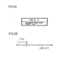
- FIG. 2A shows the structure of the subject vehicle position information.
- the subject vehicle position information indicates the road link ID assigned to the road link in which the subject vehicle is currently located and the distance between the road link start point and the exact point at which the subject vehicle is currently present. In the example presented in the figure, the subject vehicle is located on a road link assigned with link ID "01" at a point 10m away from the start point of the road link, as indicated in FIG. 2B .
- the map information 140 which is stored in a storage device such as a hard disk or a flash memory, includes road information and POI information.
- a storage device such as a hard disk or a flash memory
- the route search device 150 In response to a request input by the route search device 150 indicating a specific map area, the road information and the POI information for the particular map area are provided to the route search device 150.
- FIG. 3 shows the structure of the route search device 150.
- the route search device 150 includes a route calculation device 230, a charging station search device 240 and a waypoint calculation device 250.
- the destination information provided via the input device 110, the subject vehicle position information provided from the subject vehicle position acquisition device 130, the road information and the POI information extracted from the map information 140, and remaining battery power information provided from the battery information acquisition device 190 are input to the route search device 150.
- the route search device 150 determines through calculation a route from the current position to the destination and routes from a node present on the route to charging stations and outputs the calculation results to the route storage device 160. It also calculates a power requirement indicating the amount of power required to allow the vehicle to travel to the destination.
- the routes to the charging stations are calculated by designating a node on the route as the start point and a plurality of charging stations in the vicinity as destinations.
- a node point on the route is defined as a "waypoint” and an ith waypoint is notated as a waypoint Pi.
- the waypoint calculation device 250 designates a single charging station Ei in correspondence to the waypoint Pi.
- the route from the waypoint Pi to the charging station Ei is defined as a "guided route Li". Namely, the route from the current position to the charging station Ei is ascertained as a route passing through the waypoint Pi, which includes the guided route Li.
- the route from the current position to the waypoint Pi is part of the route from the current position to the destination.
- the route search device 150 executes the route search processing in response to a destination input via the input device 110 or in response to the subject vehicle position calculated by the subject vehicle position calculation device 120 becomes set apart from the route to the destination stored in the route storage device 160 by a distance equal to a specific value.
- the charging station information acquisition device 170 obtains, from an external provider 175, charging station position information and information indicating availability conditions at the charging stations.
- the charging station position information indicates the POI IDs assigned to the charging stations in the map information 140 and the latitudes/longitudes of the charging stations.
- the battery 180 which is a secondary battery installed in the electric vehicle, may be a lead battery or a lithium ion battery.
- the battery 180 is used to drive a motor in the electric vehicle and the like.
- the battery information acquisition device 190 measures the remaining battery power in the battery 180 by monitoring the condition of the battery 180. It provides information indicating the remaining battery power to the route search device 150 and the monitoring device 200.
- the monitoring device 200 obtains the remaining battery power information from the battery information acquisition device 190 and power requirement information indicating the amounts of power required to allow the vehicle to travel to charging stations, from the route storage device 160, monitors the electric vehicle so as to ascertain whether or not it will be able to reach the charging stations and makes a decision as to whether or not the electric vehicle should be guided to a charging station, the information pertaining to which is stored in the route storage device 160.
- the onboard terminal apparatus 100 is to guide the vehicle to the charging station Ei
- information pertaining to the charging station Ei, the waypoint Pi and the guided route Li is provided to the display device 210 and the guiding device 220.
- the monitoring device 200 repeatedly executes the processing in the flowchart presented in FIG. 11 , as described in detail later, over predetermined time intervals or predetermined traveling distance intervals by referencing the route calculation results output from the route search device 150 as described above and stored in the route storage device 160.
- the route search results are read out by the monitoring device 200 from the route storage device 160, guided routes to charging stations in the vicinity and the corresponding power requirement information are displayed.
- the guiding device 220 guides the vehicle to a specific charging station based upon the decision-making results obtained from the monitoring device 200. It guides the vehicle by displaying the guided route to the particular charging station on a map at the display device 210 and guiding the user to the charging station with voice instructions.
- map information 140 The structures of the map information 140, the route search device 150, the monitoring device 200 and the display device 210 are described next.
- FIGS. 4A, 4B, 4C and 4D each present a diagram pertaining to a structural aspect of the map information 140.
- FIG. 4A shows the structure of road data contained in the map information 140.
- the road data are compiled in units of links each extending from one node to another node.
- Each set of road data includes a link ID with which the corresponding road can be identified, a mesh ID enabling identification of the mesh in which the particular road link is located, a node ID assigned to the node at the starting end of the road link and latitude information, longitude information and altitude information indicating the latitude, the longitude and the altitude of the starting end node, a node ID assigned to the node at the terminating end of the road link and latitude information, longitude information and altitude information indicating the latitude, longitude and the altitude of the terminating end node, and traffic control information.
- the traffic control information includes speed limit information, one-way traffic information and the like.
- an interpolation point is set on a link extending between two nodes, a sub link extending between a node and the interpolation point or between two interpolation points may be defined.
- the height of the road link may be indicated in gradient information instead of the altitude information indicating the altitudes at the starting end node and the terminating end node.
- mesh data in a secondary mesh are a block of data defined by 5 min of latitude and 7 min 30 sec of longitude with each side of the mesh representing a range of approximately 10 km.
- Tertiary meshes are blocks formed by dividing the secondary mesh into 10 equal parts both along the latitudinal direction and along the longitudinal direction. Each tertiary mesh is defined by 30 sec of latitude and 45 sec of longitude, with each side thereof representing a range of approximately 1 km.
- Meshes can each be identified by a mesh ID.
- FIG. 4B shows the structure of the POI information included in the map information 140.
- Each set of POI information includes the POI ID assigned to the particular POI, the POI title, the category to which the POI belongs, the mesh ID assigned to the mesh where the POI is located, latitude information and longitude information, and road link ID of a road link adjacent to the POI.
- the POI title is the name inherent to the POI, under which the POI will be displayed at the display device 111.
- the category is a specific facility category to which the POI belongs. For instance, "1" may indicate a charging station, "2" may indicate a convenience store and "3" may indicate a gas station.
- the adjacent road link ID, with which the POI can be connected to a road link is used for purposes of route search. When executing a route search, the adjacent road link ID is extracted from the POI information for the POI set as the destination and searching for a route to the extracted road link. The route search for a route to the POI designated as the destination
- FIG. 4C shows a mesh management table.
- the mesh ID assigned to each mesh and the coordinates of the four vertices of the mesh i.e., the coordinates (latitudes and longitudes) of the lower left vertex, the upper left vertex, the lower right vertex and the upper right vertex, are stored (see FIG. 4D ).
- the flow of the processing executed by the route search device 150 is described.
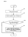
- the internal processing by the route search device 150 shown in FIG. 3 is executed as shown in the flowchart in FIG. 5 .
- the route search device 150 obtains the destination information from the input device 110, the subject vehicle position information from the subject vehicle position calculation device 130 and road information pertaining to a surrounding area included in the map information 140 (step S001).
- the processing in step S001 is executed by the route calculation device 230.
- Map areas that may be requested are all managed based upon a mesh ID list in the map information 140.
- a group of meshes that are requested include all the meshes present in a rectangular range, the diagonal of which connects the mesh where the destination is located and the mesh where the subject vehicle is currently located.
- FIG. 6 illustrates the processing executed in step S001.
- a minimum-cost route through which the vehicle will travel from the subject vehicle position ascertained via the subject vehicle position calculation device 130 to the destination set via the input device 110 with the minimum cost, is calculated (step S002).
- the processing in step S002 is executed by the route calculation device 230.
- the route having the least cost calculated by using the Dijkstra algorithm of the known art, is designated as the minimum-cost route.
- the cost may represent, for instance, the route distance (traveling distance), the required traveling time or the power requirement.
- the route data pertaining to the route thus calculated are stored into the route storage device 160.
- step S0025 the power requirement indicating the amount of power required to allow the vehicle to travel through the route is calculated and a decision is made as to whether or not the vehicle will be able to reach the destination on the current remaining battery power. If it is decided that the vehicle will not be able to reach the destination, the flow of this processing ends and a route search is executed again through a technology of the known art to determine a route that includes a stopover at a nearby charging station.
- the power requirement is also calculated by adopting a technology of the known art. It is assumed that the power requirement for a given road link is dependent upon the speed at which the road link is traveled and the gradient of the road link.
- the speed information and the road gradient information can be obtained from the map information 140.
- the power requirement W for the road link can be determined as expressed in (1) below based upon an average speed v with which vehicles travel through the road link and a gradient ⁇ of the road link.
- the speed used in this calculation may be ascertained based upon real-time traffic information or statistical traffic information compiled by accumulating traffic information and statistically processing the accumulated traffic information.
- the power requirement is ascertained as expressed in (1) for each of the link strings making up the route calculated in step S002 and the sum of the power requirements thus calculated is designated as an overall power requirement for the entire route.
- FIG. 7A shows the structure of route data and FIG. 7B presents an example of a route.
- the route data indicate the route type, the route distance, the required traveling time, the power requirement, the number of road links constituting the route, the road link IDs assigned to the individual road links, the mesh ID assigned to the mesh in which each road link is located, the start point node ID assigned to the start point node of the particular road link, the end point node ID assigned to the end point node of the road link and the power requirement indicating the amount of power required to travel through the road link.
- step S0025 If it is decided in step S0025 that the vehicle will be able to reach the destination, waypoints are calculated based upon the POI information pertaining to charging stations located near the calculated route, which is obtained from the map data, so as to determine guided routes and the power requirements for traveling through the guided routes (step S003).
- the processing in step S003 is executed by the charging station search device 240 and the waypoint calculation device 250.
- the processing in step S003 must be executed in advance so as to enable execution of the processing shown in FIG. 11 , as described in detail later, in case the subject vehicle is judged to be no longer able to reach the destination due to sudden traffic congestion or the like occurring after it has been initially decided in step S0025 that the vehicle would be able to reach the destination on the remaining battery power.
- the processing flow ends.
- step S003 the processing executed in step S003 by the charging station search device 240 and the waypoint calculation device 250 is described in detail.
- step S003-1 a decision is made as to whether or not the processing has been executed for all the nodes contained in the route by referencing the route storage device 160 (step S003-1).
- all the nodes present in the route are sequentially processed, either starting from the start point toward the destination or from the destination toward the start point. If it is decided that all the nodes have not been processed yet (No in step S003-1), information pertaining to all the charging stations located within a circle centered on a node on the route and having a predetermined radius, is obtained (step S003-2).
- the distance representing the radius of the circle may be determined in correspondence to the battery power available at the particular node on the route. For instance, if the available battery power at the node on the route is 50 percent of the maximum capacity, the distance representing the radius of the circle defining the search range and centered on the node on the route may be set to half the distance corresponding to the maximum battery power.
- the battery power available at the node on the route can be ascertained originating from the battery information acquisition device 190, which is obtained by the charging station search device 240 via the route calculation device 230, and also based upon a power requirement calculated to determine the amount of battery power required to allow the vehicle to travel from the start point to the node on the route.
- the processing in step S003-2 is executed by the waypoint calculation device 250.
- step S003-3 a decision is made as to whether or not all the charging stations have been processed. If it is decided that all the charging stations have not been processed yet (No in step S003-3), a route search is executed to calculate a route from the target node to any yet-to-be processed charging station within the circle set in correspondence to the target node, the traveling distance to the charging station and the corresponding power requirement (step S003-4). The route search is executed based upon the Dijkstra algorithm of the known art.
- the charging station with the minimum cost e.g., the charging station within the shortest traveling distance from the target node, among the charging stations having undergone the processing, is selected (step S003-5).
- a single charging station among the plurality of charging stations located in the vicinity of the node is extracted.
- the charging station located within the minimum traveling distance is ascertained by first executing a route search to determine the routes from the calculation target node to the individual charging stations.
- the traveling distances and the power requirements are calculated for the individual routes.
- the power requirements can each be calculated as expressed in (1).
- the charging station with the shortest traveling distance calculated for its route, among the plurality of charging stations, is extracted.
- the charging station with the smallest power requirement among the plurality of charging stations may be extracted as the minimum cost charging station. Through this processing, a single charging station is selected in correspondence to a given node. Once the charging station located within the minimum traveling distance is selected, the operation proceeds to step S003-1.
- step S003-1 If it is decided that all the nodes have been processed (Yes in step S003-1), a waypoint and a guided route are determined for each of the plurality of charging stations having been extracted by handling any multiple charging stations sharing a single POI ID as one charging station (step S003-6).
- the node corresponding to each charging station is defined as a waypoint.
- the route to each charging station designated as a calculation-target charging station in step S003-4 is defined as a "guided route”.
- guided route data calculated in correspondence to each waypoint are stored into the route storage device 160 (step S003-7). The guided route data calculated in correspondence to the individual waypoints will be described in detail later.
- FIG. 9A presents an example of the guided route data calculated in correspondence to each waypoint
- FIG. 9B presents an example of a guided route.
- Guided route data include the POI ID assigned to the charging station corresponding to the particular waypoint, the traveling distance over which the guided route extends, the required traveling time, the power requirement indicating the amount of power required to allow the vehicle to travel through the guided route, the node ID of the waypoint, the number of road links constituting the guided route, and the road link data pertaining to the road links constituting the guided route.
- Each set of road link data includes the mesh ID assigned to the mesh in which the corresponding road link is located, the node ID assigned to the start point node, the node ID assigned to the end point node, the link ID of the road link and the power requirement corresponding to the particular road link.
- the processing described above is executed by the route search device 150 during a route search.
- the monitoring device 200 repeatedly executes the processing to be described later in reference to the flowchart presented in FIG. 11 , over predetermined time intervals or each time the subject vehicle has traveled over a predetermined distance, by referencing the results of the processing executed by the route search device 150, which are stored in the route storage device 160.
- the monitoring device 200 creates a waypoint management table based upon the information on the waypoints Pi and the charging stations Ei, obtained from the route search device 150, and makes a decision by referencing the table as to whether or not to guide the subject vehicle to a charging station.
- the waypoint management table is stored in an internal storage device within the monitoring device 200.
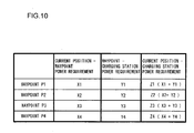
- FIG. 10 shows the structure of the waypoint management table.
- the waypoint management table, with the data therein managed in correspondence to each waypoint, is configured with three columns, i.e., a "current position-waypoint power requirement" column, a "waypoint-charging station power requirement” column and a "current position-charging station power requirement” column.
- the values (Xi) entered in the "current position-waypoint power requirement" column are each determined when the subject vehicle position is updated by calculating the sum of power requirements corresponding to the road links that include the road link in which the subject vehicle is currently located in the road link in which the waypoint Pi is located and all the road links present between them on the route to the destination stored in the route storage device 160.
- the link ID of the road link where the subject vehicle is currently located and the distance between the start point of the road link and the current subject vehicle position are obtained first from the subject vehicle position calculation device 130.
- the letter A represents the sum of the power requirements. However, the power requirement sum A is calculated by assuming that the subject vehicle is located at the start point of the road link. Accordingly, an excess power requirement A' is calculated. The excess power requirement A' is calculated as expressed in (1) based upon the link ID and the distance having already been obtained from the subject vehicle position calculation device 130. The ultimate power requirement (A - A') is then calculated and entered in the "current position-waypoint power requirement" column (Xi).
- the value indicating the power requirement for covering the distance between each waypoint Pi and the corresponding charging station Ei, stored in the route storage device 160, is directly entered as Yi in the "waypoint-charging station power requirement" column.
- the values Zi entered in the "current position-charging station power requirement” column each represent the power requirement for the subject vehicle to travel from the current position to a specific charging station Ei via the corresponding waypoint Pi, and are each calculated as the sum of the corresponding value entered in the "current position-waypoint power requirement” column and the corresponding value entered in the "waypoint-charging station power requirement” column.
- the monitoring device 200 compares the values entered in the "current position-charging station power requirement” column with the remaining battery power obtained from the battery information acquisition device 190.
- the flow of the processing executed by the monitoring device 200 is described in reference to FIG. 11 .
- the flowchart shows the internal processing executed in the monitoring device 200.
- the remaining battery power available for the electric vehicle is first obtained from the battery information acquisition device 190 (step S101).
- the remaining battery power information thus obtained is compared with the power requirements that will allow the vehicle to travel to the charging stations, to be calculated in a step following step S101.
- the subject vehicle position information is obtained from the subject vehicle position calculation device 130, the waypoint information is obtained from the route storage device 160 and the information entered in the waypoint management table is updated (step S102). Since fixed values obtained from the route information storage device 160 are entered in the "waypoint-charging station power requirement" column, the values entered in the "current position-waypoint power requirement” column and the values entered in the "current position-charging station power requirement” column alone are updated in this step.
- step S1025 a decision is made as to whether or not the vehicle will be able to reach the destination with the remaining battery power currently available in the vehicle based upon the remaining battery power information having been obtained in step S101 and the information in the waypoint management table having been updated in step S102. If it is decided that the vehicle will not be able to reach the destination, a decision is made as to which charging station the vehicle should head for (step S103) based upon the values in the "current position-charging station power requirement" column in the waypoint management table having been updated in step S102 and the electric vehicle remaining battery power information having been obtained in step S101. If it is decided, on the other hand, that the vehicle will be able to reach the destination on the remaining battery power, the processing in step S103 is skipped.
- step S 103 the power requirement (Zi) is compared with the remaining battery power in correspondence to each waypoint. It is to be noted that the remaining battery power is actually compared with a value Zi' obtained by multiplying the power requirement Zi by a safety factor k as expressed in (2) below, instead of comparing the remaining battery power with the power requirement Zi.
- Zi ⁇ k ⁇ Zi
- the safety factor k in expression (2) should be set to a value greater than 1, so as to reduce the risk of failure to reach the charging station.
- the optimal charging station is selected by making a decision as to whether or not the vehicle will be able to reach the individual charging stations each corresponding to a specific waypoint. As long as Zi' ⁇ A is true for the power requirement A calculated based upon the remaining battery power, the vehicle will be able to reach the corresponding charging station Ei, whereas if Zi' > A is true, the vehicle will not be able to reach the charging station Ei.
- the charging station reachability OK/NG table includes a "current position-charging station power requirement” column, a "reachability OK/NG” column and a "remaining battery power upon arrival” column.
- a value "1" entered in the reachability OK/NG column indicates "OK", i.e., that the vehicle will be able to reach the corresponding charging station, whereas a value "0” indicates "NG", i.e., that the vehicle will not be able to reach the corresponding charging station.
- the monitoring device 200 issues a command for the guiding device 220 (step S103) so as to guide the subject vehicle to the single charging station within the range of the vehicle once the number of charging stations that can be reached is reduced to 1, and then ends the processing flow.
- the monitoring device 200 may issue a command for the guiding device 220 so as to guide the subject vehicle to the charging station with the highest level of remaining battery power upon arrival once the number of charging stations that can be reached becomes equal to or smaller than a predetermined value.
- the monitoring device 200 may issue a command for the guiding device 220 so as to guide the subject vehicle to the charging station with the highest level of remaining battery power on arrival when the number of charging stations with their remaining battery power on arrival values equal to or less than a predetermined value becomes equal to or smaller than a specific value. While the processing flow immediately ends if it is decided in step S1025 that the vehicle will be able to reach the destination in this embodiment, the command issued to the guiding device 220 may instead be canceled upon deciding that the subject vehicle will be able to reach the destination.
- the monitoring device 200 reduces the risk of the subject vehicle failing to reach a charging station and ensures that the user will be able to travel on the recommended route with peace of mind by constantly monitoring the vehicle to ascertain whether or not the subject vehicle will be able to reach charging stations en route.
- the display device 210 references the route storage device 160 and provides the user with information indicating the power requirements for reaching nearby charging stations together with the route brought up on display in a simple display mode.
- FIGS. 13A and 13B each present an example of such a screen display.
- FIG. 13A shows a display of the route to the destination provided in the simple display mode in combination with information indicating the distances to nearby charging stations present along the route and the corresponding power requirements, which may be brought up upon completing the route search for the optimal route to the destination.
- the power requirement values indicating the amounts of power required to allow the vehicle to travel the charging stations brought up on display match the values in the "current position-charging station power requirement" column in the charging station reachability OK/NG table shown in FIG. 12 .
- FIG. 12 shows a display of the route to the destination provided in the simple display mode in combination with information indicating the distances to nearby charging stations present along the route and the corresponding power requirements, which may be brought up upon completing the route search for the optimal route to the destination.
- 13B shows a display that may be brought up as the monitoring device 200 decides that the subject vehicle will not be able to reach charging stations 2 and 3 while the vehicle advances on the route toward the destination.
- the information corresponding to the two charging stations 2 and 3 is displayed by using dotted lines, so as to distinguish it from the information pertaining to the charging station 1 located within the vehicle range.
- the present invention is not limited to this example and display of icons for charging stations that cannot be reached may be grayed out, while display of icons for charging stations that can be reached may flash or be displayed in a larger size, so as to highlight the information for charging stations within the vehicle range.
- the user may select, via an input unit such as a touch panel, the charging station to which he wishes to be guided based upon the lengths of the guided routes and the power requirements corresponding to the individual charging stations. Furthermore, instead of displaying the route to the destination in the simple display mode, the route may be displayed on the actual map.
- the display device 210 may display information indicating the availability conditions of the individual charging stations, obtained from an external source, as shown in FIGS. 14A and 14B .
- the user will select a charging station by referencing the information on display.
- FIG. 14A presents an example of a display of charging station availability conditions.
- the availability condition information is obtained from an external operation management center responsible for managing charging station availability conditions.
- FIG. 14B presents an example of a display that may be brought up to guide the subject vehicle to charging station 2 selected by the user via the input device 110 such as a touch panel.
- the onboard terminal apparatus may suggest, via the display device 210, the charging station with the shortest wait time, based upon the charging station availability conditions, so as to allow the user to choose whether or not to head for the particular charging station.
- FIG. 15 presents an example of an inquiry screen display that may be brought up by the onboard terminal apparatus having determined that charging station 2 has the least wait time for the charging service and is, therefore, the recommended charging station.
- the user is provided with options of accepting or not accepting guidance to the recommended charging station.
- the charging station with the lowest charging service fee or a charging station indicated in the previous record to be a frequently patronized charging station may be selected as the recommended charging station.
- the onboard terminal apparatus 100 achieved in the first embodiment determines in advance candidates for charging stations that the vehicle may visit, together with the guided routes to the charging stations.
- the vehicle traveling on a route determined through a search, can be guided to a charging station with a minimum route calculation load on the onboard terminal and a minimum risk of battery depletion occurring before the vehicle reaches a charging station.
- the user will not experience any confusion since the display of the routes to the charging stations does not change even as the subject vehicle position changes.
- the route planning system is achieved as a route search system in the second embodiment.
- the route search system in the embodiment includes an onboard terminal apparatus 100 shown in FIG. 16A and a center apparatus 300 shown in FIG. 16B .
- the onboard terminal apparatus 100 comprises an input device 110, a subject vehicle position calculation device 130, map information 140, a route storage device 160, a charging station information acquisition device 170, a battery information acquisition device 190, a monitoring device 200, a display device 210, a guiding device 220 and a communication device 310.
- the center apparatus 300 includes map information 140, a route search device 150, a route storage device 160 and a communication device 310.
- the onboard terminal apparatus 100 and the center apparatus 300 are connected with each other through communication achieved via the communication devices 310.
- the communication devices 310 may each be constituted with, for instance, a portable telephone, a wireless LAN module, a PDA (personal digital assistant) unit or a modem constituting an integrated part of the onboard terminal apparatus 100.
- This configuration in which the center apparatus 300 executes route search processing via its route search device 150, reduces the processing load on the onboard terminal 100 during the route search.
- Information indicating the route to the destination and the guided routes to charging stations, calculated at the center apparatus 300, is transmitted to the onboard terminal apparatus 100 via the communication device 310 at the center apparatus 300.
- the onboard terminal apparatus 100 transmits via its communication device 310, the destination information entered via the input device 110, the position information provided from the subject vehicle position calculation device 130 and the remaining battery power information provided from the battery information acquisition device 190, to the center apparatus 300.
- the information received by the communication device 310 at the center apparatus 300 is then input to the route search device 150.
- Route search results output by the route search device 150 at the center apparatus 300 are transmitted via the communication device 310 to the onboard terminal apparatus 100.
- Information indicating the route search results i.e., the route to the destination and the guided routes to the charging stations, is received by the communication device 310 of the onboard terminal apparatus 100.
- the route search results are provided to the user as they are brought up on display at the display device 210.
- monitoring device 200 and other devices assigned with the same reference numerals as those in FIG. 1 execute processing identical to that described in reference to the first embodiment, a repeated explanation is not provided.
Landscapes
- Engineering & Computer Science (AREA)
- Radar, Positioning & Navigation (AREA)
- Remote Sensing (AREA)
- Automation & Control Theory (AREA)
- Physics & Mathematics (AREA)
- General Physics & Mathematics (AREA)
- Power Engineering (AREA)
- Transportation (AREA)
- Mechanical Engineering (AREA)
- Life Sciences & Earth Sciences (AREA)
- Sustainable Development (AREA)
- Sustainable Energy (AREA)
- Navigation (AREA)
- Electric Propulsion And Braking For Vehicles (AREA)
Applications Claiming Priority (1)
| Application Number | Priority Date | Filing Date | Title |
|---|---|---|---|
| JP2010052122A JP5017398B2 (ja) | 2010-03-09 | 2010-03-09 | 経路計画装置及び経路計画システム |
Publications (3)
| Publication Number | Publication Date |
|---|---|
| EP2365285A2 true EP2365285A2 (fr) | 2011-09-14 |
| EP2365285A3 EP2365285A3 (fr) | 2014-11-19 |
| EP2365285B1 EP2365285B1 (fr) | 2015-09-09 |
Family
ID=44117251
Family Applications (1)
| Application Number | Title | Priority Date | Filing Date |
|---|---|---|---|
| EP11155549.6A Active EP2365285B1 (fr) | 2010-03-09 | 2011-02-23 | Dispositif de programmation d'itinéraires et système de programmation d'itinéraires |
Country Status (4)
| Country | Link |
|---|---|
| US (1) | US8751077B2 (fr) |
| EP (1) | EP2365285B1 (fr) |
| JP (1) | JP5017398B2 (fr) |
| CN (1) | CN102192755B (fr) |
Cited By (13)
| Publication number | Priority date | Publication date | Assignee | Title |
|---|---|---|---|---|
| DE102011106612A1 (de) * | 2011-06-16 | 2012-12-20 | Navigon Ag | Multihop-Routing |
| EP2578997A1 (fr) * | 2011-10-07 | 2013-04-10 | Hitachi, Ltd. | Système de support d'utilisateur d'un véhicule à propulsion électrique |
| EP2752810A4 (fr) * | 2011-09-16 | 2015-12-09 | Mitsubishi Heavy Ind Ltd | Système de gestion de chargeurs de bureau, procédé de commande et programme |
| EP2858058A4 (fr) * | 2012-05-31 | 2016-01-13 | Nec Corp | Système et procédé de traitement d'informations, terminal de communication mobile, procédé et programme de commande de terminal de communication mobile, serveur et son procédé et programme de commande |
| EP2894436A4 (fr) * | 2012-09-03 | 2016-04-27 | Hitachi Ltd | Système d'aide au chargement et procédé d'aide au chargement destinés à un véhicule électrique |
| EP2907689A4 (fr) * | 2012-10-15 | 2016-07-27 | Sk Planet Co Ltd | Système et procédé permettant de gérer un véhicule électrique |
| EP2573520A3 (fr) * | 2011-09-22 | 2017-12-20 | Hitachi, Ltd. | Système permettant de fournir des informations sur la quantité de consommation d'énergie d'un véhicule électrique |
| EP3556601A1 (fr) * | 2018-04-16 | 2019-10-23 | Morgan Brown Consultancy Ltd. | Routage de véhicule |
| CN110493305A (zh) * | 2019-07-05 | 2019-11-22 | 广州车行易科技股份有限公司 | 一种根据充电站使用状况和距离远近来进行充电路径规划的方法 |
| CN111391712A (zh) * | 2020-04-30 | 2020-07-10 | 青岛特来电新能源科技有限公司 | 一种充电管理方法、装置、设备及计算机可读存储介质 |
| EP3772429A1 (fr) * | 2019-08-08 | 2021-02-10 | Ningbo Geely Automobile Research & Development Co., Ltd. | Procédé de commande d'un système d'avertissement à faible carburant ou faible charge dans un véhicule |
| CN112414423A (zh) * | 2020-11-20 | 2021-02-26 | 腾讯科技(深圳)有限公司 | 车导起点道路的规划方法、装置、电子设备及存储介质 |
| CN113386770A (zh) * | 2021-06-10 | 2021-09-14 | 武汉理工大学 | 基于充电站数据共享的电动汽车充电路径动态规划方法 |
Families Citing this family (146)
| Publication number | Priority date | Publication date | Assignee | Title |
|---|---|---|---|---|
| WO2010137307A1 (fr) * | 2009-05-26 | 2010-12-02 | 日立オートモティブシステムズ株式会社 | Système de support de fonctionnement de véhicule et procédé |
| WO2011092729A1 (fr) * | 2010-01-26 | 2011-08-04 | 三菱電機株式会社 | Appareil de navigation, appareil d'affichage des informations du véhicule et système d'affichage des informations du véhicule |
| US20120143410A1 (en) * | 2010-12-01 | 2012-06-07 | Aptera Motors, Inc. | Interactive driver system for an electric vehicle |
| US20150191097A1 (en) * | 2010-12-24 | 2015-07-09 | Martin Kelly Jones | Determinig sufficiency of electric power capacity (epc) for user defined travel itinerary of electric powered mobile thing (epmt) |
| WO2012092518A1 (fr) * | 2010-12-30 | 2012-07-05 | Telenav, Inc. | Système de navigation à mécanisme de planification d'itinéraire à ressources restreintes et son procédé d'exploitation |
| US8755994B2 (en) * | 2011-01-06 | 2014-06-17 | Ford Global Technologies, Llc | Information display system and method |
| US10217160B2 (en) | 2012-04-22 | 2019-02-26 | Emerging Automotive, Llc | Methods and systems for processing charge availability and route paths for obtaining charge for electric vehicles |
| US9285944B1 (en) | 2011-04-22 | 2016-03-15 | Angel A. Penilla | Methods and systems for defining custom vehicle user interface configurations and cloud services for managing applications for the user interface and learned setting functions |
| US9123035B2 (en) | 2011-04-22 | 2015-09-01 | Angel A. Penilla | Electric vehicle (EV) range extending charge systems, distributed networks of charge kiosks, and charge locating mobile apps |
| US10065628B2 (en) * | 2011-05-09 | 2018-09-04 | Ford Global Technologies, Llc | Location enhanced distance until charge (DUC) estimation for a plug-in hybrid electric vehicle (PHEV) |
| DE102011108381B4 (de) * | 2011-07-22 | 2013-02-21 | Audi Ag | Verfahren zum Unterstützen einer Person beim Planen einer Fahrt mit einem Elektrofahrzeug und Kraftfahrzeug mit einer Navigationseinrichtung |
| WO2013016570A1 (fr) | 2011-07-26 | 2013-01-31 | Gogoro, Inc. | Appareil, procédé et article utilisés pour l'authentification, la sécurité et le contrôle de dispositifs de stockage d'energie, tels que des accumulateurs, sur la base de profils d'utilisateur |
| US9552682B2 (en) | 2011-07-26 | 2017-01-24 | Gogoro Inc. | Apparatus, method and article for redistributing power storage devices, such as batteries, between collection, charging and distribution machines |
| US10186094B2 (en) | 2011-07-26 | 2019-01-22 | Gogoro Inc. | Apparatus, method and article for providing locations of power storage device collection, charging and distribution machines |
| EP2736760A4 (fr) | 2011-07-26 | 2015-11-04 | Gogoro Inc | Limitation dynamique du fonctionnement d'un véhicule permettant de réaliser la meilleure économie possible |
| JP6096773B2 (ja) | 2011-07-26 | 2017-03-15 | ゴゴロ インク | 電池などの電力貯蔵装置の認証、セキュリティ、及び制御用の装置、方法、及び物品 |
| WO2013016564A2 (fr) | 2011-07-26 | 2013-01-31 | Gogoro, Inc. | Appareil, procédé et article permettant de reserver des dispositifs de stockage de puissance au niveau de machines de collecte, de charge et de distribution de dispositifs de stockage de puissance |
| JP5758051B2 (ja) | 2011-07-26 | 2015-08-05 | ゴゴロ インク | 車両の電力蓄積デバイスを物理的に保障する装置、方法、および物品 |
| ES2692524T3 (es) | 2011-07-26 | 2018-12-04 | Gogoro Inc. | Aparato, método y artículo para proporcionar datos de diagnóstico de vehículo |
| TWI517078B (zh) | 2011-07-26 | 2016-01-11 | 睿能創意公司 | 用於電力儲存器件收容空間之裝置、方法及物品 |
| JP5960260B2 (ja) | 2011-07-26 | 2016-08-02 | ゴゴロ インク | 電力蓄積デバイスの収集、充電、および分配マシンの場所を提供するための装置、方法、および物品 |
| CN103875155B (zh) | 2011-07-26 | 2017-07-07 | 睿能创意公司 | 用于收集、充电和分配如电池之类的电力存储设备的装置、方法及物品 |
| ES2748199T3 (es) | 2011-07-26 | 2020-03-13 | Gogoro Inc | Aparato, método y artículo para proporcionar información sobre la disponibilidad de dispositivos de almacenamiento de energía en una máquina de recogida, carga y distribución de dispositivos de almacenamiento de energía |
| KR101270116B1 (ko) * | 2011-11-09 | 2013-05-31 | 자동차부품연구원 | 전기자동차의 주행 가능 거리 추정 시스템 및 그 방법 |
| TWI462847B (zh) * | 2011-11-30 | 2014-12-01 | Automotive Res & Testing Ct | Method of Recursive Path Planning for Electric Vehicles |
| CN103148860B (zh) * | 2011-12-06 | 2016-01-20 | 财团法人车辆研究测试中心 | 电动车递归式路径规划方法 |
| GB2497981B (en) * | 2011-12-23 | 2013-11-13 | Charles Linfield Davies | Generating travel time data |
| US8965669B2 (en) | 2012-01-09 | 2015-02-24 | Airbiquity Inc. | Electric vehicle charging network services |
| JP5903905B2 (ja) * | 2012-01-25 | 2016-04-13 | 三菱自動車工業株式会社 | ナビゲーション装置 |
| KR101355989B1 (ko) | 2012-02-06 | 2014-01-29 | 한국과학기술원 | 최적 운행 정보 결정 방법 및 장치 |
| EP2631595A1 (fr) * | 2012-02-22 | 2013-08-28 | Harman Becker Automotive Systems GmbH | Système de navigation et procédé de fonctionnement d'un véhicule électrique |
| JP5835024B2 (ja) * | 2012-03-07 | 2015-12-24 | 株式会社デンソー | 充電ポイント通知システムおよび車両側装置 |
| JP5835023B2 (ja) * | 2012-03-07 | 2015-12-24 | 株式会社デンソー | 充電ポイント到達判定システムおよび車両側装置 |
| US9796280B2 (en) | 2012-03-23 | 2017-10-24 | Hevo Inc. | Systems and mobile application for electric wireless charging stations |
| JP5815843B2 (ja) * | 2012-03-30 | 2015-11-17 | パイオニア株式会社 | 画像処理装置、画像処理管理装置、端末装置及び画像処理方法 |
| WO2013145265A1 (fr) * | 2012-03-30 | 2013-10-03 | パイオニア株式会社 | Dispositif de recherche, dispositif de gestion de recherche, dispositif terminal et méthode de calcul |
| DE102012210103A1 (de) * | 2012-06-15 | 2013-12-19 | Robert Bosch Gmbh | Reichweitenbestimmung für ein Kraftfahrzeug |
| DE102012210698A1 (de) * | 2012-06-25 | 2014-01-02 | Robert Bosch Gmbh | Verfahren zum Durchführen eines Energiemanagements eines Fahrzeuges |
| JP6035917B2 (ja) | 2012-07-05 | 2016-11-30 | 日産自動車株式会社 | 車両用情報提供装置 |
| KR101385371B1 (ko) * | 2012-07-11 | 2014-04-14 | 제주대학교 산학협력단 | 대기 시간을 이용한 전기 자동차의 경로 스케쥴링 방법 및 시스템 |
| US9302594B2 (en) * | 2012-07-31 | 2016-04-05 | Qualcomm Incorporated | Selective communication based on distance from a plurality of electric vehicle wireless charging stations in a facility |
| JP5929602B2 (ja) * | 2012-08-02 | 2016-06-08 | 株式会社デンソー | ナビゲーション装置 |
| US9407105B2 (en) * | 2012-09-24 | 2016-08-02 | Elwha Llc | Systems and methods for transferring electrical energy between vehicles |
| CN103715725B (zh) * | 2012-09-29 | 2017-03-01 | 日电(中国)有限公司 | 电动车充电系统和方法 |
| EP2717016B1 (fr) | 2012-10-05 | 2020-05-20 | Hitachi, Ltd. | Procédé et système permettant de fournir une assistance de route pour véhicules électriques |
| KR101417401B1 (ko) * | 2012-11-12 | 2014-07-08 | 현대자동차주식회사 | 전기자동차의 주행가능 거리 안내 장치 및 그 방법 |
| WO2014078557A1 (fr) | 2012-11-16 | 2014-05-22 | Gogoro, Inc. | Appareil, procédé et article pour clignotants de véhicule |
| CN102914311A (zh) * | 2012-11-19 | 2013-02-06 | 上海梦擎信息科技有限公司 | 加油提醒服务系统和方法 |
| CN103020734A (zh) * | 2012-12-04 | 2013-04-03 | 北京世纪高通科技有限公司 | 换乘路径计算方法及装置 |
| CN103868518B (zh) * | 2012-12-13 | 2017-04-12 | 华创车电技术中心股份有限公司 | 电动交通载具的导航路径规划方法 |
| KR101449170B1 (ko) * | 2012-12-17 | 2014-10-10 | 현대자동차주식회사 | 전기자동차의 충전소 안내 시스템 및 그 방법 |
| CN103236179B (zh) * | 2012-12-18 | 2015-04-15 | 清华大学 | 一种计及交通信息与电网信息的电动汽车充电导航方法 |
| TWI500538B (zh) * | 2012-12-19 | 2015-09-21 | Inventec Corp | 電動車輛充電監控之車用裝置及其方法 |
| JP6020150B2 (ja) * | 2012-12-27 | 2016-11-02 | 日産自動車株式会社 | 車両用情報提供装置 |
| JP6020149B2 (ja) | 2012-12-27 | 2016-11-02 | 日産自動車株式会社 | 車両用情報提供装置 |
| JP6044330B2 (ja) | 2012-12-27 | 2016-12-14 | 日産自動車株式会社 | 車両用情報提供装置 |
| JP6020151B2 (ja) | 2012-12-27 | 2016-11-02 | 日産自動車株式会社 | 車両用情報提供装置 |
| US9098386B1 (en) * | 2012-12-31 | 2015-08-04 | Amdocs Software Systems Limited | System, method, and computer program for determining a subjective distance between two locations |
| US9854438B2 (en) | 2013-03-06 | 2017-12-26 | Gogoro Inc. | Apparatus, method and article for authentication, security and control of portable charging devices and power storage devices, such as batteries |
| US11222485B2 (en) | 2013-03-12 | 2022-01-11 | Gogoro Inc. | Apparatus, method and article for providing information regarding a vehicle via a mobile device |
| EP2973941A4 (fr) | 2013-03-12 | 2016-09-14 | Gogoro Inc | Appareil, procédé et article conçus pour modifier les plans d'échange de dispositif portatif de stockage d'énergie électrique |
| US9122567B2 (en) | 2013-03-14 | 2015-09-01 | Ford Global Technologies, Llc | User interface system and method |
| ES2802906T3 (es) | 2013-03-15 | 2021-01-21 | Gogoro Inc | Sistema modular para la recogida y distribución de dispositivos de almacenamiento eléctrico |
| EP2784446B1 (fr) * | 2013-03-26 | 2019-10-30 | Alcatel Lucent | Système de routage de trafic rapide |
| JP6268751B2 (ja) * | 2013-05-23 | 2018-01-31 | 住友電気工業株式会社 | 目的地情報提供システム及び方法、並びにコンピュータプログラム |
| WO2014207884A1 (fr) * | 2013-06-28 | 2014-12-31 | パイオニア株式会社 | Dispositif de recherche d'itinéraire, dispositif terminal et procédé de recherche d'itinéraire |
| TWI644194B (zh) | 2013-08-06 | 2018-12-11 | 睿能創意公司 | 電能儲存裝置熱分布調節控制器、方法及其電動車系統 |
| US9770996B2 (en) | 2013-08-06 | 2017-09-26 | Gogoro Inc. | Systems and methods for powering electric vehicles using a single or multiple power cells |
| JP6081902B2 (ja) | 2013-10-31 | 2017-02-15 | 三菱重工業株式会社 | 走行経路案内装置、走行経路案内システム、走行経路案内方法およびプログラム |
| US9124085B2 (en) | 2013-11-04 | 2015-09-01 | Gogoro Inc. | Apparatus, method and article for power storage device failure safety |
| TWI626183B (zh) | 2013-11-08 | 2018-06-11 | 睿能創意公司 | 用於提供車輛事件資料的裝置、方法與物品 |
| US9488493B2 (en) * | 2014-01-16 | 2016-11-08 | Ford Global Technologies, Llc | Method and apparatus for electric vehicle trip and recharge planning |
| US9837842B2 (en) | 2014-01-23 | 2017-12-05 | Gogoro Inc. | Systems and methods for utilizing an array of power storage devices, such as batteries |
| CN105960573B (zh) * | 2014-02-07 | 2020-07-24 | 日产自动车株式会社 | 车辆信息提供装置 |
| US20150226566A1 (en) * | 2014-02-07 | 2015-08-13 | Recargo, Inc. | Determining a route of travel for an electric vehicle |
| KR101574137B1 (ko) * | 2014-04-03 | 2015-12-04 | (주)진우소프트이노베이션 | 도로 기울기 변화량에 따른 배터리 소모량 가중치 알고리즘을 적용한 전기자동차 특화 내비게이션 장치 및 그 방법 |
| US20150345984A1 (en) * | 2014-05-27 | 2015-12-03 | Atieva, Inc. | Vehicle Navigation Route Optimized for EV Charging |
| JP5868454B2 (ja) * | 2014-06-09 | 2016-02-24 | 三菱電機株式会社 | 充電設備情報提供システムおよび電動車両 |
| JP6173973B2 (ja) * | 2014-06-11 | 2017-08-02 | 株式会社日立ソリューションズ | ナビゲーション装置 |
| CN104121921B (zh) * | 2014-07-01 | 2018-06-19 | 王玉娇 | 一种电动车充电导航方法、系统及相关设备 |
| TWI603552B (zh) | 2014-08-11 | 2017-10-21 | 睿能創意公司 | 多方向性的電連接器、插頭及系統 |
| ES2914287T3 (es) | 2014-09-04 | 2022-06-08 | Gogoro Inc | Módulo de carga para un sistema de distribución bidireccional de dispositivos de almacenamiento de energía eléctrica |
| USD789883S1 (en) | 2014-09-04 | 2017-06-20 | Gogoro Inc. | Collection, charging and distribution device for portable electrical energy storage devices |
| KR101634870B1 (ko) * | 2014-10-31 | 2016-06-29 | 제주대학교 산학협력단 | 충전기 선택 메카니즘을 갖는 전기 자동차의 투어 스케줄러 |
| US10309797B2 (en) * | 2014-12-19 | 2019-06-04 | Here Global B.V. | User interface for displaying navigation information in a small display |
| JP6117844B2 (ja) * | 2015-03-31 | 2017-04-19 | 本田技研工業株式会社 | サーバ、クライアントおよびシステム |
| ES2934213T3 (es) | 2015-06-05 | 2023-02-20 | Gogoro Inc | Sistemas y métodos para detección de carga de vehículo y respuesta |
| JP6597218B2 (ja) | 2015-11-17 | 2019-10-30 | オムロン株式会社 | バッテリ予約装置およびバッテリ予約方法 |
| JP6724343B2 (ja) | 2015-11-17 | 2020-07-15 | オムロン株式会社 | 予約管理装置、予約管理システムおよび予約管理方法 |
| JP6766343B2 (ja) * | 2015-11-17 | 2020-10-14 | オムロン株式会社 | バッテリ予約装置 |
| JP6582909B2 (ja) | 2015-11-17 | 2019-10-02 | オムロン株式会社 | バッテリ予約装置およびバッテリ予約方法 |
| CN105575169A (zh) * | 2015-12-30 | 2016-05-11 | 桂林众捷新能源科技有限公司 | 基于车位地图的充电管理方法及车位地图的应用 |
| US10503168B1 (en) | 2016-01-22 | 2019-12-10 | State Farm Mutual Automotive Insurance Company | Autonomous vehicle retrieval |
| US11242051B1 (en) | 2016-01-22 | 2022-02-08 | State Farm Mutual Automobile Insurance Company | Autonomous vehicle action communications |
| US11441916B1 (en) | 2016-01-22 | 2022-09-13 | State Farm Mutual Automobile Insurance Company | Autonomous vehicle trip routing |
| US11719545B2 (en) | 2016-01-22 | 2023-08-08 | Hyundai Motor Company | Autonomous vehicle component damage and salvage assessment |
| KR101865729B1 (ko) * | 2016-06-23 | 2018-06-08 | 현대자동차 주식회사 | 전기자동차 경로 안내 시스템 및 그 방법 |
| CN106218427B (zh) * | 2016-07-28 | 2018-11-20 | 百度在线网络技术(北京)有限公司 | 无人车的充电方法及装置 |
| US10180333B2 (en) * | 2016-08-12 | 2019-01-15 | Ford Global Technologies, Llc | Crowd-sourced electric vehicle charging station identification |
| JP2016206209A (ja) * | 2016-08-30 | 2016-12-08 | 三菱電機株式会社 | ナビゲーション装置およびナビゲーション方法 |
| US10369894B2 (en) * | 2016-10-21 | 2019-08-06 | Hevo, Inc. | Parking alignment sequence for wirelessly charging an electric vehicle |
| JP6520886B2 (ja) * | 2016-10-26 | 2019-05-29 | トヨタ自動車株式会社 | 車両 |
| JP6687499B2 (ja) | 2016-11-01 | 2020-04-22 | 本田技研工業株式会社 | 情報処理装置 |
| US10128697B1 (en) | 2017-05-01 | 2018-11-13 | Hevo, Inc. | Detecting and deterring foreign objects and living objects at wireless charging stations |
| JP6683175B2 (ja) * | 2017-05-17 | 2020-04-15 | トヨタ自動車株式会社 | ハイブリッド車両の制御装置 |
| DE102017215792B4 (de) * | 2017-09-07 | 2020-06-18 | Bayerische Motoren Werke Aktiengesellschaft | Verfahren, Vorrichtung, Computerprogramm und Computerprogrammprodukt zur Routenplanung für ein Fahrzeug |
| JP6922661B2 (ja) * | 2017-11-01 | 2021-08-18 | トヨタ自動車株式会社 | サーバおよび情報提供システム |
| JP6984323B2 (ja) | 2017-11-01 | 2021-12-17 | トヨタ自動車株式会社 | 情報提供システムおよびサーバ |
| CN108151753A (zh) * | 2017-12-06 | 2018-06-12 | 佛山华平勇创能源科技有限公司 | 基于电池电量的导航方法、装置、存储介质及终端 |
| JP7026208B2 (ja) * | 2018-03-28 | 2022-02-25 | 日立Astemo株式会社 | 地図提供装置 |
| US11131554B2 (en) * | 2018-12-26 | 2021-09-28 | Beijing Voyager Technology Co., Ltd. | Systems and methods for vehicle telemetry |
| US11287270B2 (en) | 2018-12-26 | 2022-03-29 | Beijing Voyager Technology Co., Ltd. | Systems and methods for safe route planning for a vehicle |
| US11397092B2 (en) * | 2019-01-03 | 2022-07-26 | International Business Machines Corporation | Determining directional guidance for vehicles |
| JP7146656B2 (ja) * | 2019-01-16 | 2022-10-04 | 株式会社ゼンリンデータコム | 端末装置、サーバ装置、プログラム |
| DE102019101094A1 (de) * | 2019-01-16 | 2020-07-16 | Bayerische Motoren Werke Aktiengesellschaft | Verfahren zur Routenplanung in einem Navigationssystem eines Fahrzeugs, Navigationssystem für ein Fahrzeug und Fahrzeug mit demselben |
| CN112512943B (zh) * | 2019-02-01 | 2023-12-08 | 松下电器(美国)知识产权公司 | 信息处理方法及信息处理系统 |
| CN110254285B (zh) * | 2019-06-28 | 2022-11-22 | 重庆长安新能源汽车科技有限公司 | 一种基于车联网的对里程焦虑用户提供服务的方法及系统 |
| US20210081863A1 (en) * | 2019-07-25 | 2021-03-18 | Airwire Technologies | Vehicle intelligent assistant |
| US12090955B2 (en) | 2019-07-29 | 2024-09-17 | Airwire Technologies | Vehicle intelligent assistant using contextual data |
| US20210049519A1 (en) * | 2019-08-13 | 2021-02-18 | Honda Motor Co., Ltd. | Electric vehicle (ev) charging station management |
| JP7222342B2 (ja) * | 2019-11-25 | 2023-02-15 | トヨタ自動車株式会社 | 充電施設案内システムおよび充電施設案内装置 |
| EP4100698A1 (fr) * | 2020-02-07 | 2022-12-14 | Bayerische Motoren Werke Aktiengesellschaft | Détermination d'itinéraire destinée à un véhicule électrique |
| US20220063440A1 (en) * | 2020-08-27 | 2022-03-03 | GM Global Technology Operations LLC | Charging systems and methods for electric vehicles |
| US12024028B2 (en) * | 2020-09-10 | 2024-07-02 | Zero Electric Vehicles Corp. | Priority based power management method for an electric motor vehicle |
| JP7338603B2 (ja) * | 2020-10-15 | 2023-09-05 | トヨタ自動車株式会社 | サーバ、移動システムおよびプログラム |
| US11634163B2 (en) | 2020-11-09 | 2023-04-25 | Toyota Motor Engineering & Manufacturing North America, Inc. | Producing, for an autonomous vehicle, a route from an origination to a destination |
| US11355003B1 (en) * | 2020-12-08 | 2022-06-07 | International Business Machines Corporation | Incident location reporting using isodistance |
| US12179624B2 (en) * | 2021-03-23 | 2024-12-31 | Honeywell International Inc. | Systems and methods for guiding vehicles to charging points |
| WO2022264379A1 (fr) * | 2021-06-17 | 2022-12-22 | 株式会社Subaru | Dispositif de fourniture d'informations |
| US12158350B2 (en) | 2021-08-11 | 2024-12-03 | Dr. Ing. H.C. F. Porsche Aktiengesellschaft | System and method for directing a driver of an electric vehicle to a point of interest and a charging station in close proximity to the point of interest |
| DE102021004631A1 (de) * | 2021-09-14 | 2023-03-16 | Mercedes-Benz Group AG | Verfahren zum Festlegen einer intelligenten Vorauswahl geeigneter Ladestationen zum Durchführen eines Ladestopps, Ladestopp-Planungsassistent und Fahrzeug |
| CN114046794B (zh) | 2021-09-27 | 2024-01-26 | 高德软件有限公司 | 路线规划方法、装置、导航方法及计算机可读存储介质 |
| CN113901321A (zh) * | 2021-10-21 | 2022-01-07 | 车主邦(北京)科技有限公司 | 一种充电推荐方法及装置 |
| KR102737095B1 (ko) * | 2021-11-29 | 2024-12-03 | 주식회사 티비유 | 추천 충전 경로를 제공하는 방법 및 이를 수행하는 충전소 정보 제공 서버, 그리고 추천 충전 경로를 제공하는 충전소 정보 제공 애플리케이션 |
| CN114548484B (zh) * | 2022-01-07 | 2023-01-24 | 国网湖北省电力有限公司黄冈供电公司 | 一种电动汽车充电站点选址规划方法 |
| US20230249581A1 (en) * | 2022-02-09 | 2023-08-10 | Nott Corporation | Methods and systems for power management of a vehicle |
| US20230342874A1 (en) * | 2022-04-25 | 2023-10-26 | Toyota Motor North America, Inc. | Prioritizing access to shared vehicles based on need |
| US12392624B2 (en) | 2022-07-11 | 2025-08-19 | The Regents Of The University Of California | Stochastic route planning for electric vehicles |
| US12188776B2 (en) | 2022-10-29 | 2025-01-07 | Volvo Car Corporation | Dynamic routing system to select charging stations |
| CN116337097A (zh) * | 2023-01-05 | 2023-06-27 | 蔚来软件科技(上海)有限公司 | 路线信息处理方法、装置和计算机设备 |
| US20240239226A1 (en) * | 2023-01-16 | 2024-07-18 | Toyota Motor North America, Inc. | Managing availability of limited charging stations |
| TWI845200B (zh) * | 2023-03-09 | 2024-06-11 | 中華電信股份有限公司 | 一種基於充電站之路徑規劃系統、方法及其電腦可讀媒介 |
| JP2024135600A (ja) * | 2023-03-23 | 2024-10-04 | トヨタ自動車株式会社 | 情報管理システム |
| TWI866298B (zh) * | 2023-06-21 | 2024-12-11 | 亞東學校財團法人亞東科技大學 | 電動車旅途電量管理系統及其方法 |
| WO2025046665A1 (fr) * | 2023-08-25 | 2025-03-06 | 本田技研工業株式会社 | Dispositif de simulation d'itinéraire et procédé de simulation d'itinéraire |
| CN117172503B (zh) * | 2023-09-21 | 2024-10-25 | 深圳云天励飞技术股份有限公司 | 新能源车电池更换调度方法、装置、电子设备及存储介质 |
Citations (2)
| Publication number | Priority date | Publication date | Assignee | Title |
|---|---|---|---|---|
| JP2003262525A (ja) | 2002-03-08 | 2003-09-19 | Nissan Motor Co Ltd | 充電スタンド情報提供装置 |
| JP2010052122A (ja) | 2008-08-29 | 2010-03-11 | Nec Personal Products Co Ltd | 作業台位置調整システム |
Family Cites Families (15)
| Publication number | Priority date | Publication date | Assignee | Title |
|---|---|---|---|---|
| DE19519107C1 (de) * | 1995-05-24 | 1996-04-04 | Daimler Benz Ag | Fahrtroutenratgebereinrichtung |
| JPH10170293A (ja) * | 1996-12-05 | 1998-06-26 | Nissan Motor Co Ltd | 電気自動車の経路探索装置 |
| JP2001215124A (ja) * | 2000-02-03 | 2001-08-10 | Fujitsu Ten Ltd | ナビゲーション装置、施設データ記憶媒体、及び施設データ提供装置 |
| JP3758140B2 (ja) * | 2001-07-09 | 2006-03-22 | 日産自動車株式会社 | 情報提示装置 |
| JP4090912B2 (ja) * | 2003-02-27 | 2008-05-28 | 三菱電機株式会社 | 車載ナビゲーション装置 |
| JP2006112932A (ja) * | 2004-10-15 | 2006-04-27 | Fuji Heavy Ind Ltd | 電気自動車のナビゲーションシステム |
| US20090234572A1 (en) * | 2005-09-28 | 2009-09-17 | Aisin Aw Co., Ltd | Surrounding Search Data Generating System, Surrounding Search System, Surrounding Search Data Generating Method, Surrounding Search Method, and Navigation Apparatus |
| JP4609312B2 (ja) * | 2005-12-27 | 2011-01-12 | アイシン・エィ・ダブリュ株式会社 | 車両制御装置 |
| JP2008039547A (ja) * | 2006-08-04 | 2008-02-21 | Matsushita Electric Ind Co Ltd | 案内装置 |
| EP2195184A4 (fr) * | 2007-09-20 | 2011-03-09 | Better Place GmbH | Réseau de véhicule électrique |
| JP4927016B2 (ja) * | 2008-03-31 | 2012-05-09 | トヨタ自動車株式会社 | ナビゲーションシステムおよびそれを備えたハイブリッド車両 |
| CN102037324B (zh) * | 2008-04-01 | 2015-05-13 | 德卡尔塔公司 | 用于提供到兴趣点的路线的方法及系统 |
| JP5120204B2 (ja) * | 2008-10-28 | 2013-01-16 | アイシン・エィ・ダブリュ株式会社 | 走行案内装置、走行案内方法及びコンピュータプログラム |
| JP4692646B2 (ja) * | 2009-02-04 | 2011-06-01 | 株式会社デンソー | 動力発生源制御装置 |
| US9079586B2 (en) * | 2011-02-17 | 2015-07-14 | Ford Global Technologies, Llc | Method and system for extending an operating range of a motor vehicle |
-
2010
- 2010-03-09 JP JP2010052122A patent/JP5017398B2/ja active Active
-
2011
- 2011-02-23 EP EP11155549.6A patent/EP2365285B1/fr active Active
- 2011-02-25 CN CN2011100482640A patent/CN102192755B/zh active Active
- 2011-02-25 US US13/034,814 patent/US8751077B2/en active Active
Patent Citations (2)
| Publication number | Priority date | Publication date | Assignee | Title |
|---|---|---|---|---|
| JP2003262525A (ja) | 2002-03-08 | 2003-09-19 | Nissan Motor Co Ltd | 充電スタンド情報提供装置 |
| JP2010052122A (ja) | 2008-08-29 | 2010-03-11 | Nec Personal Products Co Ltd | 作業台位置調整システム |
Cited By (17)
| Publication number | Priority date | Publication date | Assignee | Title |
|---|---|---|---|---|
| DE102011106612A1 (de) * | 2011-06-16 | 2012-12-20 | Navigon Ag | Multihop-Routing |
| EP2752810A4 (fr) * | 2011-09-16 | 2015-12-09 | Mitsubishi Heavy Ind Ltd | Système de gestion de chargeurs de bureau, procédé de commande et programme |
| EP2573520A3 (fr) * | 2011-09-22 | 2017-12-20 | Hitachi, Ltd. | Système permettant de fournir des informations sur la quantité de consommation d'énergie d'un véhicule électrique |
| EP2578997A1 (fr) * | 2011-10-07 | 2013-04-10 | Hitachi, Ltd. | Système de support d'utilisateur d'un véhicule à propulsion électrique |
| US8825354B2 (en) | 2011-10-07 | 2014-09-02 | Hitachi, Ltd. | System for supporting a user of an electrically driven vehicle |
| EP2858058A4 (fr) * | 2012-05-31 | 2016-01-13 | Nec Corp | Système et procédé de traitement d'informations, terminal de communication mobile, procédé et programme de commande de terminal de communication mobile, serveur et son procédé et programme de commande |
| US9506766B2 (en) | 2012-05-31 | 2016-11-29 | Nec Corporation | Techniques for providing replenishment point information |
| EP2894436A4 (fr) * | 2012-09-03 | 2016-04-27 | Hitachi Ltd | Système d'aide au chargement et procédé d'aide au chargement destinés à un véhicule électrique |
| EP2907689A4 (fr) * | 2012-10-15 | 2016-07-27 | Sk Planet Co Ltd | Système et procédé permettant de gérer un véhicule électrique |
| EP3556601A1 (fr) * | 2018-04-16 | 2019-10-23 | Morgan Brown Consultancy Ltd. | Routage de véhicule |
| CN110493305A (zh) * | 2019-07-05 | 2019-11-22 | 广州车行易科技股份有限公司 | 一种根据充电站使用状况和距离远近来进行充电路径规划的方法 |
| EP3772429A1 (fr) * | 2019-08-08 | 2021-02-10 | Ningbo Geely Automobile Research & Development Co., Ltd. | Procédé de commande d'un système d'avertissement à faible carburant ou faible charge dans un véhicule |
| CN111391712A (zh) * | 2020-04-30 | 2020-07-10 | 青岛特来电新能源科技有限公司 | 一种充电管理方法、装置、设备及计算机可读存储介质 |
| CN111391712B (zh) * | 2020-04-30 | 2022-03-08 | 青岛特来电新能源科技有限公司 | 一种充电管理方法、装置、设备及计算机可读存储介质 |
| CN112414423A (zh) * | 2020-11-20 | 2021-02-26 | 腾讯科技(深圳)有限公司 | 车导起点道路的规划方法、装置、电子设备及存储介质 |
| CN113386770A (zh) * | 2021-06-10 | 2021-09-14 | 武汉理工大学 | 基于充电站数据共享的电动汽车充电路径动态规划方法 |
| CN113386770B (zh) * | 2021-06-10 | 2024-03-26 | 武汉理工大学 | 基于充电站数据共享的电动汽车充电路径动态规划方法 |
Also Published As
| Publication number | Publication date |
|---|---|
| US20110224900A1 (en) | 2011-09-15 |
| US8751077B2 (en) | 2014-06-10 |
| JP2011185785A (ja) | 2011-09-22 |
| EP2365285B1 (fr) | 2015-09-09 |
| CN102192755B (zh) | 2013-12-25 |
| JP5017398B2 (ja) | 2012-09-05 |
| CN102192755A (zh) | 2011-09-21 |
| EP2365285A3 (fr) | 2014-11-19 |
Similar Documents
| Publication | Publication Date | Title |
|---|---|---|
| EP2365285B1 (fr) | Dispositif de programmation d'itinéraires et système de programmation d'itinéraires | |
| JP5454537B2 (ja) | 電動車両の充電制御システム | |
| US10976170B2 (en) | Electric vehicle routing system | |
| JP5774534B2 (ja) | 電気自動車の経路探索システム及び方法 | |
| CN105424052B (zh) | 随机可行驶里程 | |
| JP5551896B2 (ja) | ナビゲーション装置、経路探索サーバ、および経路探索システム | |
| JP5301421B2 (ja) | 経路計画装置、経路計画システムおよび経路計画方法 | |
| JP6094543B2 (ja) | 出発地・目的地抽出装置、出発地・目的地抽出方法 | |
| JP3907122B2 (ja) | 交通情報提供システム | |
| US20120310520A1 (en) | Route calculation apparatus | |
| CN103109161A (zh) | 导航装置及方法 | |
| CN109073402B (zh) | 用于确定安全返回里程的方法及系统 | |
| JP5953630B2 (ja) | 経路探索装置及びコンピュータプログラム | |
| JP2010210284A (ja) | 交通管理装置および交通管理方法 | |
| EP3556601A1 (fr) | Routage de véhicule | |
| JP7403117B2 (ja) | 電気自動車用カーナビゲーションのシステム、方法、および、プログラム | |
| KR20160135808A (ko) | 배터리의 충전 상태에 의해 허용되는 범위에서 상이한 주행 구간들에 따른 주행 모드들의 디스플레이에 기반하는 이동 지원 장치, 이동 지원 방법, 및 운전 지원 시스템 | |
| EP3054267B1 (fr) | Dispositif de guidage d'itinéraire de déplacement, système de guidage d'itinéraire de déplacement, procédé de guidage d'itinéraire de déplacement et programme | |
| JP4685083B2 (ja) | ナビゲーションシステム、端末装置および経路探索サーバならびに経路探索方法 | |
| JP2008292323A (ja) | 経路案内システム | |
| KR20170046929A (ko) | 내비게이션 서비스 제공 시스템 및 제공 방법 | |
| KR102703477B1 (ko) | 차량의 주행 경로 계획 및 안내 방법과 장치 | |
| JP7298353B2 (ja) | 情報提供装置 | |
| Demestichas et al. | Advanced driver assistance system supporting routing and navigation for fully electric vehicles | |
| KR102622583B1 (ko) | 맞춤형 다중 경로 제안 방법 및 장치 |
Legal Events
| Date | Code | Title | Description |
|---|---|---|---|
| PUAI | Public reference made under article 153(3) epc to a published international application that has entered the european phase |
Free format text: ORIGINAL CODE: 0009012 |
|
| 17P | Request for examination filed |
Effective date: 20110610 |
|
| AK | Designated contracting states |
Kind code of ref document: A2 Designated state(s): AL AT BE BG CH CY CZ DE DK EE ES FI FR GB GR HR HU IE IS IT LI LT LU LV MC MK MT NL NO PL PT RO RS SE SI SK SM TR |
|
| AX | Request for extension of the european patent |
Extension state: BA ME |
|
| RAP1 | Party data changed (applicant data changed or rights of an application transferred) |
Owner name: HITACHI, LTD. |
|
| PUAL | Search report despatched |
Free format text: ORIGINAL CODE: 0009013 |
|
| AK | Designated contracting states |
Kind code of ref document: A3 Designated state(s): AL AT BE BG CH CY CZ DE DK EE ES FI FR GB GR HR HU IE IS IT LI LT LU LV MC MK MT NL NO PL PT RO RS SE SI SK SM TR |
|
| AX | Request for extension of the european patent |
Extension state: BA ME |
|
| RIC1 | Information provided on ipc code assigned before grant |
Ipc: G01C 21/34 20060101AFI20141013BHEP |
|
| GRAP | Despatch of communication of intention to grant a patent |
Free format text: ORIGINAL CODE: EPIDOSNIGR1 |
|
| INTG | Intention to grant announced |
Effective date: 20150323 |
|
| GRAS | Grant fee paid |
Free format text: ORIGINAL CODE: EPIDOSNIGR3 |
|
| GRAA | (expected) grant |
Free format text: ORIGINAL CODE: 0009210 |
|
| AK | Designated contracting states |
Kind code of ref document: B1 Designated state(s): AL AT BE BG CH CY CZ DE DK EE ES FI FR GB GR HR HU IE IS IT LI LT LU LV MC MK MT NL NO PL PT RO RS SE SI SK SM TR |
|
| REG | Reference to a national code |
Ref country code: GB Ref legal event code: FG4D |
|
| RIN1 | Information on inventor provided before grant (corrected) |
Inventor name: KUMAGAI, MASATOSHI Inventor name: OKUDE, MARIKO Inventor name: HIRUTA, TOMOAKI |
|
| REG | Reference to a national code |
Ref country code: AT Ref legal event code: REF Ref document number: 748497 Country of ref document: AT Kind code of ref document: T Effective date: 20150915 Ref country code: CH Ref legal event code: EP |
|
| REG | Reference to a national code |
Ref country code: IE Ref legal event code: FG4D |
|
| REG | Reference to a national code |
Ref country code: DE Ref legal event code: R096 Ref document number: 602011019511 Country of ref document: DE |
|
| REG | Reference to a national code |
Ref country code: NL Ref legal event code: MP Effective date: 20150909 |
|
| PG25 | Lapsed in a contracting state [announced via postgrant information from national office to epo] |
Ref country code: FI Free format text: LAPSE BECAUSE OF FAILURE TO SUBMIT A TRANSLATION OF THE DESCRIPTION OR TO PAY THE FEE WITHIN THE PRESCRIBED TIME-LIMIT Effective date: 20150909 Ref country code: NO Free format text: LAPSE BECAUSE OF FAILURE TO SUBMIT A TRANSLATION OF THE DESCRIPTION OR TO PAY THE FEE WITHIN THE PRESCRIBED TIME-LIMIT Effective date: 20151209 Ref country code: LT Free format text: LAPSE BECAUSE OF FAILURE TO SUBMIT A TRANSLATION OF THE DESCRIPTION OR TO PAY THE FEE WITHIN THE PRESCRIBED TIME-LIMIT Effective date: 20150909 Ref country code: GR Free format text: LAPSE BECAUSE OF FAILURE TO SUBMIT A TRANSLATION OF THE DESCRIPTION OR TO PAY THE FEE WITHIN THE PRESCRIBED TIME-LIMIT Effective date: 20151210 Ref country code: LV Free format text: LAPSE BECAUSE OF FAILURE TO SUBMIT A TRANSLATION OF THE DESCRIPTION OR TO PAY THE FEE WITHIN THE PRESCRIBED TIME-LIMIT Effective date: 20150909 |
|
| REG | Reference to a national code |
Ref country code: LT Ref legal event code: MG4D |
|
| REG | Reference to a national code |
Ref country code: AT Ref legal event code: MK05 Ref document number: 748497 Country of ref document: AT Kind code of ref document: T Effective date: 20150909 |
|
| PG25 | Lapsed in a contracting state [announced via postgrant information from national office to epo] |
Ref country code: RS Free format text: LAPSE BECAUSE OF FAILURE TO SUBMIT A TRANSLATION OF THE DESCRIPTION OR TO PAY THE FEE WITHIN THE PRESCRIBED TIME-LIMIT Effective date: 20150909 Ref country code: HR Free format text: LAPSE BECAUSE OF FAILURE TO SUBMIT A TRANSLATION OF THE DESCRIPTION OR TO PAY THE FEE WITHIN THE PRESCRIBED TIME-LIMIT Effective date: 20150909 Ref country code: SE Free format text: LAPSE BECAUSE OF FAILURE TO SUBMIT A TRANSLATION OF THE DESCRIPTION OR TO PAY THE FEE WITHIN THE PRESCRIBED TIME-LIMIT Effective date: 20150909 Ref country code: ES Free format text: LAPSE BECAUSE OF FAILURE TO SUBMIT A TRANSLATION OF THE DESCRIPTION OR TO PAY THE FEE WITHIN THE PRESCRIBED TIME-LIMIT Effective date: 20150909 |
|
| PG25 | Lapsed in a contracting state [announced via postgrant information from national office to epo] |
Ref country code: NL Free format text: LAPSE BECAUSE OF FAILURE TO SUBMIT A TRANSLATION OF THE DESCRIPTION OR TO PAY THE FEE WITHIN THE PRESCRIBED TIME-LIMIT Effective date: 20150909 |
|
| PG25 | Lapsed in a contracting state [announced via postgrant information from national office to epo] |
Ref country code: CZ Free format text: LAPSE BECAUSE OF FAILURE TO SUBMIT A TRANSLATION OF THE DESCRIPTION OR TO PAY THE FEE WITHIN THE PRESCRIBED TIME-LIMIT Effective date: 20150909 Ref country code: IS Free format text: LAPSE BECAUSE OF FAILURE TO SUBMIT A TRANSLATION OF THE DESCRIPTION OR TO PAY THE FEE WITHIN THE PRESCRIBED TIME-LIMIT Effective date: 20160109 Ref country code: SK Free format text: LAPSE BECAUSE OF FAILURE TO SUBMIT A TRANSLATION OF THE DESCRIPTION OR TO PAY THE FEE WITHIN THE PRESCRIBED TIME-LIMIT Effective date: 20150909 Ref country code: IT Free format text: LAPSE BECAUSE OF FAILURE TO SUBMIT A TRANSLATION OF THE DESCRIPTION OR TO PAY THE FEE WITHIN THE PRESCRIBED TIME-LIMIT Effective date: 20150909 Ref country code: EE Free format text: LAPSE BECAUSE OF FAILURE TO SUBMIT A TRANSLATION OF THE DESCRIPTION OR TO PAY THE FEE WITHIN THE PRESCRIBED TIME-LIMIT Effective date: 20150909 |
|
| PG25 | Lapsed in a contracting state [announced via postgrant information from national office to epo] |
Ref country code: PL Free format text: LAPSE BECAUSE OF FAILURE TO SUBMIT A TRANSLATION OF THE DESCRIPTION OR TO PAY THE FEE WITHIN THE PRESCRIBED TIME-LIMIT Effective date: 20150909 Ref country code: PT Free format text: LAPSE BECAUSE OF FAILURE TO SUBMIT A TRANSLATION OF THE DESCRIPTION OR TO PAY THE FEE WITHIN THE PRESCRIBED TIME-LIMIT Effective date: 20160111 Ref country code: RO Free format text: LAPSE BECAUSE OF FAILURE TO SUBMIT A TRANSLATION OF THE DESCRIPTION OR TO PAY THE FEE WITHIN THE PRESCRIBED TIME-LIMIT Effective date: 20150909 Ref country code: AT Free format text: LAPSE BECAUSE OF FAILURE TO SUBMIT A TRANSLATION OF THE DESCRIPTION OR TO PAY THE FEE WITHIN THE PRESCRIBED TIME-LIMIT Effective date: 20150909 Ref country code: BE Free format text: LAPSE BECAUSE OF NON-PAYMENT OF DUE FEES Effective date: 20160229 |
|
| REG | Reference to a national code |
Ref country code: DE Ref legal event code: R097 Ref document number: 602011019511 Country of ref document: DE |
|
| PLBE | No opposition filed within time limit |
Free format text: ORIGINAL CODE: 0009261 |
|
| STAA | Information on the status of an ep patent application or granted ep patent |
Free format text: STATUS: NO OPPOSITION FILED WITHIN TIME LIMIT |
|
| 26N | No opposition filed |
Effective date: 20160610 |
|
| PG25 | Lapsed in a contracting state [announced via postgrant information from national office to epo] |
Ref country code: SI Free format text: LAPSE BECAUSE OF FAILURE TO SUBMIT A TRANSLATION OF THE DESCRIPTION OR TO PAY THE FEE WITHIN THE PRESCRIBED TIME-LIMIT Effective date: 20150909 Ref country code: DK Free format text: LAPSE BECAUSE OF FAILURE TO SUBMIT A TRANSLATION OF THE DESCRIPTION OR TO PAY THE FEE WITHIN THE PRESCRIBED TIME-LIMIT Effective date: 20150909 |
|
| PG25 | Lapsed in a contracting state [announced via postgrant information from national office to epo] |
Ref country code: LU Free format text: LAPSE BECAUSE OF FAILURE TO SUBMIT A TRANSLATION OF THE DESCRIPTION OR TO PAY THE FEE WITHIN THE PRESCRIBED TIME-LIMIT Effective date: 20160223 Ref country code: MC Free format text: LAPSE BECAUSE OF FAILURE TO SUBMIT A TRANSLATION OF THE DESCRIPTION OR TO PAY THE FEE WITHIN THE PRESCRIBED TIME-LIMIT Effective date: 20150909 |
|
| REG | Reference to a national code |
Ref country code: CH Ref legal event code: PL |
|
| GBPC | Gb: european patent ceased through non-payment of renewal fee |
Effective date: 20160223 |
|
| PG25 | Lapsed in a contracting state [announced via postgrant information from national office to epo] |
Ref country code: LI Free format text: LAPSE BECAUSE OF NON-PAYMENT OF DUE FEES Effective date: 20160229 Ref country code: CH Free format text: LAPSE BECAUSE OF NON-PAYMENT OF DUE FEES Effective date: 20160229 |
|
| REG | Reference to a national code |
Ref country code: FR Ref legal event code: ST Effective date: 20161028 |
|
| REG | Reference to a national code |
Ref country code: IE Ref legal event code: MM4A |
|
| PG25 | Lapsed in a contracting state [announced via postgrant information from national office to epo] |
Ref country code: BE Free format text: LAPSE BECAUSE OF FAILURE TO SUBMIT A TRANSLATION OF THE DESCRIPTION OR TO PAY THE FEE WITHIN THE PRESCRIBED TIME-LIMIT Effective date: 20150909 |
|
| PG25 | Lapsed in a contracting state [announced via postgrant information from national office to epo] |
Ref country code: GB Free format text: LAPSE BECAUSE OF NON-PAYMENT OF DUE FEES Effective date: 20160223 Ref country code: FR Free format text: LAPSE BECAUSE OF NON-PAYMENT OF DUE FEES Effective date: 20160229 Ref country code: IE Free format text: LAPSE BECAUSE OF NON-PAYMENT OF DUE FEES Effective date: 20160223 |
|
| PG25 | Lapsed in a contracting state [announced via postgrant information from national office to epo] |
Ref country code: MT Free format text: LAPSE BECAUSE OF FAILURE TO SUBMIT A TRANSLATION OF THE DESCRIPTION OR TO PAY THE FEE WITHIN THE PRESCRIBED TIME-LIMIT Effective date: 20150909 |
|
| PG25 | Lapsed in a contracting state [announced via postgrant information from national office to epo] |
Ref country code: SM Free format text: LAPSE BECAUSE OF FAILURE TO SUBMIT A TRANSLATION OF THE DESCRIPTION OR TO PAY THE FEE WITHIN THE PRESCRIBED TIME-LIMIT Effective date: 20150909 Ref country code: HU Free format text: LAPSE BECAUSE OF FAILURE TO SUBMIT A TRANSLATION OF THE DESCRIPTION OR TO PAY THE FEE WITHIN THE PRESCRIBED TIME-LIMIT; INVALID AB INITIO Effective date: 20110223 Ref country code: CY Free format text: LAPSE BECAUSE OF FAILURE TO SUBMIT A TRANSLATION OF THE DESCRIPTION OR TO PAY THE FEE WITHIN THE PRESCRIBED TIME-LIMIT Effective date: 20150909 |
|
| PG25 | Lapsed in a contracting state [announced via postgrant information from national office to epo] |
Ref country code: TR Free format text: LAPSE BECAUSE OF FAILURE TO SUBMIT A TRANSLATION OF THE DESCRIPTION OR TO PAY THE FEE WITHIN THE PRESCRIBED TIME-LIMIT Effective date: 20150909 Ref country code: MT Free format text: LAPSE BECAUSE OF FAILURE TO SUBMIT A TRANSLATION OF THE DESCRIPTION OR TO PAY THE FEE WITHIN THE PRESCRIBED TIME-LIMIT Effective date: 20160229 Ref country code: MK Free format text: LAPSE BECAUSE OF FAILURE TO SUBMIT A TRANSLATION OF THE DESCRIPTION OR TO PAY THE FEE WITHIN THE PRESCRIBED TIME-LIMIT Effective date: 20150909 |
|
| PG25 | Lapsed in a contracting state [announced via postgrant information from national office to epo] |
Ref country code: BG Free format text: LAPSE BECAUSE OF FAILURE TO SUBMIT A TRANSLATION OF THE DESCRIPTION OR TO PAY THE FEE WITHIN THE PRESCRIBED TIME-LIMIT Effective date: 20150909 |
|
| PG25 | Lapsed in a contracting state [announced via postgrant information from national office to epo] |
Ref country code: AL Free format text: LAPSE BECAUSE OF FAILURE TO SUBMIT A TRANSLATION OF THE DESCRIPTION OR TO PAY THE FEE WITHIN THE PRESCRIBED TIME-LIMIT Effective date: 20150909 |
|
| PGFP | Annual fee paid to national office [announced via postgrant information from national office to epo] |
Ref country code: DE Payment date: 20260121 Year of fee payment: 16 |