EP2365327A1 - Procédé et appareil permettant de mesurer la mobilité des particules dans une solution - Google Patents
Procédé et appareil permettant de mesurer la mobilité des particules dans une solution Download PDFInfo
- Publication number
- EP2365327A1 EP2365327A1 EP10197163A EP10197163A EP2365327A1 EP 2365327 A1 EP2365327 A1 EP 2365327A1 EP 10197163 A EP10197163 A EP 10197163A EP 10197163 A EP10197163 A EP 10197163A EP 2365327 A1 EP2365327 A1 EP 2365327A1
- Authority
- EP
- European Patent Office
- Prior art keywords
- sample
- particles
- light
- measurement
- optical
- Prior art date
- Legal status (The legal status is an assumption and is not a legal conclusion. Google has not performed a legal analysis and makes no representation as to the accuracy of the status listed.)
- Granted
Links
Images




Classifications
-
- C—CHEMISTRY; METALLURGY
- C08—ORGANIC MACROMOLECULAR COMPOUNDS; THEIR PREPARATION OR CHEMICAL WORKING-UP; COMPOSITIONS BASED THEREON
- C08K—Use of inorganic or non-macromolecular organic substances as compounding ingredients
- C08K5/00—Use of organic ingredients
- C08K5/16—Nitrogen-containing compounds
- C08K5/20—Carboxylic acid amides
-
- G—PHYSICS
- G01—MEASURING; TESTING
- G01N—INVESTIGATING OR ANALYSING MATERIALS BY DETERMINING THEIR CHEMICAL OR PHYSICAL PROPERTIES
- G01N27/00—Investigating or analysing materials by the use of electric, electrochemical, or magnetic means
- G01N27/26—Investigating or analysing materials by the use of electric, electrochemical, or magnetic means by investigating electrochemical variables; by using electrolysis or electrophoresis
- G01N27/416—Systems
- G01N27/447—Systems using electrophoresis
- G01N27/44704—Details; Accessories
- G01N27/44717—Arrangements for investigating the separated zones, e.g. localising zones
- G01N27/44721—Arrangements for investigating the separated zones, e.g. localising zones by optical means
-
- C—CHEMISTRY; METALLURGY
- C08—ORGANIC MACROMOLECULAR COMPOUNDS; THEIR PREPARATION OR CHEMICAL WORKING-UP; COMPOSITIONS BASED THEREON
- C08J—WORKING-UP; GENERAL PROCESSES OF COMPOUNDING; AFTER-TREATMENT NOT COVERED BY SUBCLASSES C08B, C08C, C08F, C08G or C08H
- C08J3/00—Processes of treating or compounding macromolecular substances
- C08J3/20—Compounding polymers with additives, e.g. colouring
- C08J3/203—Solid polymers with solid and/or liquid additives
-
- C—CHEMISTRY; METALLURGY
- C08—ORGANIC MACROMOLECULAR COMPOUNDS; THEIR PREPARATION OR CHEMICAL WORKING-UP; COMPOSITIONS BASED THEREON
- C08K—Use of inorganic or non-macromolecular organic substances as compounding ingredients
- C08K5/00—Use of organic ingredients
- C08K5/04—Oxygen-containing compounds
- C08K5/09—Carboxylic acids; Metal salts thereof; Anhydrides thereof
- C08K5/098—Metal salts of carboxylic acids
-
- C—CHEMISTRY; METALLURGY
- C08—ORGANIC MACROMOLECULAR COMPOUNDS; THEIR PREPARATION OR CHEMICAL WORKING-UP; COMPOSITIONS BASED THEREON
- C08K—Use of inorganic or non-macromolecular organic substances as compounding ingredients
- C08K5/00—Use of organic ingredients
- C08K5/49—Phosphorus-containing compounds
- C08K5/51—Phosphorus bound to oxygen
- C08K5/52—Phosphorus bound to oxygen only
- C08K5/521—Esters of phosphoric acids, e.g. of H3PO4
- C08K5/523—Esters of phosphoric acids, e.g. of H3PO4 with hydroxyaryl compounds
-
- C—CHEMISTRY; METALLURGY
- C08—ORGANIC MACROMOLECULAR COMPOUNDS; THEIR PREPARATION OR CHEMICAL WORKING-UP; COMPOSITIONS BASED THEREON
- C08L—COMPOSITIONS OF MACROMOLECULAR COMPOUNDS
- C08L23/00—Compositions of homopolymers or copolymers of unsaturated aliphatic hydrocarbons having only one carbon-to-carbon double bond; Compositions of derivatives of such polymers
- C08L23/02—Compositions of homopolymers or copolymers of unsaturated aliphatic hydrocarbons having only one carbon-to-carbon double bond; Compositions of derivatives of such polymers not modified by chemical after-treatment
- C08L23/10—Homopolymers or copolymers of propene
- C08L23/12—Polypropene
-
- G—PHYSICS
- G01—MEASURING; TESTING
- G01N—INVESTIGATING OR ANALYSING MATERIALS BY DETERMINING THEIR CHEMICAL OR PHYSICAL PROPERTIES
- G01N21/00—Investigating or analysing materials by the use of optical means, i.e. using sub-millimetre waves, infrared, visible or ultraviolet light
- G01N21/17—Systems in which incident light is modified in accordance with the properties of the material investigated
- G01N21/47—Scattering, i.e. diffuse reflection
- G01N21/4738—Diffuse reflection, e.g. also for testing fluids, fibrous materials
- G01N2021/4764—Special kinds of physical applications
- G01N2021/4769—Fluid samples, e.g. slurries, granulates; Compressible powdery of fibrous samples
-
- G—PHYSICS
- G01—MEASURING; TESTING
- G01N—INVESTIGATING OR ANALYSING MATERIALS BY DETERMINING THEIR CHEMICAL OR PHYSICAL PROPERTIES
- G01N21/00—Investigating or analysing materials by the use of optical means, i.e. using sub-millimetre waves, infrared, visible or ultraviolet light
- G01N21/17—Systems in which incident light is modified in accordance with the properties of the material investigated
- G01N21/47—Scattering, i.e. diffuse reflection
- G01N21/4788—Diffraction
- G01N2021/479—Speckle
-
- G—PHYSICS
- G01—MEASURING; TESTING
- G01N—INVESTIGATING OR ANALYSING MATERIALS BY DETERMINING THEIR CHEMICAL OR PHYSICAL PROPERTIES
- G01N21/00—Investigating or analysing materials by the use of optical means, i.e. using sub-millimetre waves, infrared, visible or ultraviolet light
- G01N21/17—Systems in which incident light is modified in accordance with the properties of the material investigated
- G01N21/47—Scattering, i.e. diffuse reflection
- G01N21/49—Scattering, i.e. diffuse reflection within a body or fluid
- G01N21/51—Scattering, i.e. diffuse reflection within a body or fluid inside a container, e.g. in an ampoule
- G01N2021/513—Cuvettes for scattering measurements
Definitions
- the invention discloses an innovative method and apparatus by which the motion of charged particles in a solution subject to an applied electric field may be measured.
- the present invention will refer to macromolecules throughout much of its specification, the invention includes more generally all classes of small particles including emulsions, viruses, nanoparticles, liposomes, macro-ions and any other solution constituents whose size may lie between a half and a few thousand nanometers.
- molecule “macromolecule,” or “macro-ion” are used, it should be understood they include all of the aforementioned solution-borne objects.
- the Electrophoretic mobility is the directly measurable and most widely used quantity to characterise the charge of the molecules, or for that matter any other particles present, in such solutions. Once measured, the electrophoretic mobility can in turn be used to determine the effective charge, Ze, carried by such molecules as well as its so-called zeta potential ⁇ .
- the interface between the group of ions tightly bound to the particle and those of the surrounding solution that do not move with the particle defines the hydrodynamic shear plane.
- the zeta potential represents the electrostatic potential existing at this shear plane. It is a basic objective of the present invention to provide an improved means by which the electrophoretic mobility, effective charge, and zeta potential of molecules and particles in solution may be measured.
- Electrophoresis is the migration of macro-ions under the influence of an electric field.
- a steady-state electrophoretic velocity, v e attained by the migrating macro-ions is linearly proportional to the applied electric field.
- v e the molecules' velocities are essentially always in equilibrium.
- An objective of the present invention is to provide an improved apparatus capable of measuring the Electrophoretic velocity of particles in solution more accurately than has been possible heretofore.
- the Moving Boundary Method employs a specialized cell to establish two sharp boundaries between the macromolecular solution and a buffer. The translation of the boundaries under the application of an electric field provides a quantitative means to determine mobilities.
- Microelectrophoresis is based on directly observing the electrophoretic motion of individual particles with magnifying optics. However, microelectrophoresis is limited to measurement of the mobilities of particles much larger than about 100 nm in radius.
- Light scattering techniques have also been developed for measuring electrophoresis. Light scattered from moving particles carries information relating to such motion and from which their electrophoretic mobility may be determined.
- a beam of monochromatic light illuminates a sample of liquid borne particles exposed to an applied electric field. Some of the light they scatter is collected and combined with a fraction of the incident unscattered light. In other words, the scattered signal is combined coherently with the incident light to produce a heterodyned signal.
- Such combination of the two beams is generally achieved using a single mode fiber to insure good alignment between the two beams. This technique generates fringes with high contrast, but results in a combined beam of relatively low intensity as a large fraction of the energy of each component beam is lost to modes not supported by the fiber. It is another objective of the present invention to combine such beams in free space producing a combined coherent beam of far greater energy and a correspondingly simplified detector system.
- one of the combining beams is directed to reflect first from an oscillating mirror. This causes the detected fringes to acquire an intensity modulation, even in the absence of electrophoretic motion.
- the Electrophoretic motion that results from the application the applied field produces a frequency shift permitting, thereby, an unequivocal determination of the sign of the mobility.
- practical considerations such as those discussed by Robert G. W. Brown in "Homodyne Optical Fiber Dynamic Light Scattering," Appl. Opt. 40, 4004-4010 (2001 ), require the relative intensities of the two combined beams must be adjusted so that the ratio of the two is less than about 30.
- Another objective of the present invention is to remove the need to adjust the beams' relative intensities allowing such ratios to be greater than even 100:1 1 in order to take advantage of the effect known as coherent amplification, which will be described in greater detail in the section entitled Detailed Description of the Invention.
- the detection of the signals produced thereby requires use of a photomultiplier, PMT, or an avalanche photodiode, APD.
- PMT photomultiplier
- APD avalanche photodiode
- Another important objective of this invention is to eliminate these expensive components while at the same time providing detection means that cannot be damaged by extraneous light sources.
- PMT and APD devices have very limited dynamic ranges, the light intensity and the ratio of the two beams must be continually adjusted to keep the detector within their linear ranges. Alternatively one must correct of the effects of the nonlinearity.
- An objective of this invention is to incorporate a detection means with a wide linear response so that such adjustments and modeling are unnecessary.
- a further and particularly important objective of this invention is to measure the mobility of molecules whose effective size is well below the PALS limit of about 5nm.
- Still another objective of this invention is to increase the linear range of measurements possible to extend to lower concentration and size.
- This innovative implementation of the PALS technique begins conventionally with a coherent beam of laser light being split to produce two beams, a reference beam and a sample beam.
- the reference beam is directed to a modulator that impresses upon it a time varying phase modulation.
- This beam is then expanded and shaped so that it fully illuminates a detector array.
- the sample beam is focused into and passes through a cell containing a fluid sample comprising a suspension of molecules whose mobility is to be measured. Electrodes within the cell apply a time varying electric field to the illuminated sample.
- the transmitted sample beam, along with a portion of the light scattered by the sample, which now contains information about the motion of the molecules, are collimated by a lens. This sample beam is combined with the reference beam to form an interference speckle pattern on the detector array.
- each detector element Since the reference beam is phase modulated, each detector element records a time varying signal with a frequency set by the phase modulator. The electronic signal from each detector element is amplified and filtered by a band pass filter around this frequency.
- One element on the array, the forward monitor detects interference of the unscattered sample beam and the reference beam. The forward monitor measures the exact phase modulation that was impressed upon the reference beam. This signals is then used to demodulate the signals corresponding to the different scattering angles. The phase difference between the forward monitor and each detector determines the accumulated optical phase, and thereby, the mobility of the sample.
- each detector element provides an independent, simultaneous measurement. Since the precision of the mobility determination improves with the number of detectors used, an array with a large number of elements is preferred. Therefore, the technique is referred to as massively parallel phase analysis light scattering, MP-PALS.
- MP-PALS massively parallel phase analysis light scattering
- the time required to achieve a specified precision decreases inversely as the number of elements, enabling the measurement of very small particles such as proteins.
- the reduced measurement time associated with MP-PALS decreases damage to fragile biological samples while minimizing electrochemical degradation of the electrodes.
- the hypotenuse surface of said right-angle prism is anti-reflection coated.
- said photo detector elements are photodiodes.
- said array of photo detector elements is one or two dimensional.
- said monochromatic, coherent beam of light is generated by a laser.
- said sample beam is focused at the center of said sample cell.
- means in contact with said electrodes can be provided for enabling temperature control of said sample cell.
- said optical means to divide said coherent monochromatic light beam into said reference and sample beams comprises a beam splitter.
- an optical means is provided to shape said reference beam prior to recombination with said sample beam so as to allow for optimal utilization of said array of photo detector elements.
- Figure 1 shows a phase diagram for light scattering.
- An electric field E along the x-axis is applied to drive electrophoresis.
- Figure 2 displays the measured optical phase due to (a) particles diffusion alone, (b) electrophoresis and diffusion, and (c) Electrophoresis and diffusion averaged over multiple cycles of the applied electric field demonstrating that the electrophoretic component dominates, while the diffusional component is negligible.
- the sample is NIST standard reference material, SRM 1980, for electrophoretic mobility.
- Figure 3 represents a transimpedance amplifier that has a resistor R F in its feedback loop for current-to-voltage conversion and a subsequent band pass filter centered at ⁇ p for analog coupling.
- Figure 4 shows the MP-PALS setup realized by free-space optics and a photo detector array.
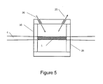
- Figure 5 is a detailed view of the measurement cell of one embodiment of the improved PALS system.
- Figure 6 illustrates an alternate implementation of the inventive MP-PALS setup shown in Fig. 4 in which two photo detector arrays are employed.
- Figure 7 displays the measured optical phase due to (a) particle diffusion alone, (b) Electrophoresis and diffusion, and (c) electrophoresis and diffusion averaged over multiple cycles of the applied electric field demonstrating that the electrophoretic component dominates, while the diffusional component is negligible.
- the sample is 1.0 mg/ml bovine serum albumin in 10 mM NaCl, 1 mM phosphate buffer titrated with phosphoric acid to pH 3.4.
- the measured mobility is + 2.26 ⁇ m.cm/V.sec, in good agreement with the value measured by capillary electrophoresis as reported by Menon and Zydney in "Measurement of Protein Charge and Ion Binding Using Capillary Electrophoresis," (Anal. Chem., V 70, pp 1581-1584 (1998 )).
- Electrophoresis is the migration of macro-ions under the influence of an electric field.
- V e the steady-state electrophoretic velocity
- V e the steady-state electrophoretic velocity
- E the applied electric field
- ⁇ the electrophoretic mobility
- ⁇ the electrophoretic mobility
- r h the macro ion's hydrodynamic radius.
- a molecule of bovine serum albumin, BSA, in an aqueous solution has m / ⁇ approximately 0.2 nsec.
- BSA bovine serum albumin
- microelectrophoresis is microelectrophoresis based on the direct observation of the electrophoretic motion of individual particles with suitable magnifying optics. This was described by A. V. Delgado et. al. in their paper “Measurement and Interpretation of Electrokinetic Phenomena” in J. Colloid Interface Sci., 309, 203 (2007 ). Nevertheless, the technique is limited by its optical resolution and cannot measure mobilities of particles much smaller than 100 nm in radius. Another disadvantage is that only a limited number of particles are measured, so the technique suffers from poor statistical accuracy. In addition, there is a selection bias based on how the particles are identified and tracked. The measurements usually take minutes or even hours to complete. As a result, joule heating, sample degradation, and electro-osmosis can present serious challenges.
- Figure 1 shows a light scattering phase diagram where the incident light is scattered by particles within the scattering volume 1 into a new direction with scattering angle ⁇ s .
- the movement of particles can be collective (due to fluid flow, electrophoresis etc.) and diffusional (due to Brownian motion).
- the diffusional component being stochastic in nature, averages to zero over time and the collective component can be revealed if enough measurement information is available to average out the diffusional component to zero. If one measures the average optical phase shift per unit time / dt due to the applied electric field, the electrophoretic mobility ⁇ may be determined.
- Figure 2 illustrates how the optical phase associated with particle diffusion averages out to zero given enough measurement time.
- Figure 2(a) shows the measured optical phase due to particle diffusion alone. A phase measurement is acquired every 2 milliseconds and normalized to sin ⁇ s .
- the sample is the electrophoretic mobility standard reference material, SRM 1980, certified by the National Institute of Standards & Technology (NIST). It consists of acicular particles with an average dimension of 60 nm x 20 nm as determined from electron microscopy. As is seen, this diffusional component is indeed random, and the corresponding phase wandering due to particle diffusion averages out to zero on the order of a few seconds.
- FIG. 2(b) graphs the measured optical phase when a 10Hz, square-wave electric field with a magnitude of 18 V/cm is applied to drive the electrophoresis.
- the scaled and offset electric field is plotted below the optical phase for visual reference.
- the optical phase consists of both an electrophoretic and a diffusional component.
- the Electrophoretic component reverses its direction whenever the electric field switches polarity, while the diffusional component remains independent of the electric field and proceeds randomly.
- the optical phase change per unit electric field is averaged over multiple cycles of the electric field and then fitted to a line for both the positive and negative sections of the electric field. Since the diffusional component averages out within several seconds, the electrophoretic mobility is readily obtained from the slopes of the fitted lines.
- the mobility of SRM 1980 is calculated to be +2.57 ⁇ m.cm/V.sec, well within the uncertainty of the NIST certified value, 2.53 ⁇ 0.12 um.cm/V.sec. The mobility is accurately determined in less than three seconds. This measurement was performed with a laser operating at 660 nm, but any wavelength may be used.
- DLS measurements may be made in two different manners: homodyne and heterodyne.
- heterodyne and heterodyne are often used inconsistently in the literature. For the purposes of this disclosure, we define them as follows: i) the homodyne mode wherein only light scattered from particles themselves is mixed, and ii) the heterodyne mode, where light scattered from the particles is mixed with some unscattered light often referred to as the local oscillator.
- V c t is the phase component due to the collective velocity v c , which is common to all particles; note that xj D ( 0 ) represents the initial position of the j th particle.
- P LO 0 and we end up with i
- signals obtained from heterodyne DLS contain the terms cos[ ⁇ jD (t)+ ⁇ c (t) ] and carry phase information of both collective and diffusional components. Therefore, in order to measure electrophoresis with light scattering, optical heterodyning is necessary as described by B. J. Beme and R. Pecora in Dynamic Light Scattering with Applications to Chemistry, Biology and Physics (John Wiley & Sons Inc. 79 [1976 ]). R. Ware and W. H. Flygare in J. Colloid Inferface Sci. 39, 670 (1972 ), showed how DLS in the heterodyne mode was used to measure the mobility of bovine serum albumin molecules at 50mg/ml in 4 mM NaCl solution.
- LDE laser Doppler electrophoresis
- LDE has important advantages over the earlier techniques. It greatly reduces the volume of sample required for mobility measurement, to milliliters or less, because the fringe pattern can be generated within the space between electrodes that are only 1-2 mm apart. Since the electric field is the voltage difference between the electrodes divided by their spacing, the reduced electrode spacing decreases the magnitude of the voltage that must be applied to generate observable electrophoresis. In addition, a large number of macro-ions contribute to the detected signal and this produces statistically sound measurements. To avoid electrode polarization, whereby ions accumulate near the electrodes and shield the bulk from the applied field, an oscillating a. c. electric filed is preferable to a d. c. field.
- the frequency of the field reversal should be made much lower than the Doppler frequency and much higher than the reciprocal of the time it takes for electro-osmosis to develop.
- the characteristic time of the development of electro-osmosis is d 2 lv, where d is the relevant linear dimension and v is the kinematic viscosity of the solution.
- v 1.0 mm 2 /sec and the time it takes for electro-osmosis to develop is about 1 sec for a 1-mm electrode gap.
- LDE cannot satisfy both conditions without applying excessively high voltages and running into problems such as profuse electrolysis and fluid convection.
- Another limitation of LDE is that both positive and negative electric fields produce the same optical signal, so the sign of the mobility cannot be determined.
- phase analysis light scattering was developed in the late 1980's by J. F. Miller, K. Shutzel, and B. Vincent in their paper "The Determination of Very Small Electrophoretic Mobilities in Polar and Nonpolar Colloidal Dispersions Using Phase Analysis Light Scattering," (J. Colloid Interface Sci. 143, 532-554 [1991 ]).
- PALS is derived from LDE and the major distinction between the techniques is that in PALS a sweeping, instead of stationary, fringe pattern is established in the scattering volume. Such fringe patterns can be generated by phase-modulating one or both of the interfering laser beams.
- the adoption of a phase demodulation scheme and band pass filtering of the detected optical signal goes a long way towards electronic noise rejection.
- a sweeping fringe pattern not only obviates the necessity of macro-ions having to traverse a few light and dark fringes during a single electric field period but also enables the determination of the sign of mobility.
- Zero-mobility, and therefore stationary, particles give rise to a Doppler frequency equivalent to that of the sweeping fringes and macro-ions migrating in the same or opposite direction of the sweeping fringes produce a Doppler frequency lower or higher than that of the sweeping fringes.
- the second laser beam instead of interfering the two leaser beams at the scattering volume, the second laser beam, the local oscillator, is mixed/heterodyned directly on the detectors with scattered light from the macro-ions and acts both as an optical amplifier and as a phase reference which is indispensable in measuring the electrophoretic velocity.
- the local oscillator is phase-modulated for the same reason as explained above.
- PALS is actually an interferometric method in which one arm is the modulated local oscillator and the other is the scattered light. As the incident laser beam goes straight through the sample, the sample volume can be further reduced.
- Another advantage of this configuration is that it allows simultaneous heterodyne and homodyne measurements since the homodyne signal can be measured before the scattered light is mixed with the local oscillator and the heterodyne is measured after the mixing.
- the responsivity may be expressed as ⁇ e e / hv , where ⁇ e , is the detector quantum efficiency ( ⁇ 70% for both silicon photodiodes and APDs at wavelengths around 700nm), h is Planck's constant, and v is the light frequency.
- the last term in the denominator represents the Johnson noise which comes from resistive components associated with the detection process, for example, the resistor R F in the feedback loop of a transimpedance amplifier as shown in Fig. 3 .
- a band pass filter following the amplifier restricts the system bandwidth ⁇ B to minimize the noise terms.
- the center of the passband ⁇ p is set equal to the modulation frequency ⁇ of the local oscillator for optimal performance.
- PALS Compared with LDE, PALS requires less time to perform a measurement and has greater sensitivity. PALS is also more suitable for measuring samples in non-polar solvents and low-mobility species, such as macro-ions close to their isoelectric points. A number of instruments currently on the market implement the PALS technique to measure the mobilities of macromolecules. Quantum-sensitive detectors such as PMTs and APDs are employed and mobility of macro-ions of size down to about 5 nm may be measured under exceptional conditions. The minimum measurable size of the macro-ions also depends on several other parameters such as the macro-ion molar mass, concentration, and the duration of the measurement. This makes PALS suitable for measuring larger particles, but not for biomolecules such as proteins, as most of these molecules are smaller than 5 nm. One of the objectives of the present invention is to overcome this size limitation, allowing the precise measurement of particles much smaller than those measureable by the methods previously discussed.
- APDs have a limited dynamic range and become nonlinear at count rates > 2 MHz, the intensity ratio between the local oscillator and the scattered light needs constant adjusting to maintain optimum sensitivity. If the ratio is too low, homodyne signal creeps into the measurement. If the ratio is too high, the APDs are driven into their nonlinear regime or saturated. Moreover, APDs are at least an order of magnitude more expensive than silicon PIN photodiodes and the associated commercial instruments are limited to a single detector channel, utilizing only a tiny fraction of the scattered light for mobility measurement.
- Protein mobility is a critically important indicator of stability: in general, the higher the mobility, the more superficially charged the proteins are, and electrostatic repulsion reduces the tendency to aggregate.
- the most interesting and most investigated proteins are those with molar masses less than ⁇ 200kD and radii often far smaller than 5nm.
- IgG molecules have a molar mass of ⁇ 150kD and a hydrodynamic radius of ⁇ 4.6nm. Measuring the mobilities of these molecules is a daunting task with any of the instruments available at the time of this invention; the proteins near the electrodes are damaged before a consistent measurement is obtained.
- the relevant signal-to-noise ratio SNR D due to particle diffusion may be expressed as SNR D ⁇ ⁇ E ( T / D ) 0.5 , where T is the total I measurement time and D is the particle translational diffusion coefficient.
- the inventive implementation of the MP-PALS technique disclosed herein solves this dilemma by performing multiple simultaneous measurements with an array of detectors.
- a diffraction/speckle pattern is produced which depends, among other things, on the extent of the scattering volume; i.e., the intensity maxima and minima depend on the dimensions of the scattering volume.
- the coherence area On any given point P on the screen, one could define a region near the point P such that the signals at all points within this region are partially coherent with that at P. This region is called the coherence area.
- N channels will reduce the measurement time by a factor of N.
- the active area of each detector element is greater than or equal to the coherence area of the scattered light, the signals collected from different detector elements are truly independent.
- Figure 7(a) shows the phase accumulation due only to diffusion. Compared to the large particle shown in Figure 2(a) , the phase wander due to diffusion is much larger.
- Figure 7(b) shows the phase accumulation with the oscillating electric field applied. For small particles the motion is masked by diffusion, and the data shown in Fig. 7(a) and 7(b) look essentially the same.
- the massive parallelism ofMP-PALS shown in Fig. 7(c) allows accurate measurement of the mobility of this small molecule. Such a measurement has not been possible prior to the invention of MP-PALS. This represents an improvement in sensitivity of at least an order of magnitude over existing PALS instruments.
- Figure 4 shows the inventive implementation of a PALS-based instrument that measures electrophoretic mobilities.
- a beamsplitter 2 splits a laser beam 3 into two beams: the sample beam 4 is focused by a lens 5 at the center of the sample cell 6 while the reference beam 7 is directed towards a prism 8 .
- the sample cell 6 is comprised of a chamber containing two electrodes 9 and sealed by the entrance window 10 and exit window 26 that permit the passage therethrough of the sample beam 4.
- the chamber is usually filled completely with sample solution.
- the absence of free surfaces deters the development of fluid convection and extends the range of sample ionic strength that may be used. For samples with higher ionic strengths, more current is expected to flow across the fluid-filled space between the electrodes, and fluid convection due to joule heating can eventually develop. Effects due to steady-state fluid convection can be accounted for in data analysis because the electrophoretic movement reverses direction whenever the applied field reverses polarity while the convective component is independent of the field polarity.
- the problem is that if the cell is not temperature-regulated the heat released within the cell causes the convection to build up over time, and it fails to reach a steady state during the measurement. Varying fluid viscosity due to a changing temperature can also complicate mobility measurements.
- One embodiment of the present invention mitigates this problem by cooling the bottom of the cell and heating the top to develop an antagonistic temperature gradient and stabilizing the system against convection.
- the built-in electrodes 9 serve three purposes: the regulation of cell/sample temperature, the measurement of sample conductivity ⁇ , and the application of an electric field E to drive electrophoresis.
- the body of the cell must be electrically insulating and common electrical insulators (such as plastic) are typically thermal insulators as well and, therefore, are not suitable for temperature regulating the cell. Accordingly, the thermally conductive electrodes must be temperature regulated. This may be achieved by attaching thereon thermoelectric devices to heat or cool the contained sample as well as stabilize the cell/sample temperature while electric power is being dissipated in conducting samples.
- the conductivity ⁇ of the solution of interest is determined by applying a voltage pulse of known magnitude between the electrodes and measuring the resulting current, which is then compared with that of a conductivity standard such as, for example, potassium chloride, KC1.
- a conductivity standard such as, for example, potassium chloride, KC1.
- the electrodes may be made of or coated with various conducting materials such as stainless steel, gold, platinum or palladium.
- the material of choice may be selected on the basis of its tarnish resistance and chemical compatibility with the sample of interest.
- the dissipated power per unit volume is E ⁇ J, or ⁇ lEl 2 .
- a correspondingly high current is needed to generate a commensurate electric field. Therefore, the joule heating goes linearly with the sample conductivity.
- a constant electric field 20 V/cm in a 10 ms/cm sample entails joule heating of the order of 1°C/sec in aqueous solutions.
- ⁇ increases, the measurement grows more vulnerable to fluid convection and a changing viscosity due to a rising temperature.
- high currents may produce various deleterious effects on the electrodes as well as the molecules being measured.
- the focused sample beam traverses the sample cell 6, a portion of the light is scattered from the particles undergoing electrophoresis. That fraction of the scattered light 12 that can leave the sample cell through exit window 10 along with the unscattered sample beam 17 are then collimated by condenser lens 11 to form a combined collimated sample beam whose unscattered component 17 may be attenuated by attenuator means 18 before combining with the collected scattered fraction to reflect from mirror means 13 . These reflected components are then further reflected from beamsplitter means 14 to fall upon an array of detectors 15. The mirror 13 and beamsplitter 14 achieve co linearity between the collimated scattered sample beam with its unscattered component and the reference beam 16 for optimal optical mixing/heterodyning at the detector array 15.
- Each array element intercepts a solid angle of scattered light and a range of corresponding scattering vectors, which are determined by the focal length of the condenser lens 11 as well as the positions and dimensions of the array elements.
- the unscattered portion of the now collimated sample beam 17 has been attenuated as may be required before reflecting a portion thereof at the beamsplitter 14 to be incident upon a particular array element 19 that will serve as the sample beam monitor.
- the internal region of the sample cell 6 is accessible to fluid flow through an inlet port 20 and an outlet port 21 as shown in Fig. 5 , thus allowing the sample contained therein to be changed without the need to remove the cell.
- the portion of the laser beam reflected from the beamsplitter 2 is retro-reflected successively by a right-angle prism 8. Since that prism 8 is used as a retroreflector, its hypotenuse surface is anti-reflection coated to maximize light transmission.
- the prism 8 is continuously driven by a piezo-electric actuator 22 that imparts phase modulation parallel to the beam to facilitate the determination of the sign of measured electrophoretic mobilities and the rejection of electronic noise.
- the prism 8 serves two additional purposes:
- the beam is redirected by a mirror 23 and then shaped by appropriate optics to serve as the reference beam 16, which is then transmitted through the beamsplitter 14 and falls onto the detector array 15, where it recombines collinearly with the reflected scattered sample beam fraction 12.
- FIG. 4 the reference beam transmitted through beam splitter 14 and the sample beam reflected by beam splitter 14 are measured by detector array 15.
- An alternative embodiment, shown in Fig. 6 includes a second photo detector array 15' which collects the reference beam reflected by beam splitter 14 and the sample beam transmitted by beam splitter 14. Detector arrays in positions 15 and 15' may be used simultaneously for improved averaging.
- a two-dimensional array of detectors may be substituted for the linear array 15 for detection, and the shape of the reference beam 16 would be adjusted to illuminate effectively the array of photo detectors 15.
- a Galilean telescope (with a proper magnification) could be used in reverse to obtain, thereby, a disk-shaped reference beam which then mixes with the also disk-shaped sample beam scattered fraction.
- a linear detector array 15 is used and the beam shaping is accomplished with a pair of cylindrical lenses 24 and 25 to obtain an elongated reference beam 16.
- an elongated reference beam makes the most economical use of available optical power.
- the collimated sample scattered fraction and reference beams must be both temporally and spatially coherent so that the interferometric-based measurement of mobility may be fully realized.
- the achieved coherence in both time and space are discussed below.
- the coherence length of the light source should be much longer than the path length difference between the sample and reference beams; this is easily achieved by various coherent light sources, for example, gas lasers, solid-state lasers and frequency-stabilized semiconductor lasers.
- coherent light sources for example, gas lasers, solid-state lasers and frequency-stabilized semiconductor lasers.
- the selection of a specific coherent light source is dictated by the sample to which it is applied, e.g. for samples exhibiting absorption and/or fluorescence, and cost considerations, among other factors.
- free space optics combined with silicon photodiode arrays are used for detection; the coherence in space (or wavefront phase-matching) is achieved by proper placement and orientation of the mirror 13 and the beamsplitter 14 to ensure collinear propagation of the collimated sample and reference beams.
- the maximum allowed angular deviation between the two beams ⁇ D is equal to ⁇ / 2mv where w is the array element dimension and ⁇ is the wavelength of the light in vacuum. This requires careful alignment of the optical system.
- All PALS instruments available on the market today attain spatial coherence differently. They use optical fibers for light collection. Such fibers transmit light in discrete "modes".
- a shortened measurement time reduces the duration the sample molecules must be subjected to the electric current, helping to preserve thereby the integrity of samples as well as the system electrodes. This is especially important for precious and fragile samples of which proteins are an exemplar class.
- photodiode arrays possess excellent linearity and a huge dynamic range (up to a factor of 10 11 ).
- Taking advantage of the enormous dynamic range one may use a very high intensity ratio of local oscillator to scattered light compared with systems that use APDs. This eliminates the need to adjust the intensity ratio between the two beams and makes shot-noise-limited performance possible.
- modulating the phase of the local oscillator/reference beam one may detect the signal with the modulating frequency chosen from an almost limitless variety of possibilities. This transforms the measurement of interest away from one that is DC-based and allows the use of analog coupling. In this manner, the noise bandwidth is greatly reduced by band pass filtering the signal about the modulation frequency. Moving away from DC also helps reduce the 1 lf noise that is inherent in analog detectors.
- APDs are more expensive than entire photodiode arrays by more than an order of magnitude.
- Information throughput per unit cost in the inventive modification of PALS exceeds significantly that of systems/instruments utilizing light fibers and APDs or PMTs.
Landscapes
- Chemical & Material Sciences (AREA)
- Health & Medical Sciences (AREA)
- Chemical Kinetics & Catalysis (AREA)
- Life Sciences & Earth Sciences (AREA)
- Organic Chemistry (AREA)
- Polymers & Plastics (AREA)
- Medicinal Chemistry (AREA)
- Molecular Biology (AREA)
- Biochemistry (AREA)
- General Health & Medical Sciences (AREA)
- General Physics & Mathematics (AREA)
- Immunology (AREA)
- Pathology (AREA)
- Analytical Chemistry (AREA)
- Physics & Mathematics (AREA)
- Electrochemistry (AREA)
- Investigating Or Analysing Materials By Optical Means (AREA)
- Electrochromic Elements, Electrophoresis, Or Variable Reflection Or Absorption Elements (AREA)
Applications Claiming Priority (2)
| Application Number | Priority Date | Filing Date | Title |
|---|---|---|---|
| US30878110P | 2010-02-26 | 2010-02-26 | |
| US12/782,682 US8441638B2 (en) | 2010-02-26 | 2010-05-18 | Apparatus to measure particle mobility in solution with scattered and unscattered light |
Publications (2)
| Publication Number | Publication Date |
|---|---|
| EP2365327A1 true EP2365327A1 (fr) | 2011-09-14 |
| EP2365327B1 EP2365327B1 (fr) | 2015-09-02 |
Family
ID=43947337
Family Applications (1)
| Application Number | Title | Priority Date | Filing Date |
|---|---|---|---|
| EP10197163.8A Active EP2365327B1 (fr) | 2010-02-26 | 2010-12-28 | Procédé et appareil permettant de mesurer la mobilité des particules dans une solution |
Country Status (4)
| Country | Link |
|---|---|
| US (2) | US8441638B2 (fr) |
| EP (1) | EP2365327B1 (fr) |
| JP (1) | JP5788186B2 (fr) |
| CN (1) | CN102192867B (fr) |
Cited By (1)
| Publication number | Priority date | Publication date | Assignee | Title |
|---|---|---|---|---|
| EP2780691A4 (fr) * | 2011-11-16 | 2015-07-01 | Luna Innovations Inc | Procédé et appareil d'électrophorèse de type ofdr |
Families Citing this family (26)
| Publication number | Priority date | Publication date | Assignee | Title |
|---|---|---|---|---|
| US8702942B2 (en) * | 2010-12-17 | 2014-04-22 | Malvern Instruments, Ltd. | Laser doppler electrophoresis using a diffusion barrier |
| US10648945B2 (en) | 2010-12-17 | 2020-05-12 | Malvern Panalytical Limited | Laser doppler electrophoresis using a diffusion barrier |
| JP5805989B2 (ja) * | 2011-04-26 | 2015-11-10 | 大塚電子株式会社 | 電気泳動移動度測定用セル並びにそれを用いた測定装置及び測定方法 |
| WO2012172330A1 (fr) | 2011-06-15 | 2012-12-20 | Malvern Instruments Limited | Mesure de la charge de surface |
| US8964177B2 (en) | 2012-04-27 | 2015-02-24 | Wyatt Technology Corporation | Method and apparatus to illuminate sample and containing vessel in a light scattering detector |
| EP2735870B1 (fr) | 2012-11-27 | 2015-02-25 | Anton Paar GmbH | Surveillance de modulateur durant la mesure de l'électromobilité |
| US20140209466A1 (en) | 2013-01-31 | 2014-07-31 | Wyatt Technology Corporation | Corrosion resistant electrodes for electrophoretic mobility measurements and method for their fabrication |
| EP3017291A4 (fr) * | 2013-07-03 | 2017-01-25 | Wyatt Technology Corporation | Procédé et appareil pour contrôler un report d'échantillon dans des instruments d'analyse |
| KR101492343B1 (ko) | 2013-11-15 | 2015-02-11 | 한국과학기술원 | 광 산란 패턴 검출 장치 및 광 산란 패턴 검출 방법 |
| WO2016073830A1 (fr) * | 2014-11-06 | 2016-05-12 | Wyatt Technology Corporation | Procédé et appareil de mesure de mobilité électrophorétique d'échantillon fluide |
| WO2017031466A1 (fr) * | 2015-08-19 | 2017-02-23 | Spectra Systems Corporation | Mélange de deux ondes non dégénérées pour identification et séparation de macromolécules |
| US10379114B2 (en) | 2015-08-19 | 2019-08-13 | Solaris Nanosciences, Inc. | Nondegenerate two-wave mixing for identifying and separating macromolecules |
| CN105203831B (zh) * | 2015-09-30 | 2018-02-02 | 丹东百特仪器有限公司 | 光学法颗粒Zeta电位测量时电位极性测量方法及装置 |
| CN108291842B (zh) | 2015-11-18 | 2020-09-18 | 基础科学研究院 | 光波的波形测量装置和方法 |
| GB201609017D0 (en) * | 2016-05-23 | 2016-07-06 | Isis Innovation | Characterisation of particles |
| JP6681302B2 (ja) * | 2016-09-01 | 2020-04-15 | 株式会社日立製作所 | 放射線モニタ、及び放射線モニタの解析方法 |
| WO2018071418A1 (fr) * | 2016-10-10 | 2018-04-19 | Spectra Systems Corporation | Mélange à deux ondes non dégénéré pour identifier et séparer des macromolécules |
| US10330638B2 (en) | 2017-01-16 | 2019-06-25 | Wyatt Technology Corporation | Method and apparatus to characterize pressurized liquid sample |
| WO2018175039A1 (fr) * | 2017-03-20 | 2018-09-27 | Miller John F | Mesure de mobilité électrophorétique |
| CN109505592B (zh) * | 2017-09-14 | 2021-10-12 | 中国石油化工股份有限公司 | 高增益随钻电阻率信号接收装置 |
| RU2722066C2 (ru) * | 2018-11-19 | 2020-05-26 | Самсунг Электроникс Ко., Лтд. | Многоканальный датчик пыли |
| US11841311B2 (en) | 2018-11-19 | 2023-12-12 | Samsung Electronics Co., Ltd. | Multimodal dust sensor |
| EP4191344B1 (fr) * | 2021-12-06 | 2026-01-28 | Imec VZW | Dispositif d'imagerie et procédé d'imagerie holographique d'échantillons |
| JP7813177B2 (ja) * | 2022-04-13 | 2026-02-12 | 大塚電子株式会社 | ゼータ電位測定用治具セット |
| US11953412B2 (en) * | 2022-06-16 | 2024-04-09 | Robert Dickerman | Quadrature phase analysis light scattering for electrophoresis and zeta potential measurements |
| CN116380726B (zh) * | 2022-12-16 | 2025-07-01 | 暨南大学 | 一种确定纳米塑料迁移参数随pH连续变化的方法 |
Citations (4)
| Publication number | Priority date | Publication date | Assignee | Title |
|---|---|---|---|---|
| US4097153A (en) * | 1976-05-17 | 1978-06-27 | Sentrol Systems Ltd. | Method and apparatus for measuring the electrophoretic mobility of suspended particles |
| WO1985004486A1 (fr) * | 1984-03-23 | 1985-10-10 | Coulter Electronics Of New England, Inc. | Appareil et procede de diffusion de lumiere electrophoretique |
| EP0916938A2 (fr) | 1997-11-13 | 1999-05-19 | Biophotonics Information Laboratories Ltd. | Appareil de mesure optique |
| US20060114467A1 (en) * | 2004-12-01 | 2006-06-01 | Particle Sizing Systems, Inc. | Methods and apparatus for electrophoretic mobility determination using phase light scattering analysis |
Family Cites Families (11)
| Publication number | Priority date | Publication date | Assignee | Title |
|---|---|---|---|---|
| US3532427A (en) * | 1969-04-22 | 1970-10-06 | T O Paine | Laser doppler system for measuring three dimensional vector velocity |
| US3732014A (en) * | 1972-01-31 | 1973-05-08 | Gen Electric | Electromagnetic radiation apparatus for analyzing small particles |
| GB1377831A (en) * | 1972-04-17 | 1974-12-18 | Secr Defence | Interferometers for fluid flow measurements |
| US5171534A (en) * | 1984-01-16 | 1992-12-15 | California Institute Of Technology | Automated DNA sequencing technique |
| JPH01253633A (ja) * | 1988-04-01 | 1989-10-09 | Hitachi Ltd | 吸光光度検出器 |
| US5215883A (en) * | 1990-07-09 | 1993-06-01 | The Research Foundation | Electrophoretic mobility of fluorophore labeled particles in gels by fluorophore movement after photobleaching |
| US5600444A (en) * | 1994-01-13 | 1997-02-04 | San Diego State University Foundation | Detecting analyte light absorption utilizing degenerate four wave mixing |
| JPH08233736A (ja) * | 1995-02-27 | 1996-09-13 | Nohmi Bosai Ltd | 微粒子検出センサ |
| JP3076016B2 (ja) * | 1997-11-13 | 2000-08-14 | 株式会社生体光情報研究所 | 光計測装置 |
| JP4334899B2 (ja) * | 2003-02-25 | 2009-09-30 | 大塚電子株式会社 | 電気泳動速度測定装置 |
| GB2429058B (en) * | 2004-03-06 | 2008-12-03 | Michael Trainer | Method and apparatus for determining the size and shape of particles |
-
2010
- 2010-05-18 US US12/782,682 patent/US8441638B2/en active Active
- 2010-12-28 EP EP10197163.8A patent/EP2365327B1/fr active Active
-
2011
- 2011-02-03 JP JP2011021731A patent/JP5788186B2/ja not_active Expired - Fee Related
- 2011-02-25 CN CN201110050936.1A patent/CN102192867B/zh not_active Expired - Fee Related
-
2013
- 2013-03-01 US US13/783,160 patent/US8525991B2/en active Active
Patent Citations (4)
| Publication number | Priority date | Publication date | Assignee | Title |
|---|---|---|---|---|
| US4097153A (en) * | 1976-05-17 | 1978-06-27 | Sentrol Systems Ltd. | Method and apparatus for measuring the electrophoretic mobility of suspended particles |
| WO1985004486A1 (fr) * | 1984-03-23 | 1985-10-10 | Coulter Electronics Of New England, Inc. | Appareil et procede de diffusion de lumiere electrophoretique |
| EP0916938A2 (fr) | 1997-11-13 | 1999-05-19 | Biophotonics Information Laboratories Ltd. | Appareil de mesure optique |
| US20060114467A1 (en) * | 2004-12-01 | 2006-06-01 | Particle Sizing Systems, Inc. | Methods and apparatus for electrophoretic mobility determination using phase light scattering analysis |
Non-Patent Citations (13)
| Title |
|---|
| A. V. DELGADO: "Measurement and Interpretation of Electrokinetic Phenomena", J. COLLOID INTERFACE SCI., vol. 309, 2007, pages 203 |
| A. YARIV: "Optical Electronics in Modern Communications", 1997, OXFORD UNIVERSITY PRESS, pages: 423 |
| B. J. BERNE; R. PECORA: "Dynamic Light Scattering with Applications to Chemistry, Biology and Physics", vol. 79, 1976, JOHN WILEY & SONS INC. |
| C. J. OLIVER: "Photon Correlation and Light Beating Spectroscopy", 1974, PLENUM, article "Correlation techniques", pages: 151 - 223 |
| E. E. UZGIRIS, PROG. SURF SCI., vol. 10, 1981, pages 53 |
| J. F. MILLER; K. SCHATZEL; B. VINCENT: "The Determination of Very Small Electrophoretic Mobilities in Polar and Nonpolar Colloidal Dispersions Using Phase Analysis Light Scattering", J. COLLOID INTERFACE SCI., vol. 143, 1991, pages 532 - 554 |
| J. F. MILLERK. SCHATZELB. VINCENT: "The Determination of Very Small Electrophoretic Mobilities in Polar and Nonpolar Colloidal Dispersions Using Phase Analysis Light Scattering", J. COLLOID INTERFACE SCI., vol. 143, 19 July 2007 (2007-07-19), pages 532 - 554, XP024208824 * |
| MENON; ZYDNEY: "Measurement of Protein Charge and Ion Binding Using Capillary Electrophoresis", ANAL. CHEM., vol. 70, 1998, pages 1581 - 1584 |
| MILLER J. ET AL: "The Determination of Very Small Electrophoretic Mobilities in Polar and NonpolarColloidal Dispersions Using Phase Analysis Light Scattering", OURNAL OF COLLOID AND INTERFACE SCIENCE, vol. 143, no. 2, 1 May 1991 (1991-05-01), pages 532 - 554, XP002636988 |
| R. A. ALBERTY: "An Introduction to Electrophoresis", J. CLEM. EDUC., vol. 25, 1948, pages 426,619 |
| R. WARE; W. H. FLYGARE, J. COLLOID INFERFACE SCI., vol. 39, 1972, pages 670 |
| ROBERT G. W. BROWN: "Homodyne Optical Fiber Dynamic Light Scattering", APPL. OPT., vol. 40, 2001, pages 4004 - 4010 |
| V. P. DOLE, J. AM. CHEM. SOC., vol. 67, 1945, pages 1119 |
Cited By (2)
| Publication number | Priority date | Publication date | Assignee | Title |
|---|---|---|---|---|
| EP2780691A4 (fr) * | 2011-11-16 | 2015-07-01 | Luna Innovations Inc | Procédé et appareil d'électrophorèse de type ofdr |
| US9244011B2 (en) | 2011-11-16 | 2016-01-26 | Luna Innovations Incorporated | Method and apparatus for OFDR-based electrophoresis |
Also Published As
| Publication number | Publication date |
|---|---|
| US8441638B2 (en) | 2013-05-14 |
| US20130182254A1 (en) | 2013-07-18 |
| CN102192867A (zh) | 2011-09-21 |
| JP2011180584A (ja) | 2011-09-15 |
| JP5788186B2 (ja) | 2015-09-30 |
| CN102192867B (zh) | 2016-08-03 |
| EP2365327B1 (fr) | 2015-09-02 |
| US8525991B2 (en) | 2013-09-03 |
| US20110210002A1 (en) | 2011-09-01 |
Similar Documents
| Publication | Publication Date | Title |
|---|---|---|
| EP2365327B1 (fr) | Procédé et appareil permettant de mesurer la mobilité des particules dans une solution | |
| US12607599B2 (en) | Method and apparatus for detecting particles, like biological macromolecules or nanoparticles | |
| CN110402380B (zh) | 利用可调焦透镜的粒子表征 | |
| US11079420B2 (en) | Surface charge measurement | |
| Gardel et al. | Microrheology | |
| US9341564B2 (en) | Apparatus for high-throughput suspension measurements | |
| JPH0531935B2 (fr) | ||
| Smith et al. | Apparatus and methods for laser Doppler electrophoresis | |
| US9360416B2 (en) | Twin-focus photothermal correlation spectroscopy method and device for the characterization of dynamical processes in liquids and biomaterials with the help of absorbing markers | |
| CN115508421B (zh) | 通过余弦拟合技术测量Zeta电位的方法及装置 | |
| CN113884558A (zh) | 一种基于相位分析光散射技术和毛细管电极检测装置的准确检测悬浮体系Zeta电位的检测方法 | |
| US20250110035A1 (en) | Apparatus to measure electrophoretic mobility | |
| Knowles et al. | Measurement of the dynamic structure function of fluorescently labeled complex fluids by Fourier imaging correlation spectroscopy | |
| RU2416803C2 (ru) | Лазерный доплеровский анализатор | |
| Grassman et al. | Structure and dynamics of fluorescently labeled complex fluids by Fourier imaging correlation spectroscopy | |
| Suparno et al. | In Depth Review on Light Scattering Techniques for Characterization of Protein | |
| US20240377355A1 (en) | Apparatus to measure electrophoretic mobility | |
| BR102024004312A2 (pt) | Espectrômetro de correlação de fótons portátil e processo para determinação de parâmetros cinéticos da ligação entre os nanossensores e analitos | |
| Lavania et al. | Sizing single trapped nanoparticles with interferometric scattering fluctuations | |
| SU1109621A1 (ru) | Способ измерени электрофоретической подвижности частиц суспензий | |
| Beunis et al. | Fast and precise measurements of particle charge with optical trapping electrophoresis | |
| Speets | Measuring Size and Electrophoretic Mobility of Sub 100 nm Particles by Single Particle Tracking | |
| Macfadyen et al. | Photon correlation spectroscopy and electrophoretic light scattering using optical fibers |
Legal Events
| Date | Code | Title | Description |
|---|---|---|---|
| PUAI | Public reference made under article 153(3) epc to a published international application that has entered the european phase |
Free format text: ORIGINAL CODE: 0009012 |
|
| AK | Designated contracting states |
Kind code of ref document: A1 Designated state(s): AL AT BE BG CH CY CZ DE DK EE ES FI FR GB GR HR HU IE IS IT LI LT LU LV MC MK MT NL NO PL PT RO RS SE SI SK SM TR |
|
| AX | Request for extension of the european patent |
Extension state: BA ME |
|
| 17P | Request for examination filed |
Effective date: 20120314 |
|
| 17Q | First examination report despatched |
Effective date: 20120912 |
|
| TPAC | Observations filed by third parties |
Free format text: ORIGINAL CODE: EPIDOSNTIPA |
|
| GRAP | Despatch of communication of intention to grant a patent |
Free format text: ORIGINAL CODE: EPIDOSNIGR1 |
|
| INTG | Intention to grant announced |
Effective date: 20150311 |
|
| GRAS | Grant fee paid |
Free format text: ORIGINAL CODE: EPIDOSNIGR3 |
|
| GRAA | (expected) grant |
Free format text: ORIGINAL CODE: 0009210 |
|
| AK | Designated contracting states |
Kind code of ref document: B1 Designated state(s): AL AT BE BG CH CY CZ DE DK EE ES FI FR GB GR HR HU IE IS IT LI LT LU LV MC MK MT NL NO PL PT RO RS SE SI SK SM TR |
|
| REG | Reference to a national code |
Ref country code: GB Ref legal event code: FG4D |
|
| REG | Reference to a national code |
Ref country code: AT Ref legal event code: REF Ref document number: 746938 Country of ref document: AT Kind code of ref document: T Effective date: 20150915 Ref country code: CH Ref legal event code: EP |
|
| REG | Reference to a national code |
Ref country code: IE Ref legal event code: FG4D |
|
| REG | Reference to a national code |
Ref country code: DE Ref legal event code: R096 Ref document number: 602010027135 Country of ref document: DE |
|
| REG | Reference to a national code |
Ref country code: FR Ref legal event code: PLFP Year of fee payment: 6 |
|
| REG | Reference to a national code |
Ref country code: AT Ref legal event code: MK05 Ref document number: 746938 Country of ref document: AT Kind code of ref document: T Effective date: 20150902 |
|
| PG25 | Lapsed in a contracting state [announced via postgrant information from national office to epo] |
Ref country code: GR Free format text: LAPSE BECAUSE OF FAILURE TO SUBMIT A TRANSLATION OF THE DESCRIPTION OR TO PAY THE FEE WITHIN THE PRESCRIBED TIME-LIMIT Effective date: 20151203 Ref country code: LT Free format text: LAPSE BECAUSE OF FAILURE TO SUBMIT A TRANSLATION OF THE DESCRIPTION OR TO PAY THE FEE WITHIN THE PRESCRIBED TIME-LIMIT Effective date: 20150902 Ref country code: NO Free format text: LAPSE BECAUSE OF FAILURE TO SUBMIT A TRANSLATION OF THE DESCRIPTION OR TO PAY THE FEE WITHIN THE PRESCRIBED TIME-LIMIT Effective date: 20151202 Ref country code: LV Free format text: LAPSE BECAUSE OF FAILURE TO SUBMIT A TRANSLATION OF THE DESCRIPTION OR TO PAY THE FEE WITHIN THE PRESCRIBED TIME-LIMIT Effective date: 20150902 Ref country code: FI Free format text: LAPSE BECAUSE OF FAILURE TO SUBMIT A TRANSLATION OF THE DESCRIPTION OR TO PAY THE FEE WITHIN THE PRESCRIBED TIME-LIMIT Effective date: 20150902 |
|
| REG | Reference to a national code |
Ref country code: LT Ref legal event code: MG4D Ref country code: NL Ref legal event code: MP Effective date: 20150902 |
|
| PG25 | Lapsed in a contracting state [announced via postgrant information from national office to epo] |
Ref country code: PL Free format text: LAPSE BECAUSE OF FAILURE TO SUBMIT A TRANSLATION OF THE DESCRIPTION OR TO PAY THE FEE WITHIN THE PRESCRIBED TIME-LIMIT Effective date: 20150902 Ref country code: RS Free format text: LAPSE BECAUSE OF FAILURE TO SUBMIT A TRANSLATION OF THE DESCRIPTION OR TO PAY THE FEE WITHIN THE PRESCRIBED TIME-LIMIT Effective date: 20150902 Ref country code: AT Free format text: LAPSE BECAUSE OF FAILURE TO SUBMIT A TRANSLATION OF THE DESCRIPTION OR TO PAY THE FEE WITHIN THE PRESCRIBED TIME-LIMIT Effective date: 20150902 Ref country code: SE Free format text: LAPSE BECAUSE OF FAILURE TO SUBMIT A TRANSLATION OF THE DESCRIPTION OR TO PAY THE FEE WITHIN THE PRESCRIBED TIME-LIMIT Effective date: 20150902 Ref country code: ES Free format text: LAPSE BECAUSE OF FAILURE TO SUBMIT A TRANSLATION OF THE DESCRIPTION OR TO PAY THE FEE WITHIN THE PRESCRIBED TIME-LIMIT Effective date: 20150902 |
|
| PG25 | Lapsed in a contracting state [announced via postgrant information from national office to epo] |
Ref country code: IT Free format text: LAPSE BECAUSE OF FAILURE TO SUBMIT A TRANSLATION OF THE DESCRIPTION OR TO PAY THE FEE WITHIN THE PRESCRIBED TIME-LIMIT Effective date: 20150902 Ref country code: EE Free format text: LAPSE BECAUSE OF FAILURE TO SUBMIT A TRANSLATION OF THE DESCRIPTION OR TO PAY THE FEE WITHIN THE PRESCRIBED TIME-LIMIT Effective date: 20150902 Ref country code: NL Free format text: LAPSE BECAUSE OF FAILURE TO SUBMIT A TRANSLATION OF THE DESCRIPTION OR TO PAY THE FEE WITHIN THE PRESCRIBED TIME-LIMIT Effective date: 20150902 Ref country code: IS Free format text: LAPSE BECAUSE OF FAILURE TO SUBMIT A TRANSLATION OF THE DESCRIPTION OR TO PAY THE FEE WITHIN THE PRESCRIBED TIME-LIMIT Effective date: 20160102 Ref country code: SK Free format text: LAPSE BECAUSE OF FAILURE TO SUBMIT A TRANSLATION OF THE DESCRIPTION OR TO PAY THE FEE WITHIN THE PRESCRIBED TIME-LIMIT Effective date: 20150902 Ref country code: CZ Free format text: LAPSE BECAUSE OF FAILURE TO SUBMIT A TRANSLATION OF THE DESCRIPTION OR TO PAY THE FEE WITHIN THE PRESCRIBED TIME-LIMIT Effective date: 20150902 |
|
| PG25 | Lapsed in a contracting state [announced via postgrant information from national office to epo] |
Ref country code: BE Free format text: LAPSE BECAUSE OF NON-PAYMENT OF DUE FEES Effective date: 20151231 Ref country code: RO Free format text: LAPSE BECAUSE OF FAILURE TO SUBMIT A TRANSLATION OF THE DESCRIPTION OR TO PAY THE FEE WITHIN THE PRESCRIBED TIME-LIMIT Effective date: 20150902 Ref country code: PT Free format text: LAPSE BECAUSE OF FAILURE TO SUBMIT A TRANSLATION OF THE DESCRIPTION OR TO PAY THE FEE WITHIN THE PRESCRIBED TIME-LIMIT Effective date: 20160104 |
|
| REG | Reference to a national code |
Ref country code: DE Ref legal event code: R097 Ref document number: 602010027135 Country of ref document: DE |
|
| PLBE | No opposition filed within time limit |
Free format text: ORIGINAL CODE: 0009261 |
|
| STAA | Information on the status of an ep patent application or granted ep patent |
Free format text: STATUS: NO OPPOSITION FILED WITHIN TIME LIMIT |
|
| PG25 | Lapsed in a contracting state [announced via postgrant information from national office to epo] |
Ref country code: MC Free format text: LAPSE BECAUSE OF FAILURE TO SUBMIT A TRANSLATION OF THE DESCRIPTION OR TO PAY THE FEE WITHIN THE PRESCRIBED TIME-LIMIT Effective date: 20150902 Ref country code: LU Free format text: LAPSE BECAUSE OF FAILURE TO SUBMIT A TRANSLATION OF THE DESCRIPTION OR TO PAY THE FEE WITHIN THE PRESCRIBED TIME-LIMIT Effective date: 20151228 |
|
| REG | Reference to a national code |
Ref country code: CH Ref legal event code: PL |
|
| 26N | No opposition filed |
Effective date: 20160603 |
|
| PG25 | Lapsed in a contracting state [announced via postgrant information from national office to epo] |
Ref country code: SI Free format text: LAPSE BECAUSE OF FAILURE TO SUBMIT A TRANSLATION OF THE DESCRIPTION OR TO PAY THE FEE WITHIN THE PRESCRIBED TIME-LIMIT Effective date: 20150902 Ref country code: DK Free format text: LAPSE BECAUSE OF FAILURE TO SUBMIT A TRANSLATION OF THE DESCRIPTION OR TO PAY THE FEE WITHIN THE PRESCRIBED TIME-LIMIT Effective date: 20150902 |
|
| REG | Reference to a national code |
Ref country code: IE Ref legal event code: MM4A |
|
| PG25 | Lapsed in a contracting state [announced via postgrant information from national office to epo] |
Ref country code: CH Free format text: LAPSE BECAUSE OF NON-PAYMENT OF DUE FEES Effective date: 20151231 Ref country code: LI Free format text: LAPSE BECAUSE OF NON-PAYMENT OF DUE FEES Effective date: 20151231 Ref country code: IE Free format text: LAPSE BECAUSE OF NON-PAYMENT OF DUE FEES Effective date: 20151228 |
|
| REG | Reference to a national code |
Ref country code: FR Ref legal event code: PLFP Year of fee payment: 7 |
|
| PG25 | Lapsed in a contracting state [announced via postgrant information from national office to epo] |
Ref country code: BE Free format text: LAPSE BECAUSE OF FAILURE TO SUBMIT A TRANSLATION OF THE DESCRIPTION OR TO PAY THE FEE WITHIN THE PRESCRIBED TIME-LIMIT Effective date: 20150902 |
|
| PG25 | Lapsed in a contracting state [announced via postgrant information from national office to epo] |
Ref country code: SM Free format text: LAPSE BECAUSE OF FAILURE TO SUBMIT A TRANSLATION OF THE DESCRIPTION OR TO PAY THE FEE WITHIN THE PRESCRIBED TIME-LIMIT Effective date: 20150902 Ref country code: BG Free format text: LAPSE BECAUSE OF FAILURE TO SUBMIT A TRANSLATION OF THE DESCRIPTION OR TO PAY THE FEE WITHIN THE PRESCRIBED TIME-LIMIT Effective date: 20150902 Ref country code: HU Free format text: LAPSE BECAUSE OF FAILURE TO SUBMIT A TRANSLATION OF THE DESCRIPTION OR TO PAY THE FEE WITHIN THE PRESCRIBED TIME-LIMIT; INVALID AB INITIO Effective date: 20101228 |
|
| PG25 | Lapsed in a contracting state [announced via postgrant information from national office to epo] |
Ref country code: CY Free format text: LAPSE BECAUSE OF FAILURE TO SUBMIT A TRANSLATION OF THE DESCRIPTION OR TO PAY THE FEE WITHIN THE PRESCRIBED TIME-LIMIT Effective date: 20150902 |
|
| PG25 | Lapsed in a contracting state [announced via postgrant information from national office to epo] |
Ref country code: HR Free format text: LAPSE BECAUSE OF FAILURE TO SUBMIT A TRANSLATION OF THE DESCRIPTION OR TO PAY THE FEE WITHIN THE PRESCRIBED TIME-LIMIT Effective date: 20150902 |
|
| PG25 | Lapsed in a contracting state [announced via postgrant information from national office to epo] |
Ref country code: MT Free format text: LAPSE BECAUSE OF FAILURE TO SUBMIT A TRANSLATION OF THE DESCRIPTION OR TO PAY THE FEE WITHIN THE PRESCRIBED TIME-LIMIT Effective date: 20150902 Ref country code: TR Free format text: LAPSE BECAUSE OF FAILURE TO SUBMIT A TRANSLATION OF THE DESCRIPTION OR TO PAY THE FEE WITHIN THE PRESCRIBED TIME-LIMIT Effective date: 20150902 |
|
| REG | Reference to a national code |
Ref country code: FR Ref legal event code: PLFP Year of fee payment: 8 |
|
| PGFP | Annual fee paid to national office [announced via postgrant information from national office to epo] |
Ref country code: FR Payment date: 20171219 Year of fee payment: 8 |
|
| PGFP | Annual fee paid to national office [announced via postgrant information from national office to epo] |
Ref country code: DE Payment date: 20180109 Year of fee payment: 8 |
|
| PG25 | Lapsed in a contracting state [announced via postgrant information from national office to epo] |
Ref country code: MK Free format text: LAPSE BECAUSE OF FAILURE TO SUBMIT A TRANSLATION OF THE DESCRIPTION OR TO PAY THE FEE WITHIN THE PRESCRIBED TIME-LIMIT Effective date: 20150902 |
|
| PG25 | Lapsed in a contracting state [announced via postgrant information from national office to epo] |
Ref country code: AL Free format text: LAPSE BECAUSE OF FAILURE TO SUBMIT A TRANSLATION OF THE DESCRIPTION OR TO PAY THE FEE WITHIN THE PRESCRIBED TIME-LIMIT Effective date: 20150902 |
|
| REG | Reference to a national code |
Ref country code: DE Ref legal event code: R119 Ref document number: 602010027135 Country of ref document: DE |
|
| PG25 | Lapsed in a contracting state [announced via postgrant information from national office to epo] |
Ref country code: DE Free format text: LAPSE BECAUSE OF NON-PAYMENT OF DUE FEES Effective date: 20190702 Ref country code: FR Free format text: LAPSE BECAUSE OF NON-PAYMENT OF DUE FEES Effective date: 20181231 |
|
| P01 | Opt-out of the competence of the unified patent court (upc) registered |
Effective date: 20230526 |
|
| PGFP | Annual fee paid to national office [announced via postgrant information from national office to epo] |
Ref country code: GB Payment date: 20251119 Year of fee payment: 16 |