EP2365402A2 - Entwicklungskartusche und Bilderzeugungsvorrichtung - Google Patents
Entwicklungskartusche und Bilderzeugungsvorrichtung Download PDFInfo
- Publication number
- EP2365402A2 EP2365402A2 EP20110001509 EP11001509A EP2365402A2 EP 2365402 A2 EP2365402 A2 EP 2365402A2 EP 20110001509 EP20110001509 EP 20110001509 EP 11001509 A EP11001509 A EP 11001509A EP 2365402 A2 EP2365402 A2 EP 2365402A2
- Authority
- EP
- European Patent Office
- Prior art keywords
- sidewall
- moving member
- developing cartridge
- pushing
- drive input
- Prior art date
- Legal status (The legal status is an assumption and is not a legal conclusion. Google has not performed a legal analysis and makes no representation as to the accuracy of the status listed.)
- Granted
Links
Images




Classifications
-
- G—PHYSICS
- G03—PHOTOGRAPHY; CINEMATOGRAPHY; ANALOGOUS TECHNIQUES USING WAVES OTHER THAN OPTICAL WAVES; ELECTROGRAPHY; HOLOGRAPHY
- G03G—ELECTROGRAPHY; ELECTROPHOTOGRAPHY; MAGNETOGRAPHY
- G03G21/00—Arrangements not provided for by groups G03G13/00 - G03G19/00, e.g. cleaning, elimination of residual charge
- G03G21/16—Mechanical means for facilitating the maintenance of the apparatus, e.g. modular arrangements
- G03G21/1642—Mechanical means for facilitating the maintenance of the apparatus, e.g. modular arrangements for connecting the different parts of the apparatus
- G03G21/1652—Electrical connection means
-
- G—PHYSICS
- G03—PHOTOGRAPHY; CINEMATOGRAPHY; ANALOGOUS TECHNIQUES USING WAVES OTHER THAN OPTICAL WAVES; ELECTROGRAPHY; HOLOGRAPHY
- G03G—ELECTROGRAPHY; ELECTROPHOTOGRAPHY; MAGNETOGRAPHY
- G03G21/00—Arrangements not provided for by groups G03G13/00 - G03G19/00, e.g. cleaning, elimination of residual charge
- G03G21/16—Mechanical means for facilitating the maintenance of the apparatus, e.g. modular arrangements
- G03G21/1642—Mechanical means for facilitating the maintenance of the apparatus, e.g. modular arrangements for connecting the different parts of the apparatus
- G03G21/1647—Mechanical connection means
-
- G—PHYSICS
- G03—PHOTOGRAPHY; CINEMATOGRAPHY; ANALOGOUS TECHNIQUES USING WAVES OTHER THAN OPTICAL WAVES; ELECTROGRAPHY; HOLOGRAPHY
- G03G—ELECTROGRAPHY; ELECTROPHOTOGRAPHY; MAGNETOGRAPHY
- G03G21/00—Arrangements not provided for by groups G03G13/00 - G03G19/00, e.g. cleaning, elimination of residual charge
- G03G21/16—Mechanical means for facilitating the maintenance of the apparatus, e.g. modular arrangements
- G03G21/18—Mechanical means for facilitating the maintenance of the apparatus, e.g. modular arrangements using a processing cartridge, whereby the process cartridge comprises at least two image processing means in a single unit
- G03G21/1839—Means for handling the process cartridge in the apparatus body
- G03G21/1857—Means for handling the process cartridge in the apparatus body for transmitting mechanical drive power to the process cartridge, drive mechanisms, gears, couplings, braking mechanisms
- G03G21/186—Axial couplings
-
- G—PHYSICS
- G03—PHOTOGRAPHY; CINEMATOGRAPHY; ANALOGOUS TECHNIQUES USING WAVES OTHER THAN OPTICAL WAVES; ELECTROGRAPHY; HOLOGRAPHY
- G03G—ELECTROGRAPHY; ELECTROPHOTOGRAPHY; MAGNETOGRAPHY
- G03G21/00—Arrangements not provided for by groups G03G13/00 - G03G19/00, e.g. cleaning, elimination of residual charge
- G03G21/16—Mechanical means for facilitating the maintenance of the apparatus, e.g. modular arrangements
- G03G21/18—Mechanical means for facilitating the maintenance of the apparatus, e.g. modular arrangements using a processing cartridge, whereby the process cartridge comprises at least two image processing means in a single unit
- G03G21/1839—Means for handling the process cartridge in the apparatus body
- G03G21/1867—Means for handling the process cartridge in the apparatus body for electrically connecting the process cartridge to the apparatus, electrical connectors, power supply
- G03G21/1871—Means for handling the process cartridge in the apparatus body for electrically connecting the process cartridge to the apparatus, electrical connectors, power supply associated with a positioning function
-
- G—PHYSICS
- G03—PHOTOGRAPHY; CINEMATOGRAPHY; ANALOGOUS TECHNIQUES USING WAVES OTHER THAN OPTICAL WAVES; ELECTROGRAPHY; HOLOGRAPHY
- G03G—ELECTROGRAPHY; ELECTROPHOTOGRAPHY; MAGNETOGRAPHY
- G03G2221/00—Processes not provided for by group G03G2215/00, e.g. cleaning or residual charge elimination
- G03G2221/16—Mechanical means for facilitating the maintenance of the apparatus, e.g. modular arrangements and complete machine concepts
- G03G2221/1651—Mechanical means for facilitating the maintenance of the apparatus, e.g. modular arrangements and complete machine concepts for connecting the different parts
- G03G2221/166—Electrical connectors
Definitions
- Devices and apparatuses consistent with the present invention relate to a developing cartridge and an image forming apparatus.
- a developing cartridge which is detachably mounted to an image forming apparatus, such as laser printer.
- the developing cartridge has a housing that accommodates developer therein, a developing roller, an electrode that applies developing bias to the developing roller, and the like.
- the electrode since the electrode protrudes excessively from the housing to the outside, the electrode may be damaged or broken during handling of the developing cartridge such as when conveying or attaching/detaching the developing cartridge.
- One aspect of the invention provides a developing cartridge comprising:
- a first exemplary embodiment will be described with reference to the accompanying drawings.
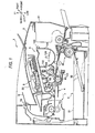
- a schematic configuration of a laser printer 1 that is an example of an image forming apparatus and a configuration for inputting driving force to a developing cartridge 100 will be first described and then configurations of the developing cartridge 100, which are characteristics of exemplary embodiments of the invention, will be described in detail.
- the directions are set on the basis of a user who uses the laser printer 1. Specifically, in FIG. 1 , the right side, the left side, the front side and the inner side are referred to as “front,” “back,” “left” and “right,” respectively. In addition, the upper and lower directions in FIG. 1 are referred to as an “upper-lower” direction.
- the laser printer 1 has a feeder unit 3 that feeds sheets S in a body casing 2 and an image forming unit 4 that forms an image on the sheet S.
- the feeder unit 3 has a sheet feeding tray 31, a sheet pressing plate 32 and a sheet feeding mechanism 33.
- the sheets S in the sheet feeding tray 31 are upwardly inclined by the sheet pressing plate 32 and supplied to the imaging forming unit 4 by the sheet feeding mechanism 4.
- the image forming unit 4 has an exposure unit 5, a developing unit 6 and a photographic fixing unit 7.
- the exposure unit 5 has a laser light emitting unit, a polygon mirror, a reflector and the like, which are not shown.
- the exposure unit 5 scans laser light emitted from the laser light emitting unit on a surface of a photosensitive drum 61 at high speed, thereby exposing the surface of the photosensitive drum 61.
- the developing unit 6 is detachably mounted to the body casing 2 by opening a front cover 21 mounted at a front side of the body casing 2 and has a drum unit 60 and a developing cartridge 100.
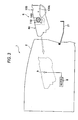
- the developing cartridge 100 is detachably mounted to the drum unit 60 and is detachably mounted to the body casing 2 with being mounted to the drum unit 60 (refer to FIG. 3 ).
- the developing cartridge 100 has a developing roller 101, a layer thickness regulating blade 102, a supply roller 103, a toner accommodating unit 104 that accommodates toner, which is an example of developer, therein and an agitator 105.
- the detailed configuration of the developing cartridge 100 will be described below.
- toner in the toner accommodating unit 104 is stirred by the agitator 105 and supplied to the developing roller 101 through the supply roller 103.
- the toner supplied on the developing roller 101 is introduced between the layer thickness regulating blade 102 and the developing roller 101 as the developing roller 101 is rotated, and is then carried, as a thin layer having a predetermined thickness, on the developing roller 101.
- the drum unit 60 has a photosensitive drum 61, a charger 62 and a transfer roller 63.
- a surface of the photosensitive drum 61 is uniformly charged by the charger 62 and then exposed by the laser light from the exposure unit 5, so that an electrostatic latent image is formed on the surface of the photosensitive drum 61.
- the toner carried on the developing roller 101 is supplied to the electrostatic latent image formed on the surface of the photosensitive drum 61, so that a toner image is formed on the surface of the photosensitive drum 61. Then, the sheet S is conveyed between the photosensitive drum 61 and the transfer roller 63, so that the toner image formed on the surface of the photosensitive drum 61 is transferred onto the sheet S.
- the photographic fixing unit 7 has a heating roller 71 and a pressing roller 72 that is opposed to the heating roller 71 and presses the heating roller 71.
- the toner image transferred on the sheet S is heat-fixed while the sheet S passes through between the heating roller 71 and the pressing roller 72.
- the sheet S on which the toner image is heat-fixed is discharged on a sheet discharge tray 22 by discharge rollers 73.
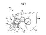
- the developing cartridge 100 has a gear mechanism 110 on a left sidewall 131 for transmitting driving force to the developing roller 101, the supply roller 103 and the agitator 105.
- the gear mechanism 110 has an input gear 112, a developing roller gear 111 and a supply roller 113, which are directly engaged with the input gear 112, and an agitator gear 115 that is engaged with the input gear 112 via an intermediate gear 114.
- the developing roller gear 111, the supply roller gear 113 and the agitator gear 115 are respectively mounted at end portions of rotational shafts so that they are integrally rotated with the developing roller 101, the supply roller 103 and the agitator 105.
- the input gear 112 is integrated with an input coupling 120 that is an example of a coupling.
- the input coupling 120 is configured so that it can be engaged with an outside output coupling 9, which will be described later, and transmits rotational force, which is input as the output coupling 9 is engaged, to the developing roller 101 and the like via the gear mechanism 110.
- the laser printer 1 has in the body casing 2 a motor 8 and the output coupling 9 that is an example of a driving input part 9 to which driving force is input from the motor 8.
- the output coupling 9 is configured to advance and retreat in the left-right direction (a direction following a second axis line A2 that will be described later) regarding the left sidewall 131 of the developing cartridge 100 mounted in the body casing 2, as the front cover 21 is opened and closed.
- the output coupling 9 is engaged to the input coupling 120 of the developing cartridge 100 and is rotated in a clockwise direction of FIG. 2 , so that the input gear 112 is rotated and thus the developing roller gear 111, the supply roller gear 113 and the agitator gear 115 are respectively rotated. Thereby, the developing roller 101, the supply roller 103 and the agitator 105 are rotated in predetermined directions.
- gear mechanism 110 mounted on the left sidewall 131 of the developing cartridge 100 is covered by a gear cover 130A (refer to FIG. 3 ), except for parts that are required to be exposed.
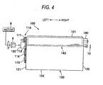
- the developing cartridge 100 has a housing 130, the developing roller 101, the input coupling 120, a moving member 140, a coil spring 150, (refer to FIG. 5 ) which is an example of a press member, and a conductive member 160, which is an example of a first engagement part.
- the housing 130 is a member that forms the toner accommodating unit 104 in which toner is accommodated and supports the developing roller 101 and the like, and has the left sidewall 131, which is an example of a first sidewall, and a right sidewall 132, which is an example of a second sidewall, such that the sidewalls face each other in the left-right direction.
- the developing roller 101 is supported at the left sidewall 131 and the right sidewall 132 and is rotatable about a rotational shaft 101 A (first axis line A1).
- a left end portion of the rotational shaft 101A protrudes from the left sidewall 131 and the developing roller gear 111 is mounted thereto so that it is integrally rotated.
- a right end portion of the rotational shaft 101 A protrudes from the right sidewall 132 and is rotatably inserted into and is electrically connected to the conductive member 160.
- the input coupling 120 is mounted on the left sidewall 131 and is configured to rotate about a second axis line A2 parallel with the first axis line A1.
- the input coupling 120 has an engagement recess 121 that is an example of an engagement part to which the output coupling 9 mounted in the body casing 2 is engaged.
- the moving member 140 is a member that connects the left sidewall 131 and the right sidewall 132 and has an extension member 141, a pushing part 170 and an electrode part 180.
- the extension member 141 is a rod-shaped member having conductivity and is inserted into through-holes 131A, 132A formed on the left sidewall 131 and the right sidewall 132, so that it is movably supported to the housing 130 along the advancing and retreating direction (left-right direction) of the output coupling 9.
- Seal members 190 for suppressing toner leakage from the inside of the housing 130 are interposed between the extension member 141 and inner circumferential surfaces of the through-holes 131A, 132A.
- the seal member 190 has a cylindrical shape and a pair of flange parts 191 that is mounted to sandwich the left sidewall 131 or right sidewall 132 at both end portions (left and right end portions) thereof regarding the extending direction of the moving member 140.
- the extension member 141 is arranged along the second axis line A2 and has a left end that protrudes from the left sidewall 131 and penetrates the input gear 112 and the input coupling 120 (a bottom 122 of the engagement recess 121).
- the pushing part 170 is a part that is pushed toward the right sidewall 132 by pushing force of the output coupling 9 engaged with the input coupling 120 and is integrated with the end portion (left end portion) of the extension member 141 at the left sidewall 131.
- the pushing part 170 has a substantially disc shape having a diameter larger than the extension member 141 of the moving member 140. Thereby, the left end portion of the moving member 140 has a T shape when seen from a plan view.
- the output coupling 9 mounted in the body casing 2 has, at a surface facing a left surface of the pushing part 170, a protrusion 91 that protrudes toward the pushing part 170.
- the protrusion 91 has such a shape that is tapered toward a leading end portion thereof, in this exemplary embodiment, a substantially hemispherical shape. The protrusion 91 is contacted to the pushing part 170 when the pushing part 170 is pushed toward the right sidewall 132 (refer to FIG. 6 ).
- the pushing part 170 protrudes more leftward from the bottom 122 of the engagement recess 121 than when the output coupling 9 is engaged with the engagement recess 121, as shown in FIG. 6 .
- the electrode part 180 is a part for applying a developing bias to the developing roller 101.
- an end portion (right end portion) of the moving member 140 (conductive extension member 141) at the right sidewall 132 forms the electrode part 180.
- the electrode part 180 contacts an apparatus-side electrode 10 mounted in the body casing 2 and supplies current, which is supplied from the apparatus-side electrode 10, to the developing roller 101 (rotational shaft 101 A) through the conductive member 160.
- the electrode part 180 protrudes from the right sidewall 132 and is inserted into the conductive member 160 before the pushing part 170 is pushed. At this time, the moving member 140 is adapted to move in the left-right direction regarding the conductive member 160 while electrically contacting the conductive member 160. In this exemplary embodiment, the right end portion (electrode part 180) of the moving member 140 protrudes slightly from the conductive member 160 before the pushing part 170 is pushed.
- the conductive member 160 is a member that is mounted to extend to the outside of the right sidewall 132 and electrically connects the developing roller 101 and the electrode part 180, and is made of a conductive resin and the like, for example.
- the conductive member 160 has a fixing part 161 that is fixed to the right sidewall 132 and into which the rotational shaft 101A of the developing roller 101 is inserted and an extension 162 that extends from a right end of the fixing part 161 and into which the electrode part 180 (moving member 140) is inserted.
- the right sidewall 132 and the extension 162 are arranged at an interval in the left-right direction and the extension 162 (conductive member 160) is engaged with a right end (one end) of the coil spring 150.
- the moving member 140 has a second engagement part 142 that is arranged between the right sidewall 132 and the extension 162 (conductive member 160) and engaged to a left end (the other end) of the coil spring 150.
- the second engagement part 142 may be formed by engaging an E ring and the like in a recess formed on a circumference of the extension member 141.
- the coil spring 150 is a member that presses the moving member 140 toward the left sidewall 131 from the right sidewall 132 and is compressed between the conductive member 160 and the second engagement part 142 with being inserted into the extension member 141. By mounting the coil spring 150, the moving member 140 can be always pressed leftward. Accordingly, before the output coupling 9 is engaged, the pushing part 170 can protrude further from the bottom 122 of the engagement recess 121 than after the output coupling 9 has been engaged (refer to FIG. 6 ).
- the moving member 140 is always pressed leftward by the coil spring 150, so that the protruding of the electrode part 180 from the housing 130 (conductive member 160) can be made to be small. Thereby, it is possible to suppress the electrode part 180 from being damaged or broken when handling the developing cartridge 100. In addition, when attaching and detaching the developing cartridge 100 to and from the body casing 2, the electrode part 180 is difficult to slidingly contact the apparatus-side electrode 10, so that it is possible to suppress the wear of the apparatus-side electrode 10.
- the output coupling 9 is moved toward the developing cartridge 100 and is engaged to the input coupling 120 (engagement recess 121), as shown in FIG. 4 .
- the protrusion 91 of the output coupling 9 is contacted to the pushing part 170 and the output coupling 9 is further moved toward the right sidewall 132, so that the pushing part 170 is pushed by the output coupling 9.
- the moving member 140 is wholly moved toward the right sidewall 132, so that the electrode part 80 protrudes from the right sidewall 132 more (conductive member 160) than before the pushing part 170 is pushed (refer to FIG. 5 ).
- the electrode part 180 is contacted to the apparatus-side electrode 10, so that developing bias can be applied to the developing roller 101.
- the moving member 140 is entirely moved to the left sidewall 131 by restoring force of the coil spring 150 (refer to FIG. 5 ).
- the electrode part 180 is separated from the apparatus-side electrode 10 and is returned to its original position at which the protrusion from the housing 130 thereof (conductive member 160) is small.
- the electrode part 180 since it is possible to suppress the electrode part 180 from being damaged when handling the developing cartridge 100 such as when conveying or attaching/detaching the developing cartridge, it is possible to protect the electrode part 180.
- the electrode part 180 when attaching and detaching the developing cartridge 100 to and from the body casing 2, the electrode part 180 is difficult to slidingly contact the apparatus-side electrode 10. Therefore, it is possible to suppress the wear of the apparatus-side electrode 10, so that it is possible to protect the apparatus-side electrode 10.
- the pushing part 170 protrudes from the bottom 122 of the engagement recess 121 more before the output coupling 9 is engaged than after the output coupling 9 is engaged, it is possible to securely push the pushing part 170 into engagement of the output coupling 9.
- the moving member 140 since the moving member 140 is mounted to penetrate the input coupling 120, it is possible to push the pushing part 170 more securely, compared to a configuration in which the pushing part provided at the outside of the input coupling 120 (engagement recess 121) is pushed by the output coupling 9.
- the output coupling 9 has the protrusion 91 at the surface facing the pushing part 170 and the protrusion 91 is contacted to the pushing part 170 when pushing the pushing part 170 toward the right sidewall 132, it is possible to make the contact area between the output coupling 9 and the moving member 140 small. Thereby, since it is possible to favorably rotate the output coupling 9, it is also possible to favorably rotate the developing roller 101 and the like.
- the pushing part 170 since the pushing part 170 has the shape having the diameter larger than another part (extension member 141) of the moving member 140, it is possible to securely contact the output coupling 9 to the moving member 140 (pushing part 170) while making the contact area between the output coupling 9 and the moving member 140 small. Thereby, it is possible to securely push the pushing part 170.
- a developing cartridge 200 of this exemplary embodiment includes a developing roller 201, which has a rotational shaft 240, which is used as the moving member.
- An input coupling 220 (coupling) is integrated with a left end portion of the rotational shaft 240 (moving member).
- the rotational shaft 240 (developing roller 201) is supported by the left sidewall 131 (housing 130) so that it can be moved along the advancing and retreating direction (left-right direction) of the output coupling 9.
- the output coupling 9 is engaged with the input coupling 220 and the input coupling 220 is pushed by the output coupling 9, as shown in FIG. 7B , so that the rotational shaft 240 (moving member) is moved toward the right sidewall 132, which is not shown.
- the input coupling 220 is integrated with the rotational shaft 240 (moving member), it is not necessary to separately provide the pushing part and thus a configuration of the developing cartridge 200 is simplified.
- the rotational shaft 240 of the developing roller 201 is used as the moving member, it is not necessary to provide the moving member 140, the through-holes 131A, 132A, the seal members 190 and the like, which are provided in the first exemplary embodiment. Further, although not shown, since a right end portion (electrode part) of the rotational shaft 240 can be directly contacted to the apparatus-side electrode, the conductive member 160 of the first exemplary embodiment is not required. Also by these configurations, it is possible to simplify the configuration of the developing cartridge 200.
- a developing cartridge 300 of this exemplary embodiment has an input coupling 320 and a moving member 340, which are separately mounted and are arranged on substantially the same axis line.
- the moving member 340 has an extension member 341, a pushing part 370 and an electrode part that is not shown, and is supported by the housing 130 so that it can be moved along the left-right direction.
- the input coupling 320 is integrated with the input gear 112 that is directly engaged with the developing roller gear 111, and is arranged at the left side of the pushing part 370 with being spaced from the moving member 340 before the output coupling 9 is engaged.
- the input coupling 320 is mounted to the left sidewall 131 (housing 130) so that it can be moved along the advancing and retreating direction (left-right direction) of the output coupling 9.
- the input coupling 320 is pushed by the pushing force of the output coupling 9, so that the moving member 340 is moved toward the right sidewall 132 (not shown) integrally with the input coupling 320.
- the member (for example, input coupling 320) different from the moving member 340 may be interposed between the output coupling 9 (driving input part) and the moving member 340 inasmuch as the pushing force from the output coupling 9 (driving input part) is transmitted to the moving member 340.
- a protrusion that protrudes toward the pushing part 370 may be provided on a surface facing the pushing part 370 of the input coupling 320.
- seal members 490 are provided between the extension member 141 of the moving member 140 and the inner circumferential surfaces of the through-holes 131A, 132A into which the extension member 141 is inserted.
- the seal member 490 has a cylindrical shape and a pair of flange parts 191 that are mounted to sandwich the left sidewall 131 or right sidewall 132 at both left and right end portions thereof.
- the seal members 191 are configured in such a way that a length L regarding the extending direction (left-right direction) of the extension member 140 is larger than a moving distance D when the moving member 140 is moved toward the right sidewall 132.
- the toner T does not leaked to the outside through the through-hole 132A even when before the pushing part 170 is pushed toner T attached to the extension member 141 (adjacent to the right sidewall 132) is introduced between the extension member 141 and the seal member 490 as the moving member 140 is moved.
- the toner T attached to the extension member 141 is displaced rightward by the moving distance D of the moving member 140.
- the toner T attached to the extension member 141 is displaced rightward by the moving distance D of the moving member 140.
- the length L of the seal member 490 is larger than the moving distance D, the toner stays between the extension member 141 and the seal member 490.
- the seal members 490 of this exemplary embodiment have the flange parts 191, like the seal members 190 of the first exemplary embodiment, the seal members are not well dropped out of the through-holes 131A, 132A.
- the housing 130 has a cylinder-shaped member 590 that is mounted from the left sidewall 131 to the right sidewall 132 and the moving member 140 is inserted into the cylinder-shaped member 590 and is supported so that it can be moved along the advancing and retreating direction (left-right direction) of the output coupling 9.
- the shape of the cylinder-shaped member 590 is not particularly limited and may be cylindrical or polygonal.
- the moving member 140 may be inserted with being closely contacted so that it can be moved in the cylinder-shaped member 590, or may be inserted with a play into the cylinder-shaped member 590.
- the moving member 140 was integrated with the pushing part 170 and the electrode part 180, i.e., one moving member 140 has been described.
- the invention is not limited thereto.
- the moving member of the invention may be configured with two or more members.
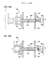
- a moving member 140' may have a rod-shaped extension member 141' made of an insulating resin and the like and an electrode part 180' (metal rod or metal plate) that is made of a member different from the extension member 141' and is fixed to a right end portion of the extension member 141'.
- the extension member 141' may be configured by a plurality of short rod-shaped members, each of which is connected to each other.
- the electrode part that is a different member may not be fixed to the extension member.
- an extension member 641 and an electrode plate 680 that is an example of the electrode part, which forms a moving member 640 may be spaced from each other before the pushing part is pushed.
- the pushing part is pushed by the pushing force of the output coupling 9 (not shown) and the extension member 641 is thus moved toward the right sidewall 132
- the extension member 641 is contacted to the electrode plate 680.
- FIG. 12B the extension member 641 and the electrode plate 680 are integrally moved, so that the electrode plate 680 is contacted to the apparatus-side electrode 10.
- the pushing part may be also configured in the same method as the electrode part.
- the coil spring 150 has been exemplified as the press member.
- the invention is not limited thereto.
- a pulling spring or plate spring may be adopted.
- a member having elasticity such as a foam elastic member may be adopted.
- the developing cartridge may not have the press member.
- the main body of the image forming apparatus may be provided with a member that presses the moving member from the second sidewall toward the first sidewall.
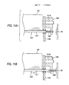
- an apparatus-side electrode 10' may be configured to serve as a plate spring. According to this configuration, as the pushing of the drive input part is released, the moving member 140 may be pressed from the second sidewall to the first sidewall by the restoring force of the apparatus-side electrode 10' (plate spring).
- the moving member 140 is configured to penetrate the input coupling 120 (coupling).
- the invention is not limited thereto.
- the moving member (pushing part) may be arranged at the outside of the input coupling 120.
- the engagement recess 121 has been exemplified as the engagement part of the coupling.
- the invention is not limited thereto.
- a convex engagement part that is engaged with the drive input part may also be possible.
- the surface having the protrusion may be configured as the engagement part.
- the rod-shaped straight moving member 140 extending in a direction following the second axis line A2 has been shown.
- the invention is not limited thereto.
- a moving member 140A having a substantially U shape may be arranged in the housing 130. According to this configuration, it is possible to provide the moving member 140A while avoiding the members in the housing 130.
- a part of a moving member 140B may have a plate shape. According to this configuration, since the part having a plate shape can be used as a wall dividing a part in which the developing roller, the supply roller and the like are provided and a part in which toner is accommodated, it is possible to make the developing cartridge smaller.
- a moving member 140C having a spiral shape may be arranged in the housing 130.
- the moving member 140C can be configured to rotate by providing the input coupling 120 to a left end portion of the moving member, for example, so that the moving member can be made to serve as an auger stirring and conveying toner in the housing 130.
- a moving member 140D may be arranged in such as way that the pushing part 170 and the electrode part 180 are inconsistent with each other when seen from the advancing and retreating direction of the output coupling 9.
- the invention can be applied to an image forming apparatus in which the apparatus-side electrode 10 is not provided on the second axis line A2.
- it is possible to increase a degree of arrangement freedom of the output coupling 9 and the apparatus-side electrode 10. Therefore, it is possible to make an image forming apparatus small.
- the conductive member 160 has been shown as the first engagement part.
- the first engagement part may be provided separately from the conductive member 160.
- the second engagement part 142 has been formed by engaging the E ring and the like in the recess of the extension member 141.
- the invention is not limited thereto.
- the second engagement part (protrusion and the like) may be directly formed at the moving member (extension member 141).
- the moving member 140 extends in the housing 130 so that it connects the left sidewall 131 (first sidewall) and the right sidewall 132 (second sidewall).
- the invention is not limited thereto.
- the moving member may extend at the outside of the housing (a part in which developer is accommodated) so that it connects the first sidewall and the second sidewall.
- the protrusion 91 provided to the output coupling 9 (drive input part) has a substantially hemispherical shape.
- the shape of the protrusion is not particularly limited inasmuch as it is tapered toward the leading end thereof.
- the protrusion may have a substantially triangular shape.
- the input coupling 120 and the output coupling 9 have been shown as the coupling and the drive input part, respectively.
- the invention is not limited thereto.
- the coupling and the drive input part may have other configurations without departing from the scope of the invention.
- the left sidewall 131 and the right sidewall 132 have been shown as the first sidewall and the second sidewall, respectively.
- the invention is not limited thereto.
- the left and the right of the first sidewall and the second sidewall may be opposite to the exemplary embodiments.
- the right end portion (electrode part 180) of the moving member 140 slightly protrudes from the conductive member 160 (outer surface of the developing cartridge) before the pushing part 170 is pushed.
- the invention is not limited thereto.
- the right end portion (electrode part 180) of the moving member 140 may be flush with a right end face of the conductive member 160 (outer surface of the developing cartridge) before the pushing part 170 is pushed.
- the right end portion (electrode part 180) of the moving member 140 may be inserted into the right end face of the conductive member 160 (outer surface of the developing cartridge) before the pushing part 170 is pushed.
- the developing cartridge 100 that is detachably mounted to the drum unit 60 has been shown.
- the invention is not limited thereto.
- the developing cartridge of the invention may be a cartridge in which the drum unit 60 and the developing cartridge 100 of the first exemplary embodiment are undetachably integrated.
- the black-white laser printer 1 has been shown as the image forming apparatus.
- the invention is not limited thereto.
- a color printer is also possible.
- the image forming apparatus is not limited to the printer and may be a copier or complex machine.
Landscapes
- Physics & Mathematics (AREA)
- General Physics & Mathematics (AREA)
- Engineering & Computer Science (AREA)
- Computer Vision & Pattern Recognition (AREA)
- Dry Development In Electrophotography (AREA)
- Electrophotography Configuration And Component (AREA)
Applications Claiming Priority (1)
| Application Number | Priority Date | Filing Date | Title |
|---|---|---|---|
| JP2010037768A JP4905567B2 (ja) | 2010-02-23 | 2010-02-23 | 現像カートリッジおよび画像形成装置 |
Publications (3)
| Publication Number | Publication Date |
|---|---|
| EP2365402A2 true EP2365402A2 (de) | 2011-09-14 |
| EP2365402A3 EP2365402A3 (de) | 2012-11-21 |
| EP2365402B1 EP2365402B1 (de) | 2015-11-04 |
Family
ID=43948323
Family Applications (1)
| Application Number | Title | Priority Date | Filing Date |
|---|---|---|---|
| EP11001509.6A Not-in-force EP2365402B1 (de) | 2010-02-23 | 2011-02-23 | Entwicklungskartusche und Bilderzeugungsvorrichtung |
Country Status (4)
| Country | Link |
|---|---|
| US (2) | US8594526B2 (de) |
| EP (1) | EP2365402B1 (de) |
| JP (1) | JP4905567B2 (de) |
| CN (1) | CN102163029B (de) |
Cited By (4)
| Publication number | Priority date | Publication date | Assignee | Title |
|---|---|---|---|---|
| EP2592494A3 (de) * | 2011-08-31 | 2014-09-24 | Brother Kogyo Kabushiki Kaisha | Kartusche |
| US8995866B2 (en) | 2011-08-31 | 2015-03-31 | Brother Kogyo Kabushiki Kaisha | Cartridge having coupling member and detection body |
| US9008522B2 (en) | 2011-08-31 | 2015-04-14 | Brother Kogyo Kabushiki Kaisha | Developing cartridge having housing and developing roller |
| US9195207B2 (en) | 2011-08-31 | 2015-11-24 | Brother Kogyo Kabushiki Kaisha | Cartridge having detection body |
Families Citing this family (23)
| Publication number | Priority date | Publication date | Assignee | Title |
|---|---|---|---|---|
| JP4905567B2 (ja) * | 2010-02-23 | 2012-03-28 | ブラザー工業株式会社 | 現像カートリッジおよび画像形成装置 |
| JP5868079B2 (ja) | 2011-09-05 | 2016-02-24 | キヤノン株式会社 | カートリッジおよび画像形成装置 |
| JP6056420B2 (ja) * | 2012-11-27 | 2017-01-11 | ブラザー工業株式会社 | 感光体カートリッジ |
| JP6136373B2 (ja) * | 2013-03-04 | 2017-05-31 | ブラザー工業株式会社 | 現像カートリッジ |
| JP6136372B2 (ja) * | 2013-03-04 | 2017-05-31 | ブラザー工業株式会社 | 現像カートリッジ |
| JP6136374B2 (ja) * | 2013-03-04 | 2017-05-31 | ブラザー工業株式会社 | 現像カートリッジ |
| WO2014141447A1 (ja) * | 2013-03-14 | 2014-09-18 | ブラザー工業株式会社 | 現像カートリッジ |
| WO2014141444A1 (ja) * | 2013-03-14 | 2014-09-18 | ブラザー工業株式会社 | 現像カートリッジ |
| WO2014141445A1 (ja) * | 2013-03-14 | 2014-09-18 | ブラザー工業株式会社 | 現像カートリッジ |
| WO2014141446A1 (ja) * | 2013-03-14 | 2014-09-18 | ブラザー工業株式会社 | 現像カートリッジ |
| JP6136603B2 (ja) | 2013-06-07 | 2017-05-31 | ブラザー工業株式会社 | カートリッジ |
| US9519243B2 (en) | 2014-06-02 | 2016-12-13 | Lexmark International, Inc. | Replaceable unit for an image forming device having magnets of varying angular offset for toner level sensing |
| US9389582B2 (en) | 2014-06-02 | 2016-07-12 | Lexmark International, Inc. | Replaceable unit for an image forming device having magnets of varying angular offset for toner level sensing |
| CN116184786B (zh) * | 2017-12-13 | 2026-01-27 | 佳能株式会社 | 盒与图像形成装置 |
| CN108535989B (zh) * | 2018-06-21 | 2021-02-19 | 珠海市拓佳科技有限公司 | 处理盒 |
| US10429765B1 (en) | 2018-07-05 | 2019-10-01 | Lexmark International, Inc. | Toner container for an image forming device having magnets of varying angular offset for toner level sensing |
| US10474060B1 (en) | 2018-07-05 | 2019-11-12 | Lexmark International, Inc. | Toner level sensing using rotatable magnets having varying angular offset |
| US10451997B1 (en) | 2018-07-20 | 2019-10-22 | Lexmark International, Inc. | Toner level detection measuring an orientation of a rotatable magnet having a varying orientation relative to a pivot axis |
| US10345736B1 (en) | 2018-07-20 | 2019-07-09 | Lexmark International, Inc. | Toner level detection measuring a radius of a rotatable magnet |
| US10451998B1 (en) | 2018-07-20 | 2019-10-22 | Lexmark International, Inc. | Toner level detection measuring an orientation of a rotatable magnet having a varying radius |
| JP7131681B2 (ja) * | 2019-09-18 | 2022-09-06 | ブラザー工業株式会社 | 現像カートリッジ |
| US11662686B2 (en) * | 2020-12-11 | 2023-05-30 | Canon Kabushiki Kaisha | Oldham coupling and image forming apparatus |
| WO2023109723A1 (zh) | 2021-12-17 | 2023-06-22 | 江西亿铂电子科技有限公司 | 一种显影盒 |
Family Cites Families (16)
| Publication number | Priority date | Publication date | Assignee | Title |
|---|---|---|---|---|
| JPH0342156A (ja) * | 1989-07-05 | 1991-02-22 | Sumitomo Metal Ind Ltd | 金属の連続鋳造方法及びその装置 |
| JPH0651629A (ja) * | 1992-07-30 | 1994-02-25 | Canon Inc | 現像装置 |
| JP3787441B2 (ja) * | 1998-10-08 | 2006-06-21 | キヤノン株式会社 | 電子写真画像形成装置 |
| JP2000275967A (ja) | 1999-03-29 | 2000-10-06 | Canon Inc | プロセスカートリッジ及び電子写真画像形成装置 |
| JP2001003944A (ja) * | 1999-06-22 | 2001-01-09 | Kyocera Mita Corp | シール部材 |
| JP4250294B2 (ja) | 2000-02-16 | 2009-04-08 | キヤノン株式会社 | カラー電子写真画像形成装置及びプロセスカートリッジ |
| JP3997817B2 (ja) | 2002-04-02 | 2007-10-24 | ブラザー工業株式会社 | 現像装置および画像形成装置 |
| JP2005017758A (ja) * | 2003-06-26 | 2005-01-20 | Ricoh Co Ltd | 画像形成装置 |
| JP4387932B2 (ja) * | 2003-12-09 | 2009-12-24 | キヤノン株式会社 | プロセスカートリッジ及び電子写真画像形成装置 |
| EP1640820B1 (de) | 2004-08-06 | 2011-12-14 | Brother Kogyo Kabushiki Kaisha | Entwicklungsbehälter mit einem vorstehenden Teil aussen am Gehäuse |
| JP4348625B2 (ja) | 2004-08-06 | 2009-10-21 | ブラザー工業株式会社 | プロセスカートリッジ、感光体カートリッジ、現像カートリッジおよび画像形成装置 |
| JP4341619B2 (ja) | 2005-07-08 | 2009-10-07 | ブラザー工業株式会社 | 現像カートリッジ |
| JP4665928B2 (ja) * | 2007-03-27 | 2011-04-06 | ブラザー工業株式会社 | カートリッジおよび画像形成装置 |
| JP2008298804A (ja) * | 2007-05-29 | 2008-12-11 | Fuji Xerox Co Ltd | 駆動伝達機構、及び画像形成装置 |
| JP2009098316A (ja) | 2007-10-16 | 2009-05-07 | Fuji Xerox Co Ltd | 給電装置および画像形成装置 |
| JP4905567B2 (ja) * | 2010-02-23 | 2012-03-28 | ブラザー工業株式会社 | 現像カートリッジおよび画像形成装置 |
-
2010
- 2010-02-23 JP JP2010037768A patent/JP4905567B2/ja not_active Expired - Fee Related
-
2011
- 2011-02-23 CN CN201110048547.5A patent/CN102163029B/zh not_active Expired - Fee Related
- 2011-02-23 US US13/033,486 patent/US8594526B2/en active Active
- 2011-02-23 EP EP11001509.6A patent/EP2365402B1/de not_active Not-in-force
-
2013
- 2013-11-25 US US14/088,952 patent/US8831462B2/en active Active
Non-Patent Citations (1)
| Title |
|---|
| None |
Cited By (37)
| Publication number | Priority date | Publication date | Assignee | Title |
|---|---|---|---|---|
| EP2592494A3 (de) * | 2011-08-31 | 2014-09-24 | Brother Kogyo Kabushiki Kaisha | Kartusche |
| US8995846B2 (en) | 2011-08-31 | 2015-03-31 | Brother Kogyo Kabushiki Kaisha | Cartridge mountable on image-forming apparatus |
| US8995866B2 (en) | 2011-08-31 | 2015-03-31 | Brother Kogyo Kabushiki Kaisha | Cartridge having coupling member and detection body |
| US9008522B2 (en) | 2011-08-31 | 2015-04-14 | Brother Kogyo Kabushiki Kaisha | Developing cartridge having housing and developing roller |
| US9195207B2 (en) | 2011-08-31 | 2015-11-24 | Brother Kogyo Kabushiki Kaisha | Cartridge having detection body |
| US9207632B2 (en) | 2011-08-31 | 2015-12-08 | Brother Kogyo Kabushiki Kaisha | Developing cartridge provided with detection body |
| US9395684B2 (en) | 2011-08-31 | 2016-07-19 | Brother Kogyo Kabushiki Kaisha | Developing cartridge having coupling and developing roller |
| US9494914B2 (en) | 2011-08-31 | 2016-11-15 | Brother Kogyo Kabushiki Kaisha | Developing cartridge including developing roller having developing roller shaft |
| US9529319B2 (en) | 2011-08-31 | 2016-12-27 | Brother Kogyo Kabushiki Kaisha | Developing cartridge having coupling and developing roller |
| US9557684B2 (en) | 2011-08-31 | 2017-01-31 | Brother Kogyo Kabushiki Kaisha | Developing cartridge including developing roller having developing roller shaft |
| US9575460B2 (en) | 2011-08-31 | 2017-02-21 | Brother Kogyo Kabushiki Kaisha | Developer cartridge having developing roller and electrode |
| US9785093B2 (en) | 2011-08-31 | 2017-10-10 | Brother Kogyo Kabushiki Kaisha | Developing cartridge including developing roller having developing roller shaft |
| US9846387B2 (en) | 2011-08-31 | 2017-12-19 | Brother Kogyo Kabushiki Kaisha | Developing cartridge having coupling and developing roller |
| US10303088B2 (en) | 2011-08-31 | 2019-05-28 | Brother Kogyo Kabushiki Kaisha | Developing cartridge including developing roller and gear |
| US10310413B2 (en) | 2011-08-31 | 2019-06-04 | Brother Kogyo Kabushiki Kaisha | Developing cartridge including developing roller having developing roller shaft |
| US10310414B2 (en) | 2011-08-31 | 2019-06-04 | Brother Kogyo Kabushiki Kaisha | Developing cartridge including housing and gear |
| US10496011B2 (en) | 2011-08-31 | 2019-12-03 | Brother Kogyo Kabushiki Kaisha | Developing cartridge having coupling and developing roller |
| US10520855B2 (en) | 2011-08-31 | 2019-12-31 | Brother Kogyo Kabushiki Kaisha | Developing cartridge having coupling and developing roller |
| US10571828B2 (en) | 2011-08-31 | 2020-02-25 | Brother Kogyo Kabushiki Kaisha | Developing cartridge including developing roller and coupling |
| US10670994B2 (en) | 2011-08-31 | 2020-06-02 | Brother Kogyo Kabushiki Kaisha | Developing cartridge including housing and gear |
| US10768550B2 (en) | 2011-08-31 | 2020-09-08 | Brother Kogyo Kabushiki Kaisha | Developing cartridge including developing roller and coupling |
| US10921732B2 (en) | 2011-08-31 | 2021-02-16 | Brother Kogyo Kabushiki Kaisha | Developing cartridge having coupling and developing roller |
| US11022912B2 (en) | 2011-08-31 | 2021-06-01 | Brother Kogyo Kabushiki Kaisha | Developing cartridge having coupling and developing roller |
| US11022936B2 (en) | 2011-08-31 | 2021-06-01 | Brother Kogyo Kabushiki Kaisha | Developing cartridge including developing roller and coupling |
| US11042105B2 (en) | 2011-08-31 | 2021-06-22 | Brother Kogyo Kabushiki Kaisha | Developing cartridge including housing and gear |
| DE112012003620B4 (de) | 2011-08-31 | 2021-11-11 | Brother Kogyo Kabushiki Kaisha | Kartusche |
| US11385571B2 (en) | 2011-08-31 | 2022-07-12 | Brother Kogyo Kabushiki Kaisha | Developing cartridge including housing and gear |
| US11409210B2 (en) | 2011-08-31 | 2022-08-09 | Brother Kogyo Kabushiki Kaisha | Developing cartridge having coupling and developing roller |
| US11687016B2 (en) | 2011-08-31 | 2023-06-27 | Brother Kogyo Kabushiki Kaisha | Developing cartridge having coupling and developing roller |
| US11693334B2 (en) | 2011-08-31 | 2023-07-04 | Brother Kogyo Kabushiki Kaisha | Developing cartridge having coupling and developing roller |
| US11747765B2 (en) | 2011-08-31 | 2023-09-05 | Brother Kogyo Kabushiki Kaisha | Developing cartridge including developing roller and coupling |
| US12007707B2 (en) | 2011-08-31 | 2024-06-11 | Brother Kogyo Kabushiki Kaisha | Developing cartridge including housing and gear |
| US12092992B2 (en) | 2011-08-31 | 2024-09-17 | Brother Kogyo Kabushiki Kaisha | Developing cartridge including developing roller and coupling |
| US12117745B2 (en) | 2011-08-31 | 2024-10-15 | Brother Kogyo Kabushiki Kaisha | Developing cartridge having coupling and developing roller |
| US12321110B2 (en) | 2011-08-31 | 2025-06-03 | Brother Kogyo Kabushiki Kaisha | Developing cartridge having coupling and developing roller |
| US12379680B2 (en) | 2011-08-31 | 2025-08-05 | Brother Kogyo Kabushiki Kaisha | Developing cartridge having coupling and developing roller |
| US12474653B2 (en) | 2011-08-31 | 2025-11-18 | Brother Kogyo Kabushiki Kaisha | Developing cartridge having coupling and developing roller |
Also Published As
| Publication number | Publication date |
|---|---|
| US8831462B2 (en) | 2014-09-09 |
| US20140079430A1 (en) | 2014-03-20 |
| CN102163029B (zh) | 2014-08-13 |
| EP2365402A3 (de) | 2012-11-21 |
| JP2011175034A (ja) | 2011-09-08 |
| EP2365402B1 (de) | 2015-11-04 |
| US20110206407A1 (en) | 2011-08-25 |
| CN102163029A (zh) | 2011-08-24 |
| JP4905567B2 (ja) | 2012-03-28 |
| US8594526B2 (en) | 2013-11-26 |
Similar Documents
| Publication | Publication Date | Title |
|---|---|---|
| US8831462B2 (en) | Developing cartridge and image forming apparatus for protecting an electrode from damage during handling | |
| JP6776567B2 (ja) | 画像形成装置 | |
| CN113176720B (zh) | 显影盒 | |
| JP7747146B2 (ja) | 現像カートリッジ | |
| US20220357701A1 (en) | Developing cartridge providing layout of electrodes and detection gear | |
| JP4910793B2 (ja) | 現像剤カートリッジ | |
| US10962905B1 (en) | Seal for an electrophotograhic image forming device | |
| US8977170B2 (en) | Image forming apparatus, toner case and drive transmission mechanism | |
| EP3966637B1 (de) | Elektrische kontakte für tonerpatrone | |
| JP7803327B2 (ja) | ドラムカートリッジおよび現像カートリッジ | |
| JP2021005112A (ja) | 画像形成装置 | |
| JP2020160223A (ja) | 現像カートリッジ | |
| JP2022086711A (ja) | 現像カートリッジ | |
| US8538291B2 (en) | Developing cartridge | |
| US9152082B2 (en) | Cartridge having contact member to mitigate damage to cartridge frame | |
| JP2020160222A (ja) | 現像カートリッジ | |
| CN110209024B (zh) | 显影盒 | |
| JP2021167917A (ja) | 現像カートリッジ | |
| CN113614650B (zh) | 鼓盒和显影盒 | |
| CN100514202C (zh) | 旋转力控制装置及包括该装置的成像装置 | |
| HK40060731B (en) | Toner cartridge electrical contacts | |
| HK40060731A (en) | Toner cartridge electrical contacts |
Legal Events
| Date | Code | Title | Description |
|---|---|---|---|
| PUAI | Public reference made under article 153(3) epc to a published international application that has entered the european phase |
Free format text: ORIGINAL CODE: 0009012 |
|
| AK | Designated contracting states |
Kind code of ref document: A2 Designated state(s): AL AT BE BG CH CY CZ DE DK EE ES FI FR GB GR HR HU IE IS IT LI LT LU LV MC MK MT NL NO PL PT RO RS SE SI SK SM TR |
|
| AX | Request for extension of the european patent |
Extension state: BA ME |
|
| RIN1 | Information on inventor provided before grant (corrected) |
Inventor name: MUSHIKA, MOTOAKI Inventor name: FUKAMACHI, YASUO |
|
| PUAL | Search report despatched |
Free format text: ORIGINAL CODE: 0009013 |
|
| AK | Designated contracting states |
Kind code of ref document: A3 Designated state(s): AL AT BE BG CH CY CZ DE DK EE ES FI FR GB GR HR HU IE IS IT LI LT LU LV MC MK MT NL NO PL PT RO RS SE SI SK SM TR |
|
| AX | Request for extension of the european patent |
Extension state: BA ME |
|
| RIC1 | Information provided on ipc code assigned before grant |
Ipc: G03G 21/16 20060101ALI20121017BHEP Ipc: G03G 21/18 20060101AFI20121017BHEP |
|
| 17P | Request for examination filed |
Effective date: 20130521 |
|
| GRAP | Despatch of communication of intention to grant a patent |
Free format text: ORIGINAL CODE: EPIDOSNIGR1 |
|
| INTG | Intention to grant announced |
Effective date: 20150522 |
|
| GRAS | Grant fee paid |
Free format text: ORIGINAL CODE: EPIDOSNIGR3 |
|
| GRAA | (expected) grant |
Free format text: ORIGINAL CODE: 0009210 |
|
| AK | Designated contracting states |
Kind code of ref document: B1 Designated state(s): AL AT BE BG CH CY CZ DE DK EE ES FI FR GB GR HR HU IE IS IT LI LT LU LV MC MK MT NL NO PL PT RO RS SE SI SK SM TR |
|
| REG | Reference to a national code |
Ref country code: GB Ref legal event code: FG4D |
|
| REG | Reference to a national code |
Ref country code: CH Ref legal event code: EP |
|
| REG | Reference to a national code |
Ref country code: AT Ref legal event code: REF Ref document number: 759620 Country of ref document: AT Kind code of ref document: T Effective date: 20151115 |
|
| REG | Reference to a national code |
Ref country code: IE Ref legal event code: FG4D |
|
| REG | Reference to a national code |
Ref country code: DE Ref legal event code: R096 Ref document number: 602011021082 Country of ref document: DE |
|
| REG | Reference to a national code |
Ref country code: FR Ref legal event code: PLFP Year of fee payment: 6 |
|
| REG | Reference to a national code |
Ref country code: NL Ref legal event code: MP Effective date: 20151104 |
|
| REG | Reference to a national code |
Ref country code: LT Ref legal event code: MG4D |
|
| REG | Reference to a national code |
Ref country code: AT Ref legal event code: MK05 Ref document number: 759620 Country of ref document: AT Kind code of ref document: T Effective date: 20151104 |
|
| PG25 | Lapsed in a contracting state [announced via postgrant information from national office to epo] |
Ref country code: NL Free format text: LAPSE BECAUSE OF FAILURE TO SUBMIT A TRANSLATION OF THE DESCRIPTION OR TO PAY THE FEE WITHIN THE PRESCRIBED TIME-LIMIT Effective date: 20151104 Ref country code: NO Free format text: LAPSE BECAUSE OF FAILURE TO SUBMIT A TRANSLATION OF THE DESCRIPTION OR TO PAY THE FEE WITHIN THE PRESCRIBED TIME-LIMIT Effective date: 20160204 Ref country code: LT Free format text: LAPSE BECAUSE OF FAILURE TO SUBMIT A TRANSLATION OF THE DESCRIPTION OR TO PAY THE FEE WITHIN THE PRESCRIBED TIME-LIMIT Effective date: 20151104 Ref country code: ES Free format text: LAPSE BECAUSE OF FAILURE TO SUBMIT A TRANSLATION OF THE DESCRIPTION OR TO PAY THE FEE WITHIN THE PRESCRIBED TIME-LIMIT Effective date: 20151104 Ref country code: IT Free format text: LAPSE BECAUSE OF FAILURE TO SUBMIT A TRANSLATION OF THE DESCRIPTION OR TO PAY THE FEE WITHIN THE PRESCRIBED TIME-LIMIT Effective date: 20151104 Ref country code: IS Free format text: LAPSE BECAUSE OF FAILURE TO SUBMIT A TRANSLATION OF THE DESCRIPTION OR TO PAY THE FEE WITHIN THE PRESCRIBED TIME-LIMIT Effective date: 20160304 Ref country code: HR Free format text: LAPSE BECAUSE OF FAILURE TO SUBMIT A TRANSLATION OF THE DESCRIPTION OR TO PAY THE FEE WITHIN THE PRESCRIBED TIME-LIMIT Effective date: 20151104 |
|
| PG25 | Lapsed in a contracting state [announced via postgrant information from national office to epo] |
Ref country code: AT Free format text: LAPSE BECAUSE OF FAILURE TO SUBMIT A TRANSLATION OF THE DESCRIPTION OR TO PAY THE FEE WITHIN THE PRESCRIBED TIME-LIMIT Effective date: 20151104 Ref country code: FI Free format text: LAPSE BECAUSE OF FAILURE TO SUBMIT A TRANSLATION OF THE DESCRIPTION OR TO PAY THE FEE WITHIN THE PRESCRIBED TIME-LIMIT Effective date: 20151104 Ref country code: LV Free format text: LAPSE BECAUSE OF FAILURE TO SUBMIT A TRANSLATION OF THE DESCRIPTION OR TO PAY THE FEE WITHIN THE PRESCRIBED TIME-LIMIT Effective date: 20151104 Ref country code: PT Free format text: LAPSE BECAUSE OF FAILURE TO SUBMIT A TRANSLATION OF THE DESCRIPTION OR TO PAY THE FEE WITHIN THE PRESCRIBED TIME-LIMIT Effective date: 20160304 Ref country code: GR Free format text: LAPSE BECAUSE OF FAILURE TO SUBMIT A TRANSLATION OF THE DESCRIPTION OR TO PAY THE FEE WITHIN THE PRESCRIBED TIME-LIMIT Effective date: 20160205 Ref country code: PL Free format text: LAPSE BECAUSE OF FAILURE TO SUBMIT A TRANSLATION OF THE DESCRIPTION OR TO PAY THE FEE WITHIN THE PRESCRIBED TIME-LIMIT Effective date: 20151104 Ref country code: SE Free format text: LAPSE BECAUSE OF FAILURE TO SUBMIT A TRANSLATION OF THE DESCRIPTION OR TO PAY THE FEE WITHIN THE PRESCRIBED TIME-LIMIT Effective date: 20151104 Ref country code: RS Free format text: LAPSE BECAUSE OF FAILURE TO SUBMIT A TRANSLATION OF THE DESCRIPTION OR TO PAY THE FEE WITHIN THE PRESCRIBED TIME-LIMIT Effective date: 20151104 Ref country code: BE Free format text: LAPSE BECAUSE OF NON-PAYMENT OF DUE FEES Effective date: 20160229 |
|
| PG25 | Lapsed in a contracting state [announced via postgrant information from national office to epo] |
Ref country code: CZ Free format text: LAPSE BECAUSE OF FAILURE TO SUBMIT A TRANSLATION OF THE DESCRIPTION OR TO PAY THE FEE WITHIN THE PRESCRIBED TIME-LIMIT Effective date: 20151104 |
|
| REG | Reference to a national code |
Ref country code: DE Ref legal event code: R097 Ref document number: 602011021082 Country of ref document: DE |
|
| PG25 | Lapsed in a contracting state [announced via postgrant information from national office to epo] |
Ref country code: RO Free format text: LAPSE BECAUSE OF FAILURE TO SUBMIT A TRANSLATION OF THE DESCRIPTION OR TO PAY THE FEE WITHIN THE PRESCRIBED TIME-LIMIT Effective date: 20151104 Ref country code: DK Free format text: LAPSE BECAUSE OF FAILURE TO SUBMIT A TRANSLATION OF THE DESCRIPTION OR TO PAY THE FEE WITHIN THE PRESCRIBED TIME-LIMIT Effective date: 20151104 Ref country code: SM Free format text: LAPSE BECAUSE OF FAILURE TO SUBMIT A TRANSLATION OF THE DESCRIPTION OR TO PAY THE FEE WITHIN THE PRESCRIBED TIME-LIMIT Effective date: 20151104 Ref country code: EE Free format text: LAPSE BECAUSE OF FAILURE TO SUBMIT A TRANSLATION OF THE DESCRIPTION OR TO PAY THE FEE WITHIN THE PRESCRIBED TIME-LIMIT Effective date: 20151104 Ref country code: SK Free format text: LAPSE BECAUSE OF FAILURE TO SUBMIT A TRANSLATION OF THE DESCRIPTION OR TO PAY THE FEE WITHIN THE PRESCRIBED TIME-LIMIT Effective date: 20151104 |
|
| PLBE | No opposition filed within time limit |
Free format text: ORIGINAL CODE: 0009261 |
|
| STAA | Information on the status of an ep patent application or granted ep patent |
Free format text: STATUS: NO OPPOSITION FILED WITHIN TIME LIMIT |
|
| PG25 | Lapsed in a contracting state [announced via postgrant information from national office to epo] |
Ref country code: LU Free format text: LAPSE BECAUSE OF FAILURE TO SUBMIT A TRANSLATION OF THE DESCRIPTION OR TO PAY THE FEE WITHIN THE PRESCRIBED TIME-LIMIT Effective date: 20160223 Ref country code: MC Free format text: LAPSE BECAUSE OF FAILURE TO SUBMIT A TRANSLATION OF THE DESCRIPTION OR TO PAY THE FEE WITHIN THE PRESCRIBED TIME-LIMIT Effective date: 20151104 |
|
| REG | Reference to a national code |
Ref country code: CH Ref legal event code: PL |
|
| 26N | No opposition filed |
Effective date: 20160805 |
|
| PG25 | Lapsed in a contracting state [announced via postgrant information from national office to epo] |
Ref country code: CH Free format text: LAPSE BECAUSE OF NON-PAYMENT OF DUE FEES Effective date: 20160229 Ref country code: LI Free format text: LAPSE BECAUSE OF NON-PAYMENT OF DUE FEES Effective date: 20160229 |
|
| PG25 | Lapsed in a contracting state [announced via postgrant information from national office to epo] |
Ref country code: SI Free format text: LAPSE BECAUSE OF FAILURE TO SUBMIT A TRANSLATION OF THE DESCRIPTION OR TO PAY THE FEE WITHIN THE PRESCRIBED TIME-LIMIT Effective date: 20151104 |
|
| REG | Reference to a national code |
Ref country code: IE Ref legal event code: MM4A |
|
| PG25 | Lapsed in a contracting state [announced via postgrant information from national office to epo] |
Ref country code: BE Free format text: LAPSE BECAUSE OF FAILURE TO SUBMIT A TRANSLATION OF THE DESCRIPTION OR TO PAY THE FEE WITHIN THE PRESCRIBED TIME-LIMIT Effective date: 20151104 |
|
| REG | Reference to a national code |
Ref country code: FR Ref legal event code: PLFP Year of fee payment: 7 |
|
| PG25 | Lapsed in a contracting state [announced via postgrant information from national office to epo] |
Ref country code: IE Free format text: LAPSE BECAUSE OF NON-PAYMENT OF DUE FEES Effective date: 20160223 |
|
| PG25 | Lapsed in a contracting state [announced via postgrant information from national office to epo] |
Ref country code: MT Free format text: LAPSE BECAUSE OF FAILURE TO SUBMIT A TRANSLATION OF THE DESCRIPTION OR TO PAY THE FEE WITHIN THE PRESCRIBED TIME-LIMIT Effective date: 20151104 |
|
| REG | Reference to a national code |
Ref country code: FR Ref legal event code: PLFP Year of fee payment: 8 |
|
| PG25 | Lapsed in a contracting state [announced via postgrant information from national office to epo] |
Ref country code: HU Free format text: LAPSE BECAUSE OF FAILURE TO SUBMIT A TRANSLATION OF THE DESCRIPTION OR TO PAY THE FEE WITHIN THE PRESCRIBED TIME-LIMIT; INVALID AB INITIO Effective date: 20110223 Ref country code: CY Free format text: LAPSE BECAUSE OF FAILURE TO SUBMIT A TRANSLATION OF THE DESCRIPTION OR TO PAY THE FEE WITHIN THE PRESCRIBED TIME-LIMIT Effective date: 20151104 |
|
| PG25 | Lapsed in a contracting state [announced via postgrant information from national office to epo] |
Ref country code: TR Free format text: LAPSE BECAUSE OF FAILURE TO SUBMIT A TRANSLATION OF THE DESCRIPTION OR TO PAY THE FEE WITHIN THE PRESCRIBED TIME-LIMIT Effective date: 20151104 Ref country code: MT Free format text: LAPSE BECAUSE OF FAILURE TO SUBMIT A TRANSLATION OF THE DESCRIPTION OR TO PAY THE FEE WITHIN THE PRESCRIBED TIME-LIMIT Effective date: 20160229 Ref country code: MK Free format text: LAPSE BECAUSE OF FAILURE TO SUBMIT A TRANSLATION OF THE DESCRIPTION OR TO PAY THE FEE WITHIN THE PRESCRIBED TIME-LIMIT Effective date: 20151104 |
|
| PG25 | Lapsed in a contracting state [announced via postgrant information from national office to epo] |
Ref country code: BG Free format text: LAPSE BECAUSE OF FAILURE TO SUBMIT A TRANSLATION OF THE DESCRIPTION OR TO PAY THE FEE WITHIN THE PRESCRIBED TIME-LIMIT Effective date: 20151104 |
|
| PG25 | Lapsed in a contracting state [announced via postgrant information from national office to epo] |
Ref country code: AL Free format text: LAPSE BECAUSE OF FAILURE TO SUBMIT A TRANSLATION OF THE DESCRIPTION OR TO PAY THE FEE WITHIN THE PRESCRIBED TIME-LIMIT Effective date: 20151104 |
|
| P01 | Opt-out of the competence of the unified patent court (upc) registered |
Effective date: 20230529 |
|
| PGFP | Annual fee paid to national office [announced via postgrant information from national office to epo] |
Ref country code: DE Payment date: 20231228 Year of fee payment: 14 Ref country code: GB Payment date: 20240108 Year of fee payment: 14 |
|
| PGFP | Annual fee paid to national office [announced via postgrant information from national office to epo] |
Ref country code: FR Payment date: 20240103 Year of fee payment: 14 |
|
| REG | Reference to a national code |
Ref country code: DE Ref legal event code: R119 Ref document number: 602011021082 Country of ref document: DE |
|
| GBPC | Gb: european patent ceased through non-payment of renewal fee |
Effective date: 20250223 |
|
| PG25 | Lapsed in a contracting state [announced via postgrant information from national office to epo] |
Ref country code: DE Free format text: LAPSE BECAUSE OF NON-PAYMENT OF DUE FEES Effective date: 20250902 |
|
| PG25 | Lapsed in a contracting state [announced via postgrant information from national office to epo] |
Ref country code: GB Free format text: LAPSE BECAUSE OF NON-PAYMENT OF DUE FEES Effective date: 20250223 |
|
| PG25 | Lapsed in a contracting state [announced via postgrant information from national office to epo] |
Ref country code: FR Free format text: LAPSE BECAUSE OF NON-PAYMENT OF DUE FEES Effective date: 20250228 |