EP2365471A2 - Diagnosehilfsvorrichtung, Herzarterienanalyseverfahren und Aufzeichnungsmedium mit einem Herzarterienanalyseprogramm darauf - Google Patents
Diagnosehilfsvorrichtung, Herzarterienanalyseverfahren und Aufzeichnungsmedium mit einem Herzarterienanalyseprogramm darauf Download PDFInfo
- Publication number
- EP2365471A2 EP2365471A2 EP20110155534 EP11155534A EP2365471A2 EP 2365471 A2 EP2365471 A2 EP 2365471A2 EP 20110155534 EP20110155534 EP 20110155534 EP 11155534 A EP11155534 A EP 11155534A EP 2365471 A2 EP2365471 A2 EP 2365471A2
- Authority
- EP
- European Patent Office
- Prior art keywords
- coronary artery
- regions
- plaque
- volume data
- positions
- Prior art date
- Legal status (The legal status is an assumption and is not a legal conclusion. Google has not performed a legal analysis and makes no representation as to the accuracy of the status listed.)
- Granted
Links
Images




Classifications
-
- A—HUMAN NECESSITIES
- A61—MEDICAL OR VETERINARY SCIENCE; HYGIENE
- A61B—DIAGNOSIS; SURGERY; IDENTIFICATION
- A61B6/00—Apparatus or devices for radiation diagnosis; Apparatus or devices for radiation diagnosis combined with radiation therapy equipment
- A61B6/52—Devices using data or image processing specially adapted for radiation diagnosis
- A61B6/5211—Devices using data or image processing specially adapted for radiation diagnosis involving processing of medical diagnostic data
- A61B6/5217—Devices using data or image processing specially adapted for radiation diagnosis involving processing of medical diagnostic data extracting a diagnostic or physiological parameter from medical diagnostic data
-
- G—PHYSICS
- G06—COMPUTING OR CALCULATING; COUNTING
- G06T—IMAGE DATA PROCESSING OR GENERATION, IN GENERAL
- G06T7/00—Image analysis
- G06T7/0002—Inspection of images, e.g. flaw detection
- G06T7/0012—Biomedical image inspection
- G06T7/0014—Biomedical image inspection using an image reference approach
- G06T7/0016—Biomedical image inspection using an image reference approach involving temporal comparison
-
- A—HUMAN NECESSITIES
- A61—MEDICAL OR VETERINARY SCIENCE; HYGIENE
- A61B—DIAGNOSIS; SURGERY; IDENTIFICATION
- A61B5/00—Measuring for diagnostic purposes; Identification of persons
- A61B5/02—Detecting, measuring or recording for evaluating the cardiovascular system, e.g. pulse, heart rate, blood pressure or blood flow
- A61B5/02007—Evaluating blood vessel condition, e.g. elasticity, compliance
-
- A—HUMAN NECESSITIES
- A61—MEDICAL OR VETERINARY SCIENCE; HYGIENE
- A61B—DIAGNOSIS; SURGERY; IDENTIFICATION
- A61B6/00—Apparatus or devices for radiation diagnosis; Apparatus or devices for radiation diagnosis combined with radiation therapy equipment
- A61B6/52—Devices using data or image processing specially adapted for radiation diagnosis
- A61B6/5205—Devices using data or image processing specially adapted for radiation diagnosis involving processing of raw data to produce diagnostic data
-
- A—HUMAN NECESSITIES
- A61—MEDICAL OR VETERINARY SCIENCE; HYGIENE
- A61B—DIAGNOSIS; SURGERY; IDENTIFICATION
- A61B6/00—Apparatus or devices for radiation diagnosis; Apparatus or devices for radiation diagnosis combined with radiation therapy equipment
- A61B6/52—Devices using data or image processing specially adapted for radiation diagnosis
- A61B6/5211—Devices using data or image processing specially adapted for radiation diagnosis involving processing of medical diagnostic data
-
- A—HUMAN NECESSITIES
- A61—MEDICAL OR VETERINARY SCIENCE; HYGIENE
- A61B—DIAGNOSIS; SURGERY; IDENTIFICATION
- A61B5/00—Measuring for diagnostic purposes; Identification of persons
- A61B5/02—Detecting, measuring or recording for evaluating the cardiovascular system, e.g. pulse, heart rate, blood pressure or blood flow
-
- G—PHYSICS
- G06—COMPUTING OR CALCULATING; COUNTING
- G06T—IMAGE DATA PROCESSING OR GENERATION, IN GENERAL
- G06T2207/00—Indexing scheme for image analysis or image enhancement
- G06T2207/10—Image acquisition modality
- G06T2207/10072—Tomographic images
- G06T2207/10076—4D tomography; Time-sequential 3D tomography
-
- G—PHYSICS
- G06—COMPUTING OR CALCULATING; COUNTING
- G06T—IMAGE DATA PROCESSING OR GENERATION, IN GENERAL
- G06T2207/00—Indexing scheme for image analysis or image enhancement
- G06T2207/20—Special algorithmic details
- G06T2207/20072—Graph-based image processing
-
- G—PHYSICS
- G06—COMPUTING OR CALCULATING; COUNTING
- G06T—IMAGE DATA PROCESSING OR GENERATION, IN GENERAL
- G06T2207/00—Indexing scheme for image analysis or image enhancement
- G06T2207/30—Subject of image; Context of image processing
- G06T2207/30004—Biomedical image processing
- G06T2207/30048—Heart; Cardiac
-
- G—PHYSICS
- G06—COMPUTING OR CALCULATING; COUNTING
- G06T—IMAGE DATA PROCESSING OR GENERATION, IN GENERAL
- G06T2207/00—Indexing scheme for image analysis or image enhancement
- G06T2207/30—Subject of image; Context of image processing
- G06T2207/30004—Biomedical image processing
- G06T2207/30101—Blood vessel; Artery; Vein; Vascular
-
- G—PHYSICS
- G06—COMPUTING OR CALCULATING; COUNTING
- G06T—IMAGE DATA PROCESSING OR GENERATION, IN GENERAL
- G06T2207/00—Indexing scheme for image analysis or image enhancement
- G06T2207/30—Subject of image; Context of image processing
- G06T2207/30172—Centreline of tubular or elongated structure
Definitions
- the present invention is related to a method and an apparatus for assisting diagnosis by physicians by analyzing the states of coronary arteries based on there dimensional data.
- the present invention is also related to a recording medium in which a program that causes at least one computer to execute the diagnosis assisting method is recorded.
- Apparatuses and software programs that analyze the states of organs and blood vessels based on three dimensional image data (volume data) obtained by CT (Computed Tomography) examinations are being provided as tools for assisting image diagnosis by physicians.
- Cardiac function analyzing functions and coronary artery analyzing functions are widely utilized as functions for assisting diagnosis of the heart.
- Japanese Unexamined Patent Publication No. 2009-195561 discloses an apparatus that extracts the intravascular regions and soft plaque candidates from a single three dimensional X ray CT image, and displays the extracted soft plaque regions overlapped on the three dimensional CT image.
- a plurality of sets of volume data that represents the state of the heart at different points in time are necessary in order to understand the movement of the heart (temporal changes) when analyzing cardiac functions. For this reason, a plurality of sets of volume data having different phases within a single cardiac cycle are generally obtained during examinations of the heart. Meanwhile, the state of stenosis does not change dramatically within a single cardiac cycle. For this reason, analysis of coronary arteries is performed employing a single set of volume data, as described in Japanese Unexamined Patent Publication No. 2009-195561 .
- volume data that represents the heart in a middiastolic state is optimal as data to be utilized to analyze coronary arteries.
- sets of volume data obtained during telesystolic states are favorable to analyze right coronary arteries and to analyze states during high heart rates. Therefore, it is difficult to determine a single optimal phase for analysis. Based on these circumstances, selection of volume data (selection of an optimal phase) to be employed to analyze coronary arteries is currently being performed based on visual evaluations by physicians and technicians.
- an object of the present invention to provide an apparatus and a method which are capable of constantly accurately analyzing and evaluating the stenosis state of coronary arteries. It is another object of the present invention to provide a recording medium having a program, that causes at least one computer to execute the method of the present invention, stored therein.
- a diagnosis assisting apparatus of the present invention is equipped with a volume data obtaining means, a coronary artery region extracting means, a correlation establishing means, an index value calculating means, an index value integrating means, and an output control means, as means for achieving the above objective.
- a coronary artery analyzing program which is stored in a recording medium of the present invention is a software program that causes one or a plurality of computers to function as the volume data obtaining means, the coronary artery region extracting means, the correlation establishing means, the index value calculating means, the index value integrating means, and the output control means.
- the coronary artery analyzing program is generally constituted by a plurality of program modules. The function of each of the means listed above is performed by one or a plurality of the program modules.
- a coronary artery analyzing method of the present invention is a method that analyzes the states of coronary arteries, by executing the processes of the volume data obtaining means, the coronary artery region extracting means, the correlation establishing means, the index value calculating means, the index value integrating means, and the output control means, which will be described below.
- the volume data obtaining means obtains a plurality of sets of volume data, each of which represent the state of a beating heart in different phases.
- the volume data obtaining means it is preferable for the volume data obtaining means to obtain volume data which are generated and output by a modality, such as a CT apparatus, for all phases during a single cardiac cycle.
- a modality such as a CT apparatus
- the coronary artery region extracting means extracts coronary artery regions from at least two sets of volume data from among the sets of volume data obtained by the volume data obtaining means.
- the coronary artery region extracting means may perform extracting processes with respect to all sets of volume data supplied by the volume data obtaining means.
- the coronary artery region extracting means may perform the extracting processes only with respect to sets of volume data that represent the states of specific phases, from among the sets of volume data supplied by the volume data obtaining means.
- the process to extract the coronary artery regions prefferably to be executed with respect to one or a plurality of sets of volume data that represents the heart in a telesystolic state, and one or a plurality of sets of volume data that represents the heart in a middiastolic state, from the viewpoint of analysis accuracy.
- the correlation establishing means sets a plurality of analysis points in each of the extracted coronary artery regions, and establishes correlations among the analysis points, which are set at the same anatomical positions, within the plurality of coronary artery regions.
- the points which are set as analysis points may be those which are extracted by the coronary artery region extracting means as points that represent the paths of the coronary arteries, may be selected from among such points.
- the expression "the same anatomical positions" refers to positions within ranges which are recognized as the same portions during diagnosis, and it is not necessary for the,positions to match completely.
- the index value calculating means calculates index values that indicate the character of plaque at each of the analysis points within all of the plurality of coronary artery regions.
- character of plaque refers to whether plaque is present, the percentage occupied by plaque (stenosis rate), the properties of plaque (such as whether the plaque is unstable), components of plaque, etc.
- the index values the index value are calculated based on at least one of the diameter, the area, and the signal values of either the coronary artery region, the intravascular regions of coronary arteries, or both. A plurality of index values will be calculated with respect to points which are at the same anatomical positions by the processes executed by the index value calculating means.
- the index value integrating means evaluates the character of plaque at positions within the coronary artery regions, by integrating the index values which are calculated at the plurality of analysis points corresponding to each of the positions. For example, the index value integrating means may evaluate the character of plaque based on a total sum of a plurality of index values. Alternatively, the index value integrating means may calculate weighted averages of the plurality of index values by multiplying the index values by weighting coefficients which are set for each of the phases, and evaluate the character of plaque based on the values of the weighted averages. The index value integrating means evaluates the character of plaque based on a plurality of index values. Therefore, the influence imparted by inaccurate values to the evaluation results is lessened, even in cases that some of the plurality of the index values are inaccurate.
- the weighting coefficients that the index values calculated for analysis points corresponding to positions within a right coronary artery region are multiplied by to be set higher for the telesystolic phase than for other phases. Meanwhile, it is preferable for the weighting coefficients that the index values calculated for analysis points corresponding to positions within a left coronary artery region are multiplied by to be set higher for the middiastolic phase than for other phases.
- the output control means outputs the evaluation results regarding the character of plaque at each of the positions within the coronary artery regions, correlated with information regarding the positions. Recording of the evaluation results into recording media, and output of the evaluation results to a printer may be considered as manners in which the evaluation results are output, in addition of display on a screen. In the case that the evaluation results are displayed on a screen, it is preferable for the evaluation results for each position to be displayed such that they overlap images that represent the coronary artery region.
- the diagnosis assisting apparatus further comprises alert required region detecting means, for detecting alert required regions based on the evaluation results regarding the character of plaque in addition to the aforementioned means.
- the output control means displays or prints the detected alert required regions in a discernable manner during output of the evaluation results.
- the expression "alert required regions” refers to regions at which careful observation is thought to be required during diagnosis.
- the alert required regions are regions which have possibilities of being factors that may cause serious disorders.
- the alert required region detecting means may detect regions having index values that indicate a stenosis rate greater than a predetermined threshold value as alert required regions.
- the alert required region detecting means may detect regions having index values that indicate instability of plaque greater than a predetermined threshold value as alert required regions. Further, the alert required region detecting means may detect regions having index values that indicate a stenosis rate greater than a predetermined threshold value and index values that indicate instability of plaque greater than a predetermined threshold value as alert required regions. If the alert required region detecting means is provided, regions of interest can be focused on in advance, to reduce the burden of observations placed on physicians, thereby improving efficiency of diagnosis.
- the burden of selecting phases is not placed on physicians or technicians.
- a plurality of sets of volume data that represent states in different phases are utilized to perform analysis. Therefore, the influence of sets of volume data having poor image quality can be reduced. As a result, great errors do not occur in the analysis results, and constantly uniform accuracy in analysis can be guaranteed.
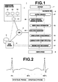
- FIG. 1 illustrates the schematic structure of a hospital system 1 that includes a diagnosis assisting apparatus according to an embodiment of the present invention.
- the hospital system 1 is constituted by: an examination room system 3; a data server 4; and a diagnosis workstation 6 (WS 6); which are connected to each other via a local area network 2 (LAN 2).
- LAN 2 local area network
- the examination room system 3 is constituted by: various modalities 32 for imaging subjects; and an examination room workstation 31 (WS 31) for confirming and adjusting images output from each modality.
- the modalities 32 include: an X ray imaging apparatus; an MSCT (Multi Slice Computed Tomography) apparatus; a DSCT (Dual Source Computed Tomography) apparatus; an MRI (Magnetic Resonance Imaging) apparatus, and a PET (Positron Emission Tomography) apparatus.
- the modalities 32 are apparatuses that comply with DICOM (Digital Imaging and Communication in Medicine) standards that appends data to the obtained sets of volume data and outputs them as DICOM files.
- DICOM Digital Imaging and Communication in Medicine
- the files output by the modalities 32 are forwarded to the data server 4 by the examination room WS 31.
- the data server 4 is a comparatively high processing performance computer equipped with a high performance processor and a high capacity memory, in which a software program that provides the functions of a DBMS (Database Management Server) is installed.
- the software program is stored in the memory, and executed by the processor.
- the data server 4 causes the volume data sent from the examination room WS 31 to be stored in a high capacity storage 5.
- the data server selects files that satisfy search conditions from among the plurality of files stored in the high capacity storage 5, in response to search requests from the diagnosis WS 6. Then, the data server 4 sends the selected files to the diagnosis WS 6.
- the diagnosis WS 6 is a general purpose workstation equipped with a normal processor, memory and storage, in which a diagnosis assisting program is loaded.
- the diagnosis assisting program is installed in the diagnosis WS 6 from a recording medium such as a DVD, or by being downloaded from a server computer on a network.
- a display 7, and input devices 8 such as a keyboard and a mouse are connected to the diagnosis WS 6.
- the diagnosis assisting program installed in the diagnosis WS 6 is constituted by a group of programmodules that realize various functions.
- the program modules is a group of program modules that realizes coronary artery analyzing functions. These programs are recorded in the storage, loaded into the memory when booted up, and executed by the processor.
- the diagnosis WS 6 operates as various processing means that include a volume data obtaining means 61, a coronary artery region extracting means 62, a correlation establishing means 63, an index value calculating means 64, an index value integrating means 65, an alert required region detecting means 66, and an output control means 67 illustrated in Figure 1 .
- Imaging synchronized with ECG's employing an MSCT apparatus or a DSCT apparatus is performed for examinations of the heart.
- 10 to 20 sets of volume data are obtained within a single cardiac cycle, and output as files.
- FIG. 2 The upper portion of Figure 2 represents the waveform of an ECG.
- the period between a first R wave and a next R wave corresponds to a single cardiac cycle.
- Positions along the horizontal axis (temporal axis) of the ECG are phases, which are represented as percentages by dividing the single cardiac cycle into 100. For example, if 10 sets of volume data are obtained during the single cardiac cycle at equal intervals, the phases represented by each set of volume data are: R-R0%, R-R10%, R-R20%, R-R30%, ... R-R90%. Note that although there are differences in heartbeats among individuals, in many cases, the systolic phase is from R-R0% to about R-R45%, and the diastolic phase is from about R-R45% to R-R100%.
- Figures 3A through 3J are diagrams that illustrate examples of sets of volume data obtained by imaging synchronized with an ECG. More specifically, Figures 3A through 3J are examples of volume rendered images (hereinafter, referred to as "VR images") which are generated from volume data.
- VR images volume rendered images
- Figure 3A illustrates a heart at R-R0%
- Figure 3B illustrates a heart at R-R10%
- Figure 3C illustrates a heart at R-R20%
- Figure 3D illustrates a heart at R-R30%
- Figure 3E illustrates a heart at R-R40%
- Figure 3F illustrates a heart at R-R50%
- Figure 3G illustrates a heart at R-R60%
- Figure 3H illustrates a heart at R-R70%
- Figure 3I illustrates a heart at R-R80%
- Figure 3J illustrates a heart at R-R90%.
- Figures 3A through 3J represent a heart as viewed from the front of a human body.
- the blood vessel along the wall of the heart toward the left in the drawings is the right coronary artery
- the blood vessel along the wall of the heart toward the right in the drawings is the left coronary artery.
- the volume data obtaining means 61 transmits the input data to the data server 4, to request search and transfer files which are stored in the high capacity storage 5.
- the files for which transfer is requested may be files that represent specific phases.
- the range of phases to be requested may be defined in setting data in advance, or may be specified by a user by providing a predetermined user interface.
- the data server 4 searches the files within the high capacity storage 5 and transfers the requested group of files to the volume data obtaining means 61 in response to the aforementioned request. If specific phases are not specified in the request, the data server 4 transfers all files which are obtained during a single cardiac cycle. On the other hand, if specific phases are specified, the data server 4 transfers only files that represent the specified phases.
- the volume data obtaining means 61 stores the volume data included in the files transferred from the data server 4 into the memory.
- the coronary artery region extracting means 62 extracts coronary artery regions, that is, the walls and the intravascular regions of the coronary arteries, from each of the sets of volume data stored in the memory by the above process.
- the paths fo the coronary arteries are specified during the process for extracting the coronary artery regions.
- These processes may be performed with respect to all of the supplied volume data. Alternatively, these processes may be performed only with respect to sets of volume data that represent specific phases.
- the targets of these processes (the range of phases to be processed) may be defined in advance in setting data, or may be specified by a user by providing a predetermined user interface.
- the number of sets of data to be processed it is preferable for the number of sets of data to be processed to be reduced, by the processing targets being narrowed by the volume data obtaining means 61 or by coronary artery region extracting means 62 as described above.
- the number of sets of data may be reduced by thinning 20 sets of data are obtained at phase intervals of 5% by selecting 10 sets of volume data at phase intervals of 10%, for example.
- sets of volume data which are effective for analysis such as those obtained during a telesystolic phase and a middiastolic phase may be selected, while sets of volume data that represent other phases are excluded.
- the coronary artery region extracting means 62 extracts a region corresponding to the heart (hereinafter, referred to as a "cardiac region") from volume data based on a predetermined algorithm.
- Figure 4 is a diagram that illustrates an example of a cardiac region 9 extracted by the coronary artery region extracting means 62.
- Positions Sref of points that characterize the shape of the heart, such as the position of the aortic valve, the position of the mitral valve, and the position of the apex of the heart, are also specified during the process for extracting the cardiac region 9.
- the coordinates of the specified positions are stored in the memory, and utilized to define a reference coordinate system in processes to be described later.
- a rectangular parallelepiped region that includes the cardiac region 9 is set as a search range, linear structures are searched for within the search range based on a predetermined algorithm. Further, points which are estimated to be points along the cores of coronary arteries are detected, based on the linear structures detected by the search. In the following description, the points which are estimated to be points along the cores of coronary arteries will be referred to as candidate points or nodes.
- Figure 5 illustrates an example of a linear structure 10 and detected candidate points Ni.
- the search for the linear structures is performed by calculating eigenvalues of a 3x3 Hessian matrix for each local region within the search range.
- regions that include linear structures one of the three eigenvalues of the Hessian matrix becomes a value close to zero, while the other two values will be relatively greater values.
- the eigenvector that corresponds to the eigenvalue close to zero indicates the direction of the main axis of the linear structures.
- the coronary artery region extracting means 62 utilizes this relationship to judge likelihoods of being linear structures based on the eigenvalues of a Hessian matrix for each local region. In local regions in which linear structures are discriminated, the center points thereof are detected as candidate points.
- the resolution of the data within the search range is converted to generate a plurality of sets of data having different resolutions (a Gaussian pyramid), and to repeatedly perform searches (scans) at different resolutions.
- a Gaussian pyramid a Gaussian pyramid
- scans searches
- the candidate points which are detected by the search are linked based on a predetermined algorithm.
- tree structures constituted by the candidate points and blood vessel branches (edges) that connect the candidate points are constructed, as illustrated in Figure 6 .
- the coordinate data of the detected plurality of candidate points and vector data that represent the directions of the blood vessel branches are stored in the memory, along with identifiers for the candidate points and the blood vessel branches.
- the shapes of the coronary arteries are discriminated in detail based on the values of the surrounding voxels (CT values) for each detected candidate point. More specifically, the outlines (the outer walls of the blood vessels) of the coronary arteries are discriminated within cross sections perpendicular to the pathways of the coronary arteries. The discrimination of shapes is performed employing a known segmentation method, such as the Graph Cuts method.
- the coronary artery region extracting means 62 defines a reference coordinate system, in which the positions Sref of the aortic valve, the mitral valve, and the apex of the heart which were stored in the process for discriminating the cardiac region 9 are designated as reference positions.
- the apex of the heart is set as the origin of the reference coordinate system
- the direction from the apex of the heart toward the aortic valve is designated as a Z axis
- the X and Y axes are defined based on the relationship with the mitral valve, as illustrated in Figure 7 .
- the scale of the coordinate system is normalized by defining the distance from the apex of the heart to the aortic valve as 1.
- the coordinate values which were recorded in the memory by the aforementioned processes are converted to coordinate values within the reference coordinate system. That is, data that represent the positions of the candidate points and the branches, the outlines of the coronary arteries, and the like are normalized.
- the normalized data are correlated with data prior to normalization, and stored in the memory.
- the normalized data regarding the candidate points and the outlines will be referred to as coronary artery region data in the following description.
- the processes which are performed by the correlation establishing means 63 will be described.
- the processes which are performed by the coronary artery region extracting means 63 are performed with respect to a plurality of sets of volume data which are obtained during different phases. Accordingly, a plurality of sets of coronary artery region data are obtained for coronary arteries for a single heart.
- Figure 8 is a diagram in which the main portions of the coronary artery regions in Figure 3D (R-R30%) and Figure 3H (R-R70%) are overlapped on each other. As illustrated in Figure 8 , the paths of the coronary arteries differ during the systolic phase and the diastolic phase.
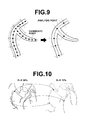
- the correlation establishing means 63 establishes correlations among the plurality of sets of coronary artery region data obtained with respect to the coronary arteries of a single heart. More specifically, correlations are established among candidate points which have different positional coordinates within the reference coordinate systembut are positioned at the same anatomical points. Correlations may be established among all of the candidate points that constitute the tree structures. However, in the present embodiment, a portion of the candidate points are set as analysis points as illustrated in Figure 9 , and correlations are established only among the set analysis points. The analysis points are set by the following process.
- the correlation establishing means 63 divides the tree structures which are specified by the candidate points and the branches into segments.
- candidate points which are linked to three or more branches that is, candidate points which are positioned at branching points, are set as the boundaries of the segments.
- candidate points and branches that extend beyond the branching points are divided into segments having a predetermined number of candidate points or segments having a predetermined length. Then, the candidate points which are positioned at the boundaries of each segment are selected as the analysis points.
- the analysis points are set by the correlation establishing means 63 storing data necessary to specify the analysis points (the positional coordinates or identifiers of the candidate points).
- the correlation establishing means 63 establishes correlations among analysis points which are estimated to be at the same anatomical points by a graph matching technique.
- the correlation establishing means 63 calculates degrees of similarity among analysis points which are set along the paths of coronary arteries based on a predetermined evaluating function, and establishes correlations among analysis points having the highest degrees of similarity.
- the evaluating function is defined, taking the positional coordinates within the reference coordinate system, the numbers and coordinate values of the candidate points which are linked to the analysis points, the diameters of the blood vessels in the periphery of the analysis points, etc., into consideration.
- analysis points which are positioned at the same anatomical points can be correlated with each other even if the shapes and the positions of coronary arteries differ during the systolic phase and the diastolic phase, as illustrated in Figure 10 .
- the index value calculating means 64 calculates an index value that indicates the character of plaque at each analysis point within each of the plurality of coronary artery regions extracted by the coronary artery region extracting means 62.
- Figure 11A and Figure 11B are diagrams that illustrate cross sections of coronary arteries at analysis points, wherein Figure 11A illustrates a normal coronary artery, and Figure 11B illustrates a coronary artery having plaque deposits on the inner walls thereof.
- the index value calculating means 61 discriminates an intravascular region 12 and a plaque region 13 within a coronary artery region 11.
- the CT values of soft plaque are lower than the CT values of a normal intravascular region, and the CT values of hard plaque are higher than the CT values of a normal intravascular region.
- the index value calculating means 64 utilizes this relationship among signal values to distinguish plaque regions and intravascular regions. More specifically, the value of each voxel that constitutes cross sections is compared against predetermined threshold values, to judge whether the voxels represent plaque or intravascular regions.
- plaque region 13 A region constituted by voxels which have been judged to represent plaque is designated as the plaque region 13, and a region constituted by voxels which have been judged to represent an intravascular region is designated as the intravascular region 12. Note that plaque is also classified into soft plaque and hard plaque.
- the threshold values which are employed to distinguish plaque regions and intravascular regions are set as two borderlines B1 and B2 that divide the plane of a coordinate having signal values as the horizontal axis and the diameters of blood vessels (average diameters or average radii measured in a plurality of directions) as the horizontal axis into three sections.
- These borderlines are set by performing learning in advance, using sample data that represent normal blood vessels and blood vessels with plaque deposits having different thicknesses.
- the set borderlines are stored in the memory, and referred to by the index value calculating means 64.
- the index value calculating means 64 judges whether voxels represent soft plaque, hard plaque, or an intravascular region, based on which sides of the borderlines B1 and B2 coordinate points (signal values of the voxels and the diameter of blood vessels) on the coordinate plane of Figure 12 are positioned.
- the thicknesses of blood vessels are in a correlative relationship not only with the diameters of blood vessels, but also with the areas thereof. Therefore, the vertical axis of the coordinate plane for setting the borderlines may alternatively be the areas of blood vessels.
- a first index value I1 is the percentage of the coronary artery region that plaque occupies, that is, the stenosis rate.
- the first index value I1 is calculated by Formula (1) below.
- Aplaque is the area of the plaque region 13
- Aall is the area of the coronary artery region 11.
- Aall may be a combined area of the plaque region 13 and the intravascular region 12. Note that the area of each of the regions can be derived based on the number of voxels that constitute the region.
- I ⁇ 1 Aplaque / Aall ⁇ 100
- a second index value I2 is a value that represents the likelihood that plaque is unstable. Among plaque which adheres to the walls of blood vessels, soft plaque is more unstable compared to hard plaque. Therefore, it is said that the risk of thrombosis occurring due to plaque breakdown is more likely to occur with soft plaque compared to hard plaque.
- the index value 12 becomes high in cases that the signal values of plaque regions are low (soft plaque) and becomes low in cases that the signal values of plaque regions are high (hard plaque).
- a value of 1 is output as the index value I2 if the average signal value of a plaque region is positioned toward the left of the borderline B1; a value of 0.5 is output as the index value I2 if the average signal value of a plaque region is positioned toward the right of the borderline B2; and a value of 0 is output if no plaque regions are present.
- the index value calculating means 64 may output a value obtained by multiplying the index value I1 by the index value I2 as a third index value I3.
- the index values which are calculated by the index value calculating means 64 are not limited to the examples described above.
- Other examples of index values include index values that indicate judgment results regarding whether plaque is present, index values that indicate characteristics other than instability (for example, hardness), and index values that indicate the components of plaque.
- the index values are calculated based on the diameters or the areas of coronary artery regions and the signal values of voxels. However, there are index values that can be calculated based only on the diameters, only on the areas, and only on the signal values.
- Ratios between the diameters or the areas of coronary artery regions and intravascular regions may be calculated as index values that indicate the degree of stenosis, for example.
- whether plaque is present may be judged based only on signal values, and the judgment results may be output as index values.
- index values I1 and I2 are obtained for each of the analysis points for which correlations have been established by the correlation establishingmeans.
- the coronary artery region extracting means 62 executes the coronary artery region extracting process for six phases
- 6n values are calculated for each type of index value, as illustrated in Table 1.
- Table 1 illustrates calculation results for index value I1, 6n values are also obtained for index value I2.
- the plurality of analysis points which are set along the paths fo coronary arteries in phases R-Rx% (0 ⁇ x ⁇ 100, x represents a phase) and correlated with each other are expressed as apxi (0 ⁇ i ⁇ n, i represents an identifier of each analysis point, and n represents the number of analysis points).
- points which are correlated and recognized as being points at the same anatomical position are expressed as APi.
- the index value calculating means 64 performs the index value calculating processes with respect to the analysis points apxi, which are set within each of the coronary artery regions. For this reason, the index value calculating means 64 calculates a plurality of index values for points (cross sections) which are positioned at the same anatomical points.
- the index value integrating means 65 derives a single integrated evaluation value for each analysis point APi, by integrating the plurality of index values which are output by the index value calculating means 64.
- the index value integrating means 65 calculates weighted averages of the plurality of index values I1 and I2 by obtaining weighted averages of the index values which have been calculated for each phase, and outputs the weighted averages as evaluation values.
- evaluation values which are derived from the index values I1 will be expressed as VI
- evaluation values which are derived from the index values 12 will be expressed as V2.
- Evaluation values V1APi for the points APi can be calculated by Formula (2) below.
- V ⁇ 1 APi ⁇ x ⁇ x ⁇ I ⁇ 1 xi
- ⁇ x is a weighting coefficient set for a phase R-Rx%
- I1 xi (0 ⁇ i ⁇ n) is each of the index values I1 calculated for analysis points apxi along the path of the coronary arteries in the phase R-Rx%.
- Values of the weighting coefficients ⁇ x for all possible phases are registered in the memory in advance. In the present embodiment, combinations of a plurality of weighting coefficients are registered, and the weighting coefficients can be switched by a user performing a selecting operation.
- Table 2 illustrates an example of settings of weighting coefficients ⁇ X . Note that the numerical values shown in Table 2 are merely examples.
- setting example S1 sets the weighting of phases other than the telesystolic phase and the middiastolic phase to 0, and places high weighting coefficients with respect to phases R-R40% and R-R70%.
- the index values calculated for phases in which the influence of motion artifacts, etc. are less likely to occur are heavily weighted, while the index values calculated for the other phases are lightly weighted. Thereby, the reliability of the calculated evaluation values can be improved.
- setting example S2A enables obtainment of evaluation values only from index values calculated for the telesystolic phase (R-R70% and the vicinity thereof), while setting example S2B enables obtainment of evaluation values only from index values calculated for the middiastolic phase (R-R40% and the vicinity thereof) .
- the index values which are calculated for analysis points set within the left coronary artery region may be multiplied by the weighting coefficients of setting example S2A, and the index values which are calculated for analysis points set within the right coronary artery region may be multiplied by the weighting coefficients of setting example S2B.
- the reliability of the calculated evaluation values can be further improved.
- the alert required region detecting means 66 detects regions at which alerts are required, based on the evaluation values V1APi and V2APi calculated by the index value integrating means 65. In the present embodiment, if at least one of the evaluation values V1APi and V2APi calculated for an analysis point APi is greater than threshold values stored in a memory, the analysis point APi is detected as an alert required region. That is, regions at which the stenosis rate is high are judged as alert required regions even if plaque is stable, and regions at which the instability of plaque is high are judged as alert required regions even if the stenosis rate is low. It goes without saying that regions having both high stenosis rates and high instability of plaque are judges as alert required regions. Note that it is preferable for the threshold values to be employed to detect the alert required regions to be determined based on past cases. In addition, the definitions of and the detecting methods for the alert required regions may be appropriately determined according to diagnosis principles, and are not limited to those described above.
- FIG. 13 is a diagram that illustrates an example of an output display screen.
- an image of the coronary artery region which is color coded according to the evaluation values regarding the character of plaque, is generated and displayed on the screen.
- the image of the coronary artery region to be displayed may be a volume rendered image or a CPR image.
- a highlighting color such as red is assigned to a region which is judged to be an alert required region, and an arrow 14 that points to the alert required region is also displayed.
- the manner in which the evaluation results and the alert required regions are indicated is not limited to the example illustrated in Figure 13 , and it goes without saying that various modifications are possible.
- the output control means 67 may output an image of the display screen, a list of numerical values that indicates the correlations among identifiers of the analysis points and the evaluation values, etc. to a printer or to a recording medium, in addition to outputting the display screen to the display 7.
- a conventional method in the case that the phase R-R50% is selected, the character of plaque cannot be evaluated correctly.
- the present embodiment evaluates the character of plaque based on a plurality of index values which are calculated for a plurality of phases. Therefore, even if a portion of the index values are erroneous, correct evaluation results can be obtained as a whole.
- a conventional method requires physicians to select a set of volume data to be utilized for analysis while observing VR images such as those illustrated in Figures 3A through 3H . However, it is not necessary to select a single set of data in the method of the present embodiment, and no burden is placed on physicians.
- the alert required region detecting means 66 specifies alert required regions in order to lessen the burden placed on physicians during diagnosis.
- the diagnosis WS 6 may simply display the evaluation results regarding the character of plaque, and leave specification of alert required regions to a physician's judgment. That is, an embodiment may be considered in which the diagnosis WS 6 is not equipped with the alert required region detecting means 66.
- the character of plaque is evaluated by calculating the weighted averages of the index values in the embodiment described above.
- embodiments may be considered in which the character of plaque is evaluated by other evaluating methods, such as calculating simple averages and sums of the plurality of index values.
- the number of sets of volume data which are obtained, the method for selecting sets of volume data prior to extracting the coronary artery regions, the weighting coefficients, etc. may be changed as appropriate according to the specifications of the modality, the examination method, and the symptoms of subjects.
- the all of the series of processes from the obtainment of the sets of volume data to output control is performed by the diagnosis WS 6 in the embodiment described above.
- the series of processes may be divided among and executed by a plurality of computers.
Landscapes
- Engineering & Computer Science (AREA)
- Health & Medical Sciences (AREA)
- Life Sciences & Earth Sciences (AREA)
- Medical Informatics (AREA)
- General Health & Medical Sciences (AREA)
- Physics & Mathematics (AREA)
- Nuclear Medicine, Radiotherapy & Molecular Imaging (AREA)
- Radiology & Medical Imaging (AREA)
- Computer Vision & Pattern Recognition (AREA)
- Public Health (AREA)
- Veterinary Medicine (AREA)
- Animal Behavior & Ethology (AREA)
- Biophysics (AREA)
- Surgery (AREA)
- Molecular Biology (AREA)
- Pathology (AREA)
- Biomedical Technology (AREA)
- Heart & Thoracic Surgery (AREA)
- Optics & Photonics (AREA)
- High Energy & Nuclear Physics (AREA)
- Physiology (AREA)
- General Physics & Mathematics (AREA)
- Quality & Reliability (AREA)
- Theoretical Computer Science (AREA)
- Vascular Medicine (AREA)
- Cardiology (AREA)
- Apparatus For Radiation Diagnosis (AREA)
- Magnetic Resonance Imaging Apparatus (AREA)
- Measuring And Recording Apparatus For Diagnosis (AREA)
Applications Claiming Priority (1)
| Application Number | Priority Date | Filing Date | Title |
|---|---|---|---|
| JP2010050009A JP4981938B2 (ja) | 2010-03-08 | 2010-03-08 | 診断支援装置、冠動脈解析プログラムおよび冠動脈解析方法 |
Publications (3)
| Publication Number | Publication Date |
|---|---|
| EP2365471A2 true EP2365471A2 (de) | 2011-09-14 |
| EP2365471A3 EP2365471A3 (de) | 2013-02-13 |
| EP2365471B1 EP2365471B1 (de) | 2013-11-27 |
Family
ID=44140766
Family Applications (1)
| Application Number | Title | Priority Date | Filing Date |
|---|---|---|---|
| EP20110155534 Not-in-force EP2365471B1 (de) | 2010-03-08 | 2011-02-23 | Diagnosehilfsvorrichtung, Herzarterienanalyseverfahren und Aufzeichnungsmedium mit einem Herzarterienanalyseprogramm darauf |
Country Status (4)
| Country | Link |
|---|---|
| US (1) | US9125622B2 (de) |
| EP (1) | EP2365471B1 (de) |
| JP (1) | JP4981938B2 (de) |
| CN (1) | CN102194049A (de) |
Families Citing this family (23)
| Publication number | Priority date | Publication date | Assignee | Title |
|---|---|---|---|---|
| KR101113747B1 (ko) * | 2011-08-26 | 2012-02-22 | 전남대학교병원 | 마이크로 ct를 이용한 스텐트 내 재협착 평가 방법 |
| JP5395868B2 (ja) * | 2011-09-26 | 2014-01-22 | 富士フイルム株式会社 | 画像処理装置および方法ならびにプログラム |
| JP5797124B2 (ja) * | 2012-01-31 | 2015-10-21 | 富士フイルム株式会社 | 手術支援装置、手術支援方法および手術支援プログラム |
| WO2014084398A1 (ja) | 2012-11-30 | 2014-06-05 | 株式会社 東芝 | 医用画像診断装置 |
| JP6491378B2 (ja) * | 2012-11-30 | 2019-03-27 | キヤノンメディカルシステムズ株式会社 | 表示方法、医用画像診断装置、及びプログラム |
| JP6553147B2 (ja) * | 2012-11-30 | 2019-07-31 | キヤノンメディカルシステムズ株式会社 | 医用画像処理装置及び医用画像処理方法 |
| US20150164451A1 (en) * | 2013-12-18 | 2015-06-18 | Heartflow, Inc. | Systems and methods for predicting coronary plaque vulnerability from patient-specific anatomic image data |
| US9413757B1 (en) | 2015-01-15 | 2016-08-09 | International Business Machines Corporation | Secure identity authentication in an electronic transaction |
| US10478130B2 (en) | 2015-02-13 | 2019-11-19 | Siemens Healthcare Gmbh | Plaque vulnerability assessment in medical imaging |
| JP6671946B2 (ja) * | 2015-12-11 | 2020-03-25 | キヤノン株式会社 | 情報取得装置、撮像装置及び情報取得方法 |
| DE102015225115A1 (de) * | 2015-12-14 | 2017-06-14 | Siemens Healthcare Gmbh | Paralleles Arbeiten an einer medizinischen Röntgeneinrichtung |
| JP7270331B2 (ja) * | 2017-06-15 | 2023-05-10 | キヤノンメディカルシステムズ株式会社 | 医用画像診断装置及び画像処理装置 |
| GB2569332B (en) * | 2017-12-13 | 2021-06-09 | Univ Oxford Innovation Ltd | Method and apparatus for analysing images |
| CN112584738B (zh) * | 2018-08-30 | 2024-04-23 | 奥林巴斯株式会社 | 记录装置、图像观察装置、观察系统、观察系统的控制方法及存储介质 |
| EP3671649B1 (de) * | 2018-12-19 | 2025-07-02 | Siemens Healthineers AG | Verfahren und computersystem zur erzeugung einer kombinierten gewebe-gefäss-darstellung |
| US20220392065A1 (en) | 2020-01-07 | 2022-12-08 | Cleerly, Inc. | Systems, methods, and devices for medical image analysis, diagnosis, risk stratification, decision making and/or disease tracking |
| JP2023509514A (ja) | 2020-01-07 | 2023-03-08 | クリールリー、 インコーポレーテッド | 医用画像分析、診断、重症度分類、意思決定、および/または疾患追跡のためのシステム、方法、およびデバイス |
| US11969280B2 (en) | 2020-01-07 | 2024-04-30 | Cleerly, Inc. | Systems, methods, and devices for medical image analysis, diagnosis, risk stratification, decision making and/or disease tracking |
| JP7443197B2 (ja) * | 2020-08-25 | 2024-03-05 | キヤノンメディカルシステムズ株式会社 | 医用画像処理装置、システム及び方法 |
| US12440180B2 (en) | 2022-03-10 | 2025-10-14 | Cleerly, Inc. | Systems, devices, and methods for non-invasive image-based plaque analysis and risk determination |
| US12406365B2 (en) * | 2022-03-10 | 2025-09-02 | Cleerly, Inc. | Systems, devices, and methods for non-invasive image-based plaque analysis and risk determination |
| US20250143657A1 (en) | 2022-03-10 | 2025-05-08 | Cleerly, Inc. | Systems, devices, and methods for non-invasive image-based plaque analysis and risk determination |
| US20250217981A1 (en) | 2022-03-10 | 2025-07-03 | Cleerly, Inc. | Systems, methods, and devices for image-based plaque analysis and risk determination |
Citations (4)
| Publication number | Priority date | Publication date | Assignee | Title |
|---|---|---|---|---|
| JP2009048679A (ja) | 2007-08-15 | 2009-03-05 | Sony Corp | 記憶装置の駆動方法 |
| JP2009069895A (ja) | 2007-09-10 | 2009-04-02 | Fuji Xerox Co Ltd | 文書管理システム |
| JP2009195561A (ja) | 2008-02-22 | 2009-09-03 | Toshiba Corp | X線ct装置、画像処理装置および画像処理プログラム |
| US7646903B2 (en) | 2005-06-22 | 2010-01-12 | Siemens Medical Solutions Usa, Inc. | System and method for path based tree matching |
Family Cites Families (13)
| Publication number | Priority date | Publication date | Assignee | Title |
|---|---|---|---|---|
| US6243437B1 (en) * | 1998-11-25 | 2001-06-05 | General Electric Company | Coronary calcification detection using retrospective cardiac gating of imaging system |
| US6233304B1 (en) * | 1998-11-25 | 2001-05-15 | General Electric Company | Methods and apparatus for calcification scoring |
| US6990222B2 (en) * | 2001-11-21 | 2006-01-24 | Arnold Ben A | Calibration of tissue densities in computerized tomography |
| US7558611B2 (en) * | 2001-11-24 | 2009-07-07 | Image Analysis, Inc. | Automatic detection and quantification of coronary and aortic calcium |
| JP4263943B2 (ja) * | 2003-05-07 | 2009-05-13 | テルモ株式会社 | 超音波診断装置 |
| US7346203B2 (en) * | 2003-11-19 | 2008-03-18 | General Electric Company | Methods and apparatus for processing image data to aid in detecting disease |
| JP4634179B2 (ja) * | 2005-02-15 | 2011-02-16 | 株式会社日立メディコ | 画像診断装置 |
| US7957574B2 (en) * | 2006-11-22 | 2011-06-07 | General Electric Company | Methods and apparatus for generating a risk metric for soft plaque in vessels |
| US20080242977A1 (en) * | 2007-03-30 | 2008-10-02 | General Electric Company | Systems, methods and apparatus for longitudinal/temporal analysis of plaque lesions |
| JP5208442B2 (ja) * | 2007-04-12 | 2013-06-12 | ジーイー・メディカル・システムズ・グローバル・テクノロジー・カンパニー・エルエルシー | X線ct装置 |
| US7957570B2 (en) * | 2007-05-03 | 2011-06-07 | General Electric Company | System and method to generate an illustration of a cardiac region of interest |
| JP2009136573A (ja) * | 2007-12-07 | 2009-06-25 | Konica Minolta Medical & Graphic Inc | 動態撮影システム |
| JP5491729B2 (ja) * | 2008-12-12 | 2014-05-14 | 株式会社東芝 | 画像処理装置及び狭窄状態解析プログラム |
-
2010
- 2010-03-08 JP JP2010050009A patent/JP4981938B2/ja active Active
-
2011
- 2011-02-23 EP EP20110155534 patent/EP2365471B1/de not_active Not-in-force
- 2011-02-25 US US13/035,471 patent/US9125622B2/en active Active
- 2011-03-07 CN CN2011100555196A patent/CN102194049A/zh active Pending
Patent Citations (4)
| Publication number | Priority date | Publication date | Assignee | Title |
|---|---|---|---|---|
| US7646903B2 (en) | 2005-06-22 | 2010-01-12 | Siemens Medical Solutions Usa, Inc. | System and method for path based tree matching |
| JP2009048679A (ja) | 2007-08-15 | 2009-03-05 | Sony Corp | 記憶装置の駆動方法 |
| JP2009069895A (ja) | 2007-09-10 | 2009-04-02 | Fuji Xerox Co Ltd | 文書管理システム |
| JP2009195561A (ja) | 2008-02-22 | 2009-09-03 | Toshiba Corp | X線ct装置、画像処理装置および画像処理プログラム |
Non-Patent Citations (1)
| Title |
|---|
| A. SZYMCZAK ET AL.: "Coronary Vessel Trees from 3D Imagery: A Topological Approach", MEDICAL IMAGE ANALYSIS, vol. 10, no. 4, 2006, pages 548 - 559, XP028013477, DOI: doi:10.1016/j.media.2006.05.002 |
Also Published As
| Publication number | Publication date |
|---|---|
| CN102194049A (zh) | 2011-09-21 |
| EP2365471A3 (de) | 2013-02-13 |
| US9125622B2 (en) | 2015-09-08 |
| JP4981938B2 (ja) | 2012-07-25 |
| US20110218427A1 (en) | 2011-09-08 |
| JP2011182899A (ja) | 2011-09-22 |
| EP2365471B1 (de) | 2013-11-27 |
Similar Documents
| Publication | Publication Date | Title |
|---|---|---|
| EP2365471B1 (de) | Diagnosehilfsvorrichtung, Herzarterienanalyseverfahren und Aufzeichnungsmedium mit einem Herzarterienanalyseprogramm darauf | |
| US7567696B2 (en) | System and method for detecting the aortic valve using a model-based segmentation technique | |
| US8380013B2 (en) | Case image search apparatus, method and computer-readable recording medium | |
| JP5868231B2 (ja) | 医用画像診断支援装置、医用画像診断支援方法ならびにコンピュータプログラム | |
| US8422752B2 (en) | Diagnosis assisting apparatus, diagnosis assisting method, and storage medium in which a diagnosis assisting program is recorded | |
| US20190099147A1 (en) | Systems and methods for determining hepatic function from liver scans | |
| KR102469907B1 (ko) | 복수의 폐질환을 스크리닝하기 위한 의료 영상 재구성 장치 및 방법 | |
| KR102676569B1 (ko) | 의료 영상 분석 장치 및 방법, 의료 영상 시각화 장치 및 방법 | |
| EP2810598A1 (de) | Chirurgische hilfsvorrichtung, chirurgisches hilfsverfahren und chirurgisches hilfsprogramm | |
| JP7187244B2 (ja) | 医用画像処理装置、医用画像処理システム及び医用画像処理プログラム | |
| JP5700964B2 (ja) | 医用画像処理装置、方法およびプログラム | |
| US8958616B2 (en) | Image processing device and image processing method | |
| CN112861961B (zh) | 肺血管分类方法及装置、存储介质及电子设备 | |
| JP2007530160A (ja) | 医用画像のための自動決定支援を提供するシステムおよび方法 | |
| CN112950648A (zh) | 确定磁共振图像中的正中矢状平面的方法和设备 | |
| US9905002B2 (en) | Method and system for determining the prognosis of a patient suffering from pulmonary embolism | |
| Mamalakis et al. | Artificial Intelligence framework with traditional computer vision and deep learning approaches for optimal automatic segmentation of left ventricle with scar | |
| US12499552B2 (en) | Image processing apparatus, image processing method, and recording medium | |
| Mehta et al. | Heart Disease Diagnosis using Deep Learning | |
| US9808175B1 (en) | Method and system for analyzing images to quantify brain atrophy | |
| Pawar et al. | Deep learning watershed algorithm to calculate cardiac stroke volume of the left ventricle for the analysis to detect person suffering from cardiac vascular diseases using cardiac MRI data | |
| Stetten et al. | Automated segmentation of the right heart using an optimized shells and spheres algorithm | |
| WO2025223980A1 (en) | Method, system and computer program for identification and temporal tracking of equivalent lesions in medical images | |
| WO2025128003A1 (en) | Systems and methods for analysing arterial calcium | |
| EP3944252A1 (de) | System zur automatischen bewertung der anpassung medizinischer vorrichtungen an virtuelle patienten |
Legal Events
| Date | Code | Title | Description |
|---|---|---|---|
| PUAI | Public reference made under article 153(3) epc to a published international application that has entered the european phase |
Free format text: ORIGINAL CODE: 0009012 |
|
| AK | Designated contracting states |
Kind code of ref document: A2 Designated state(s): AL AT BE BG CH CY CZ DE DK EE ES FI FR GB GR HR HU IE IS IT LI LT LU LV MC MK MT NL NO PL PT RO RS SE SI SK SM TR |
|
| AX | Request for extension of the european patent |
Extension state: BA ME |
|
| PUAL | Search report despatched |
Free format text: ORIGINAL CODE: 0009013 |
|
| AK | Designated contracting states |
Kind code of ref document: A3 Designated state(s): AL AT BE BG CH CY CZ DE DK EE ES FI FR GB GR HR HU IE IS IT LI LT LU LV MC MK MT NL NO PL PT RO RS SE SI SK SM TR |
|
| AX | Request for extension of the european patent |
Extension state: BA ME |
|
| RIC1 | Information provided on ipc code assigned before grant |
Ipc: G06T 7/00 20060101AFI20130110BHEP |
|
| 17P | Request for examination filed |
Effective date: 20130410 |
|
| GRAP | Despatch of communication of intention to grant a patent |
Free format text: ORIGINAL CODE: EPIDOSNIGR1 |
|
| INTG | Intention to grant announced |
Effective date: 20130613 |
|
| GRAS | Grant fee paid |
Free format text: ORIGINAL CODE: EPIDOSNIGR3 |
|
| GRAA | (expected) grant |
Free format text: ORIGINAL CODE: 0009210 |
|
| AK | Designated contracting states |
Kind code of ref document: B1 Designated state(s): AL AT BE BG CH CY CZ DE DK EE ES FI FR GB GR HR HU IE IS IT LI LT LU LV MC MK MT NL NO PL PT RO RS SE SI SK SM TR |
|
| REG | Reference to a national code |
Ref country code: GB Ref legal event code: FG4D |
|
| REG | Reference to a national code |
Ref country code: CH Ref legal event code: EP |
|
| REG | Reference to a national code |
Ref country code: AT Ref legal event code: REF Ref document number: 642978 Country of ref document: AT Kind code of ref document: T Effective date: 20131215 |
|
| REG | Reference to a national code |
Ref country code: IE Ref legal event code: FG4D |
|
| REG | Reference to a national code |
Ref country code: DE Ref legal event code: R096 Ref document number: 602011003914 Country of ref document: DE Effective date: 20140123 |
|
| REG | Reference to a national code |
Ref country code: NL Ref legal event code: T3 |
|
| REG | Reference to a national code |
Ref country code: AT Ref legal event code: MK05 Ref document number: 642978 Country of ref document: AT Kind code of ref document: T Effective date: 20131127 |
|
| REG | Reference to a national code |
Ref country code: LT Ref legal event code: MG4D |
|
| PG25 | Lapsed in a contracting state [announced via postgrant information from national office to epo] |
Ref country code: FI Free format text: LAPSE BECAUSE OF FAILURE TO SUBMIT A TRANSLATION OF THE DESCRIPTION OR TO PAY THE FEE WITHIN THE PRESCRIBED TIME-LIMIT Effective date: 20131127 Ref country code: SE Free format text: LAPSE BECAUSE OF FAILURE TO SUBMIT A TRANSLATION OF THE DESCRIPTION OR TO PAY THE FEE WITHIN THE PRESCRIBED TIME-LIMIT Effective date: 20131127 Ref country code: HR Free format text: LAPSE BECAUSE OF FAILURE TO SUBMIT A TRANSLATION OF THE DESCRIPTION OR TO PAY THE FEE WITHIN THE PRESCRIBED TIME-LIMIT Effective date: 20131127 Ref country code: IS Free format text: LAPSE BECAUSE OF FAILURE TO SUBMIT A TRANSLATION OF THE DESCRIPTION OR TO PAY THE FEE WITHIN THE PRESCRIBED TIME-LIMIT Effective date: 20140327 Ref country code: LT Free format text: LAPSE BECAUSE OF FAILURE TO SUBMIT A TRANSLATION OF THE DESCRIPTION OR TO PAY THE FEE WITHIN THE PRESCRIBED TIME-LIMIT Effective date: 20131127 Ref country code: NO Free format text: LAPSE BECAUSE OF FAILURE TO SUBMIT A TRANSLATION OF THE DESCRIPTION OR TO PAY THE FEE WITHIN THE PRESCRIBED TIME-LIMIT Effective date: 20140227 |
|
| PG25 | Lapsed in a contracting state [announced via postgrant information from national office to epo] |
Ref country code: BE Free format text: LAPSE BECAUSE OF FAILURE TO SUBMIT A TRANSLATION OF THE DESCRIPTION OR TO PAY THE FEE WITHIN THE PRESCRIBED TIME-LIMIT Effective date: 20131127 Ref country code: RS Free format text: LAPSE BECAUSE OF FAILURE TO SUBMIT A TRANSLATION OF THE DESCRIPTION OR TO PAY THE FEE WITHIN THE PRESCRIBED TIME-LIMIT Effective date: 20131127 Ref country code: AT Free format text: LAPSE BECAUSE OF FAILURE TO SUBMIT A TRANSLATION OF THE DESCRIPTION OR TO PAY THE FEE WITHIN THE PRESCRIBED TIME-LIMIT Effective date: 20131127 Ref country code: LV Free format text: LAPSE BECAUSE OF FAILURE TO SUBMIT A TRANSLATION OF THE DESCRIPTION OR TO PAY THE FEE WITHIN THE PRESCRIBED TIME-LIMIT Effective date: 20131127 Ref country code: ES Free format text: LAPSE BECAUSE OF FAILURE TO SUBMIT A TRANSLATION OF THE DESCRIPTION OR TO PAY THE FEE WITHIN THE PRESCRIBED TIME-LIMIT Effective date: 20131127 Ref country code: CY Free format text: LAPSE BECAUSE OF FAILURE TO SUBMIT A TRANSLATION OF THE DESCRIPTION OR TO PAY THE FEE WITHIN THE PRESCRIBED TIME-LIMIT Effective date: 20131127 |
|
| PG25 | Lapsed in a contracting state [announced via postgrant information from national office to epo] |
Ref country code: PT Free format text: LAPSE BECAUSE OF FAILURE TO SUBMIT A TRANSLATION OF THE DESCRIPTION OR TO PAY THE FEE WITHIN THE PRESCRIBED TIME-LIMIT Effective date: 20140327 |
|
| PG25 | Lapsed in a contracting state [announced via postgrant information from national office to epo] |
Ref country code: EE Free format text: LAPSE BECAUSE OF FAILURE TO SUBMIT A TRANSLATION OF THE DESCRIPTION OR TO PAY THE FEE WITHIN THE PRESCRIBED TIME-LIMIT Effective date: 20131127 |
|
| REG | Reference to a national code |
Ref country code: DE Ref legal event code: R097 Ref document number: 602011003914 Country of ref document: DE |
|
| PG25 | Lapsed in a contracting state [announced via postgrant information from national office to epo] |
Ref country code: SK Free format text: LAPSE BECAUSE OF FAILURE TO SUBMIT A TRANSLATION OF THE DESCRIPTION OR TO PAY THE FEE WITHIN THE PRESCRIBED TIME-LIMIT Effective date: 20131127 Ref country code: CZ Free format text: LAPSE BECAUSE OF FAILURE TO SUBMIT A TRANSLATION OF THE DESCRIPTION OR TO PAY THE FEE WITHIN THE PRESCRIBED TIME-LIMIT Effective date: 20131127 Ref country code: RO Free format text: LAPSE BECAUSE OF FAILURE TO SUBMIT A TRANSLATION OF THE DESCRIPTION OR TO PAY THE FEE WITHIN THE PRESCRIBED TIME-LIMIT Effective date: 20131127 Ref country code: PL Free format text: LAPSE BECAUSE OF FAILURE TO SUBMIT A TRANSLATION OF THE DESCRIPTION OR TO PAY THE FEE WITHIN THE PRESCRIBED TIME-LIMIT Effective date: 20131127 |
|
| PG25 | Lapsed in a contracting state [announced via postgrant information from national office to epo] |
Ref country code: MC Free format text: LAPSE BECAUSE OF FAILURE TO SUBMIT A TRANSLATION OF THE DESCRIPTION OR TO PAY THE FEE WITHIN THE PRESCRIBED TIME-LIMIT Effective date: 20131127 Ref country code: DK Free format text: LAPSE BECAUSE OF FAILURE TO SUBMIT A TRANSLATION OF THE DESCRIPTION OR TO PAY THE FEE WITHIN THE PRESCRIBED TIME-LIMIT Effective date: 20131127 Ref country code: LU Free format text: LAPSE BECAUSE OF FAILURE TO SUBMIT A TRANSLATION OF THE DESCRIPTION OR TO PAY THE FEE WITHIN THE PRESCRIBED TIME-LIMIT Effective date: 20140223 |
|
| REG | Reference to a national code |
Ref country code: CH Ref legal event code: PL |
|
| PLBE | No opposition filed within time limit |
Free format text: ORIGINAL CODE: 0009261 |
|
| STAA | Information on the status of an ep patent application or granted ep patent |
Free format text: STATUS: NO OPPOSITION FILED WITHIN TIME LIMIT |
|
| PG25 | Lapsed in a contracting state [announced via postgrant information from national office to epo] |
Ref country code: CH Free format text: LAPSE BECAUSE OF NON-PAYMENT OF DUE FEES Effective date: 20140228 Ref country code: LI Free format text: LAPSE BECAUSE OF NON-PAYMENT OF DUE FEES Effective date: 20140228 |
|
| 26N | No opposition filed |
Effective date: 20140828 |
|
| REG | Reference to a national code |
Ref country code: IE Ref legal event code: MM4A |
|
| REG | Reference to a national code |
Ref country code: DE Ref legal event code: R097 Ref document number: 602011003914 Country of ref document: DE Effective date: 20140828 |
|
| PG25 | Lapsed in a contracting state [announced via postgrant information from national office to epo] |
Ref country code: IE Free format text: LAPSE BECAUSE OF NON-PAYMENT OF DUE FEES Effective date: 20140223 |
|
| REG | Reference to a national code |
Ref country code: FR Ref legal event code: PLFP Year of fee payment: 5 |
|
| PG25 | Lapsed in a contracting state [announced via postgrant information from national office to epo] |
Ref country code: SI Free format text: LAPSE BECAUSE OF FAILURE TO SUBMIT A TRANSLATION OF THE DESCRIPTION OR TO PAY THE FEE WITHIN THE PRESCRIBED TIME-LIMIT Effective date: 20131127 |
|
| PGFP | Annual fee paid to national office [announced via postgrant information from national office to epo] |
Ref country code: NL Payment date: 20150110 Year of fee payment: 5 |
|
| PGFP | Annual fee paid to national office [announced via postgrant information from national office to epo] |
Ref country code: IT Payment date: 20150209 Year of fee payment: 5 |
|
| PGFP | Annual fee paid to national office [announced via postgrant information from national office to epo] |
Ref country code: FR Payment date: 20150210 Year of fee payment: 5 |
|
| GBPC | Gb: european patent ceased through non-payment of renewal fee |
Effective date: 20150223 |
|
| PG25 | Lapsed in a contracting state [announced via postgrant information from national office to epo] |
Ref country code: GB Free format text: LAPSE BECAUSE OF NON-PAYMENT OF DUE FEES Effective date: 20150223 |
|
| PG25 | Lapsed in a contracting state [announced via postgrant information from national office to epo] |
Ref country code: MT Free format text: LAPSE BECAUSE OF FAILURE TO SUBMIT A TRANSLATION OF THE DESCRIPTION OR TO PAY THE FEE WITHIN THE PRESCRIBED TIME-LIMIT Effective date: 20131127 |
|
| PG25 | Lapsed in a contracting state [announced via postgrant information from national office to epo] |
Ref country code: SM Free format text: LAPSE BECAUSE OF FAILURE TO SUBMIT A TRANSLATION OF THE DESCRIPTION OR TO PAY THE FEE WITHIN THE PRESCRIBED TIME-LIMIT Effective date: 20131127 |
|
| PG25 | Lapsed in a contracting state [announced via postgrant information from national office to epo] |
Ref country code: GR Free format text: LAPSE BECAUSE OF FAILURE TO SUBMIT A TRANSLATION OF THE DESCRIPTION OR TO PAY THE FEE WITHIN THE PRESCRIBED TIME-LIMIT Effective date: 20140228 Ref country code: BG Free format text: LAPSE BECAUSE OF FAILURE TO SUBMIT A TRANSLATION OF THE DESCRIPTION OR TO PAY THE FEE WITHIN THE PRESCRIBED TIME-LIMIT Effective date: 20131127 |
|
| PG25 | Lapsed in a contracting state [announced via postgrant information from national office to epo] |
Ref country code: HU Free format text: LAPSE BECAUSE OF FAILURE TO SUBMIT A TRANSLATION OF THE DESCRIPTION OR TO PAY THE FEE WITHIN THE PRESCRIBED TIME-LIMIT; INVALID AB INITIO Effective date: 20110223 Ref country code: TR Free format text: LAPSE BECAUSE OF FAILURE TO SUBMIT A TRANSLATION OF THE DESCRIPTION OR TO PAY THE FEE WITHIN THE PRESCRIBED TIME-LIMIT Effective date: 20131127 |
|
| REG | Reference to a national code |
Ref country code: NL Ref legal event code: MM Effective date: 20160301 |
|
| REG | Reference to a national code |
Ref country code: FR Ref legal event code: ST Effective date: 20161028 |
|
| PG25 | Lapsed in a contracting state [announced via postgrant information from national office to epo] |
Ref country code: IT Free format text: LAPSE BECAUSE OF NON-PAYMENT OF DUE FEES Effective date: 20160223 |
|
| PG25 | Lapsed in a contracting state [announced via postgrant information from national office to epo] |
Ref country code: FR Free format text: LAPSE BECAUSE OF NON-PAYMENT OF DUE FEES Effective date: 20160229 Ref country code: NL Free format text: LAPSE BECAUSE OF NON-PAYMENT OF DUE FEES Effective date: 20160301 |
|
| REG | Reference to a national code |
Ref country code: DE Ref legal event code: R082 Ref document number: 602011003914 Country of ref document: DE Representative=s name: KLUNKER IP PATENTANWAELTE PARTG MBB, DE |
|
| PG25 | Lapsed in a contracting state [announced via postgrant information from national office to epo] |
Ref country code: MK Free format text: LAPSE BECAUSE OF FAILURE TO SUBMIT A TRANSLATION OF THE DESCRIPTION OR TO PAY THE FEE WITHIN THE PRESCRIBED TIME-LIMIT Effective date: 20131127 |
|
| PG25 | Lapsed in a contracting state [announced via postgrant information from national office to epo] |
Ref country code: AL Free format text: LAPSE BECAUSE OF FAILURE TO SUBMIT A TRANSLATION OF THE DESCRIPTION OR TO PAY THE FEE WITHIN THE PRESCRIBED TIME-LIMIT Effective date: 20131127 |
|
| P01 | Opt-out of the competence of the unified patent court (upc) registered |
Effective date: 20230515 |
|
| PGFP | Annual fee paid to national office [announced via postgrant information from national office to epo] |
Ref country code: DE Payment date: 20231228 Year of fee payment: 14 |
|
| REG | Reference to a national code |
Ref country code: DE Ref legal event code: R119 Ref document number: 602011003914 Country of ref document: DE |
|
| PG25 | Lapsed in a contracting state [announced via postgrant information from national office to epo] |
Ref country code: DE Free format text: LAPSE BECAUSE OF NON-PAYMENT OF DUE FEES Effective date: 20250902 |