EP2365580A1 - Ensemble pour un support d'antenne de toit - Google Patents
Ensemble pour un support d'antenne de toit Download PDFInfo
- Publication number
- EP2365580A1 EP2365580A1 EP10002502A EP10002502A EP2365580A1 EP 2365580 A1 EP2365580 A1 EP 2365580A1 EP 10002502 A EP10002502 A EP 10002502A EP 10002502 A EP10002502 A EP 10002502A EP 2365580 A1 EP2365580 A1 EP 2365580A1
- Authority
- EP
- European Patent Office
- Prior art keywords
- support member
- receiving part
- kit according
- kit
- structural unit
- Prior art date
- Legal status (The legal status is an assumption and is not a legal conclusion. Google has not performed a legal analysis and makes no representation as to the accuracy of the status listed.)
- Withdrawn
Links
- 239000002184 metal Substances 0.000 claims abstract description 3
- 229910052751 metal Inorganic materials 0.000 claims abstract description 3
- 238000006073 displacement reaction Methods 0.000 claims description 5
- 230000000295 complement effect Effects 0.000 claims description 2
- 230000035515 penetration Effects 0.000 description 3
- 238000011161 development Methods 0.000 description 2
- 230000018109 developmental process Effects 0.000 description 2
- 238000004519 manufacturing process Methods 0.000 description 2
- 239000000463 material Substances 0.000 description 2
- XEEYBQQBJWHFJM-UHFFFAOYSA-N Iron Chemical group [Fe] XEEYBQQBJWHFJM-UHFFFAOYSA-N 0.000 description 1
- 230000006978 adaptation Effects 0.000 description 1
- 239000002131 composite material Substances 0.000 description 1
- 238000010276 construction Methods 0.000 description 1
- 238000012937 correction Methods 0.000 description 1
- 230000007797 corrosion Effects 0.000 description 1
- 238000005260 corrosion Methods 0.000 description 1
- 210000004513 dentition Anatomy 0.000 description 1
- 230000001419 dependent effect Effects 0.000 description 1
- 230000000694 effects Effects 0.000 description 1
- 230000002349 favourable effect Effects 0.000 description 1
- 239000004615 ingredient Substances 0.000 description 1
- 238000009434 installation Methods 0.000 description 1
- 230000003993 interaction Effects 0.000 description 1
- 239000007769 metal material Substances 0.000 description 1
- 230000036346 tooth eruption Effects 0.000 description 1
- 238000003466 welding Methods 0.000 description 1
- 239000002023 wood Substances 0.000 description 1
Images


Classifications
-
- H—ELECTRICITY
- H01—ELECTRIC ELEMENTS
- H01Q—ANTENNAS, i.e. RADIO AERIALS
- H01Q1/00—Details of, or arrangements associated with, antennas
- H01Q1/12—Supports; Mounting means
- H01Q1/1207—Supports; Mounting means for fastening a rigid aerial element
- H01Q1/1221—Supports; Mounting means for fastening a rigid aerial element onto a wall
-
- F—MECHANICAL ENGINEERING; LIGHTING; HEATING; WEAPONS; BLASTING
- F16—ENGINEERING ELEMENTS AND UNITS; GENERAL MEASURES FOR PRODUCING AND MAINTAINING EFFECTIVE FUNCTIONING OF MACHINES OR INSTALLATIONS; THERMAL INSULATION IN GENERAL
- F16B—DEVICES FOR FASTENING OR SECURING CONSTRUCTIONAL ELEMENTS OR MACHINE PARTS TOGETHER, e.g. NAILS, BOLTS, CIRCLIPS, CLAMPS, CLIPS OR WEDGES; JOINTS OR JOINTING
- F16B2/00—Friction-grip releasable fastenings
- F16B2/02—Clamps, i.e. with gripping action effected by positive means other than the inherent resistance to deformation of the material of the fastening
- F16B2/06—Clamps, i.e. with gripping action effected by positive means other than the inherent resistance to deformation of the material of the fastening external, i.e. with contracting action
- F16B2/10—Clamps, i.e. with gripping action effected by positive means other than the inherent resistance to deformation of the material of the fastening external, i.e. with contracting action using pivoting jaws
Definitions
- the invention relates to a kit for a roof antenna holder with an attachable to two adjacent rafters support member and a cooperating with the support member receiving part for the lower end of an antenna mast.
- kits Under this genus fall a variety of kits, not least because they can bring depending on the training of their basic components (support member and receiving part) a number of other parts with him to functionally and permanently produce the necessary connection or the necessary connection to other parts.
- the support member on the one hand requires fastening means or parts for securing to the rafters, which are possibly also designed so that corrections (changes in position) are still possible.
- fastening means or parts for securing to the rafters, which are possibly also designed so that corrections (changes in position) are still possible.
- an interaction of support member and receiving part is provided, in which field the materials are subject to the highest stresses, especially in this area. Accordingly complex the individual parts must be formed and carefully selected and set the materials and dimensions accordingly.
- the invention has now taken on the task of proposing a roof antenna holder with the simplest possible components that can be offered as a clear and understandable kit for easy and convenient step-by-step installation.
- support member and receiving part are to form a rigid structural unit.
- this unit should now cooperate with mounting or support parts, which allow for a corresponding relaxation a longitudinal displacement of the unit, as well as a rotation.
- This is e.g. possible with clamps or clamp-like support parts.
- the longitudinal displacement and rotation proposed or required here means that the end areas serving as the supporting part have, on the one hand, a certain projection (beyond the rafter spacing) and, on the other hand, have a cross-sectional shape which permits rotation, under conditions.
- the receiving part off-center on the support member, namely at different distances from the ends arranged.
- the receiving part is welded to the support member.
- the receiving part is a pin, pipe section or cylinder, with which an antenna is connectable to its lower end.
- At least one end region of the assembly which serves as a support member, a longitudinally extending corrugation, knurling or toothing on the outside and has the associated attachment part via a complementary corrugation, knurling or dentition on the inside.
- the assembly is hollow, wherein the support member and the receiving part are closed at their ends.
- the closed ends of the assembly in approximately the shape of spherical caps.
- the components of the kit are made of metal and are galvanized.
- a kit stemmenden - components functionally mounted to a roof antenna holder on two rafters: A from the rafter 1 to the adjacent rafter 1 extending unit 2.
- This has approximately T-shape and includes two. Parts with different functions, namely a linearly oriented support member 3 with free ends or end portions 4, which adjoin a central region 5.
- a receiving part 6 for the lower free end of an antenna mast (not shown) is arranged at right angles to the support member 3, welded thereto. Welding leads here to a rigid connection, which is also insoluble
- the assembly 2 more precisely the support part 3, is held with its end portions 4 of fastening parts.
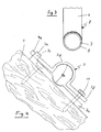
- the latter are designed as clamp-like support parts 7 (see. Fig. 4 ) and bolted to the rafters 1.
- the end regions 4 have on their outside a longitudinally extending corrugation 8 (see also Fig. 3 ).
- the assembly 2 can be both in the direction of the double arrow 9 to move in the longitudinal direction and rotate in the direction of the double arrow 10 about the longitudinal axis of the assembly 2 and the support member 3. This determines the orientation of the antenna and its penetration point through the roof. A permanent fixation is subsequently achieved by bracing the end regions 4 in the support parts 7.
- the Fig. 4 can recognize a support part 7, which can be easily mounted on a rafter 1 and clamped with an end portion 4 of the support member 3.
- the support part 7 consists of a flat support plate 7a with an upwardly directed end piece 7b including a recess 7c.
- the recess 7c engages a clamp 7d with an angled end 7e, so that the clamp 7d is held similar to a joint and can be moved up and down.
- the clamp 7d is tightened at its free end 7f by means of a screw 11 against the support plate 7a.
- the screw 11 is also provided as a fastening screw for the support plate 7a, which is why a wood screw is selected and this penetrates the support plate 7a freely.
- the clamp 7d is pressed against the end region 4 and this against the support plate 7a.
- the support part 7 has at its inner side over a corrugation 8 of the end portions 4 corresponding corrugation 8a, both on the support plate 7a and on the clamp 7d. This results in the assembled state to a substantial or comprehensive positive engagement, which allows neither a longitudinal displacement nor a rotation of the assembly 2 more.
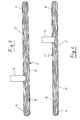
- FIGS. 5 and 6 show still somewhat differently designed units 2a, which are formed of different round tubes, namely a pipe section with corrugated surface (for the support member 3 ') and a right angle thereto arranged pipe section with a smooth surface (for the receiving part 6').
- the receiving part 6 ' is arranged off-center on the support part 3', namely to the left ( Fig. 5 ) or to the right ( Fig. 6 ).
- this may mean that one end portion projects excessively and the other end portion u. U. is no longer completely covered by the support part. This can be done with an embodiment according to FIGS. 5 and 6 be avoided. This is even only a single embodiment, since the assembly according to Fig. 5 by turning 180 ° to the position of Fig. 6 to convict and vice versa.
- a roof antenna holder according to the invention has fundamental advantages over known embodiments. It is thus not only suitable for mounting antennas with larger windage area, such as satellite antennas, but also from other, the wind power exposed roof structures, such as wind turbines, flags o. ⁇ .
Landscapes
- Engineering & Computer Science (AREA)
- General Engineering & Computer Science (AREA)
- Mechanical Engineering (AREA)
- Support Of Aerials (AREA)
Priority Applications (1)
| Application Number | Priority Date | Filing Date | Title |
|---|---|---|---|
| EP10002502A EP2365580A1 (fr) | 2010-03-10 | 2010-03-10 | Ensemble pour un support d'antenne de toit |
Applications Claiming Priority (1)
| Application Number | Priority Date | Filing Date | Title |
|---|---|---|---|
| EP10002502A EP2365580A1 (fr) | 2010-03-10 | 2010-03-10 | Ensemble pour un support d'antenne de toit |
Publications (1)
| Publication Number | Publication Date |
|---|---|
| EP2365580A1 true EP2365580A1 (fr) | 2011-09-14 |
Family
ID=42352277
Family Applications (1)
| Application Number | Title | Priority Date | Filing Date |
|---|---|---|---|
| EP10002502A Withdrawn EP2365580A1 (fr) | 2010-03-10 | 2010-03-10 | Ensemble pour un support d'antenne de toit |
Country Status (1)
| Country | Link |
|---|---|
| EP (1) | EP2365580A1 (fr) |
Cited By (2)
| Publication number | Priority date | Publication date | Assignee | Title |
|---|---|---|---|---|
| DE102011054508A1 (de) * | 2011-10-14 | 2013-05-08 | A.S. SAT Antennenzubehör e.K. | Sparrenhalter |
| EP3239537A1 (fr) * | 2016-04-26 | 2017-11-01 | Hans-Georg Engbarth | Dispositif de fixation et son procede de fabrication |
Citations (6)
| Publication number | Priority date | Publication date | Assignee | Title |
|---|---|---|---|---|
| GB1053799A (fr) * | ||||
| DE1813701A1 (de) * | 1968-12-10 | 1970-06-25 | Geis Hans Peter | Stellage fuer die Halterung eines Antennenmastes |
| AU2002100272A4 (en) * | 2002-04-08 | 2002-05-09 | Jonsa Archsat Pty Ltd | Antenna mount |
| AU753525B2 (en) * | 1999-03-23 | 2002-10-17 | Kaz Electronics Pty Limited | Improved mounting arrangement for a roof mounted antenna mast |
| DE10262175B4 (de) * | 2001-12-11 | 2008-02-28 | Hans Georg Engbarth | Antennenhalter |
| DE102007007744B3 (de) * | 2007-01-03 | 2008-06-26 | Reichardt Metallverarbeitung E.K. | Antennenhalter mit einer Montagebasis |
-
2010
- 2010-03-10 EP EP10002502A patent/EP2365580A1/fr not_active Withdrawn
Patent Citations (6)
| Publication number | Priority date | Publication date | Assignee | Title |
|---|---|---|---|---|
| GB1053799A (fr) * | ||||
| DE1813701A1 (de) * | 1968-12-10 | 1970-06-25 | Geis Hans Peter | Stellage fuer die Halterung eines Antennenmastes |
| AU753525B2 (en) * | 1999-03-23 | 2002-10-17 | Kaz Electronics Pty Limited | Improved mounting arrangement for a roof mounted antenna mast |
| DE10262175B4 (de) * | 2001-12-11 | 2008-02-28 | Hans Georg Engbarth | Antennenhalter |
| AU2002100272A4 (en) * | 2002-04-08 | 2002-05-09 | Jonsa Archsat Pty Ltd | Antenna mount |
| DE102007007744B3 (de) * | 2007-01-03 | 2008-06-26 | Reichardt Metallverarbeitung E.K. | Antennenhalter mit einer Montagebasis |
Cited By (3)
| Publication number | Priority date | Publication date | Assignee | Title |
|---|---|---|---|---|
| DE102011054508A1 (de) * | 2011-10-14 | 2013-05-08 | A.S. SAT Antennenzubehör e.K. | Sparrenhalter |
| DE102011054508B4 (de) * | 2011-10-14 | 2013-12-12 | A.S. SAT Antennenzubehör e.K. | Masthalter zur Befestigung von Antennen an Dachsparren oder -balken eines Gebäudedaches |
| EP3239537A1 (fr) * | 2016-04-26 | 2017-11-01 | Hans-Georg Engbarth | Dispositif de fixation et son procede de fabrication |
Similar Documents
| Publication | Publication Date | Title |
|---|---|---|
| DE1900078C3 (de) | Schnellbefestigungsvorrichtung | |
| DE202010007000U1 (de) | Trapezdach-Befestigungsvorrichtung | |
| DE60011003T2 (de) | Permanente Verankerungsvorrichtung | |
| DE202009016197U1 (de) | Zur Befestigung eines Gegenstandes dienendes Halteelement und Befestigungseinrichtung für Solarmodule | |
| DE202010014899U1 (de) | Verankerungsvorrichtung | |
| EP2365580A1 (fr) | Ensemble pour un support d'antenne de toit | |
| DE102009014653A1 (de) | Antennenhalter zur Verwendung auf geneigten Dächern | |
| DE10262175B4 (de) | Antennenhalter | |
| DE102019129432A1 (de) | Befestigungselement und Bauteilanordnung mit Befestigungselement sowie Befestigungsverfahren | |
| DE202010017700U1 (de) | Bausatz für einen Dachantennenhalter | |
| DE102005040368A1 (de) | Vorrichtung zum Befestigen eines Bauteils auf einem Montageträger | |
| AT390485B (de) | Einrichtung zur kupplung von zwei zueinander in einem winkel befindlichen elementen | |
| DE102007022459B4 (de) | Antennenhalter und Verfahren zu dessen Befestigung | |
| DE102008046181A1 (de) | Antennenhalter für eine Satellitenschüssel | |
| DE19705709B4 (de) | Verankerungseinheit zur Befestigung von Rohren oder dergleichen Gegenständen | |
| DE202009004117U1 (de) | Antennenhalter zur Verwendung auf geneigten Dächern | |
| DE102006012276B4 (de) | Befestigungsvorrichtung für Solarmodule mit einem Dachhaken | |
| DE1625466C3 (de) | Dübel zur Verwendung in Bohrungen, die durch plattenartige Wand- oder Deckenbauteile u.dgl. geführt sind | |
| EP2365578A1 (fr) | Support d'antenne de toit | |
| DE102006027173B4 (de) | Antennenhalter | |
| DE2748512A1 (de) | Abzweigarmatur fuer rohre, insbesondere fuer bewaesserungsanlagen | |
| DE1944723B2 (fr) | ||
| EP0836898A2 (fr) | Dispositif de bordage de l'extrémité d'un tube | |
| DE2632530A1 (de) | Vorrichtung zum befestigen eines behaelters | |
| DE2734520C3 (de) | Schalungszuganker aus Kunststoff |
Legal Events
| Date | Code | Title | Description |
|---|---|---|---|
| PUAI | Public reference made under article 153(3) epc to a published international application that has entered the european phase |
Free format text: ORIGINAL CODE: 0009012 |
|
| AK | Designated contracting states |
Kind code of ref document: A1 Designated state(s): AT BE BG CH CY CZ DE DK EE ES FI FR GB GR HR HU IE IS IT LI LT LU LV MC MK MT NL NO PL PT RO SE SI SK SM TR |
|
| AX | Request for extension of the european patent |
Extension state: AL BA ME RS |
|
| STAA | Information on the status of an ep patent application or granted ep patent |
Free format text: STATUS: THE APPLICATION IS DEEMED TO BE WITHDRAWN |
|
| 18D | Application deemed to be withdrawn |
Effective date: 20120315 |