EP2365590A2 - Herausnehmbarer elektrischer Versorgungsanschluss - Google Patents
Herausnehmbarer elektrischer Versorgungsanschluss Download PDFInfo
- Publication number
- EP2365590A2 EP2365590A2 EP20100162540 EP10162540A EP2365590A2 EP 2365590 A2 EP2365590 A2 EP 2365590A2 EP 20100162540 EP20100162540 EP 20100162540 EP 10162540 A EP10162540 A EP 10162540A EP 2365590 A2 EP2365590 A2 EP 2365590A2
- Authority
- EP
- European Patent Office
- Prior art keywords
- extension
- main body
- power
- electrical power
- extension socket
- Prior art date
- Legal status (The legal status is an assumption and is not a legal conclusion. Google has not performed a legal analysis and makes no representation as to the accuracy of the status listed.)
- Withdrawn
Links
Images


Classifications
-
- H—ELECTRICITY
- H01—ELECTRIC ELEMENTS
- H01R—ELECTRICALLY-CONDUCTIVE CONNECTIONS; STRUCTURAL ASSOCIATIONS OF A PLURALITY OF MUTUALLY-INSULATED ELECTRICAL CONNECTING ELEMENTS; COUPLING DEVICES; CURRENT COLLECTORS
- H01R13/00—Details of coupling devices of the kinds covered by groups H01R12/70 or H01R24/00 - H01R33/00
- H01R13/60—Means for supporting coupling part when not engaged
-
- G—PHYSICS
- G06—COMPUTING OR CALCULATING; COUNTING
- G06F—ELECTRIC DIGITAL DATA PROCESSING
- G06F1/00—Details not covered by groups G06F3/00 - G06F13/00 and G06F21/00
- G06F1/26—Power supply means, e.g. regulation thereof
- G06F1/266—Arrangements to supply power to external peripherals either directly from the computer or under computer control, e.g. supply of power through the communication port, computer controlled power-strips
-
- H—ELECTRICITY
- H01—ELECTRIC ELEMENTS
- H01R—ELECTRICALLY-CONDUCTIVE CONNECTIONS; STRUCTURAL ASSOCIATIONS OF A PLURALITY OF MUTUALLY-INSULATED ELECTRICAL CONNECTING ELEMENTS; COUPLING DEVICES; CURRENT COLLECTORS
- H01R13/00—Details of coupling devices of the kinds covered by groups H01R12/70 or H01R24/00 - H01R33/00
- H01R13/72—Means for accommodating flexible lead within the holder
-
- H—ELECTRICITY
- H01—ELECTRIC ELEMENTS
- H01R—ELECTRICALLY-CONDUCTIVE CONNECTIONS; STRUCTURAL ASSOCIATIONS OF A PLURALITY OF MUTUALLY-INSULATED ELECTRICAL CONNECTING ELEMENTS; COUPLING DEVICES; CURRENT COLLECTORS
- H01R31/00—Coupling parts supported only by co-operation with counterpart
- H01R31/02—Intermediate parts for distributing energy to two or more circuits in parallel, e.g. splitter
-
- G—PHYSICS
- G06—COMPUTING OR CALCULATING; COUNTING
- G06F—ELECTRIC DIGITAL DATA PROCESSING
- G06F2200/00—Indexing scheme relating to G06F1/04 - G06F1/32
- G06F2200/26—Indexing scheme relating to G06F1/26
- G06F2200/261—PC controlled powerstrip
-
- H—ELECTRICITY
- H01—ELECTRIC ELEMENTS
- H01R—ELECTRICALLY-CONDUCTIVE CONNECTIONS; STRUCTURAL ASSOCIATIONS OF A PLURALITY OF MUTUALLY-INSULATED ELECTRICAL CONNECTING ELEMENTS; COUPLING DEVICES; CURRENT COLLECTORS
- H01R13/00—Details of coupling devices of the kinds covered by groups H01R12/70 or H01R24/00 - H01R33/00
- H01R13/66—Structural association with built-in electrical component
- H01R13/665—Structural association with built-in electrical component with built-in electronic circuit
- H01R13/6675—Structural association with built-in electrical component with built-in electronic circuit with built-in power supply
-
- H—ELECTRICITY
- H01—ELECTRIC ELEMENTS
- H01R—ELECTRICALLY-CONDUCTIVE CONNECTIONS; STRUCTURAL ASSOCIATIONS OF A PLURALITY OF MUTUALLY-INSULATED ELECTRICAL CONNECTING ELEMENTS; COUPLING DEVICES; CURRENT COLLECTORS
- H01R27/00—Coupling parts adapted for co-operation with two or more dissimilar counterparts
- H01R27/02—Coupling parts adapted for co-operation with two or more dissimilar counterparts for simultaneous co-operation with two or more dissimilar counterparts
-
- Y—GENERAL TAGGING OF NEW TECHNOLOGICAL DEVELOPMENTS; GENERAL TAGGING OF CROSS-SECTIONAL TECHNOLOGIES SPANNING OVER SEVERAL SECTIONS OF THE IPC; TECHNICAL SUBJECTS COVERED BY FORMER USPC CROSS-REFERENCE ART COLLECTIONS [XRACs] AND DIGESTS
- Y02—TECHNOLOGIES OR APPLICATIONS FOR MITIGATION OR ADAPTATION AGAINST CLIMATE CHANGE
- Y02D—CLIMATE CHANGE MITIGATION TECHNOLOGIES IN INFORMATION AND COMMUNICATION TECHNOLOGIES [ICT], I.E. INFORMATION AND COMMUNICATION TECHNOLOGIES AIMING AT THE REDUCTION OF THEIR OWN ENERGY USE
- Y02D10/00—Energy efficient computing, e.g. low power processors, power management or thermal management
Definitions
- the present invention relates to a charging device, in particular, to an electrical power receptacle which has a certain detachable portion for supplying electrical power.
- USB Universal Serial Bus
- the above-mentioned portable electronic devices utilize the external Universal Serial Bus (USB) connectors and the corresponding extension power cords thereof so as to connect to the power supply apparatus electrically. Therefore, whenever users would like to apply the electrical power on the portable electronic devices thru the public electrical power distribution system in different locations, the appropriate charging tools (USB connectors and the corresponding extension power cords) are also required to be brought along with the users under different circumstances and locations.
- USB Universal Serial Bus
- a primary objective of the present invention is to provide a detachable electrical power receptacle in accordance with the structural design thereof for solving the inconvenience in use.
- the detachable electrical power receptacle incorporates with the utilization of extension power cord, so that the inconvenience in using the additional charging connectors and the appropriate extension power cords may be reduced when the portable electronic devices are in a charging state.
- an embodiment of a detachable electrical power receptacle comprises: a main body, having an electrical power plug for connecting a power supply source; an extension socket, connected to a power connector for supplying the electrical power; and an extension power cord, connected to the extension socket.
- the detachable electrical power receptacle of the present invention includes a coil reel for winding the extension power cord.
- the length of the extension power cord is adjustable so as to control the extension socket to be disengaged from the main body in an exposed mode or engaged to the main body in a concealed mode.
- the detachable electrical power receptacle of the present invention utilizes the technical feature of shortening the length of the extension power cord and receiving the extension socket into the main body in a concealed mode while the extension socket is not in use. Also, when the extension socket is required, the extension socket disengages from an accommodating section of the main body and the length of the extension power cord is adjustable with respect to use requirements, thereby enhancing the convenience and comfort of using the extension socket to charge in an exposed mode.
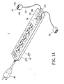
- FIG. 1A illustrates an exploded diagram of a first embodiment of the detachable electrical power receptacle in accordance with certain aspects of the present technique in an exposed mode
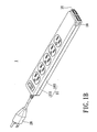
- FIG. 1B illustrates an exploded diagram of the first embodiment of the detachable electrical power receptacle in accordance with certain aspects of the present technique in a concealed mode
- FIG. 2 illustrates an exploded diagram of a second embodiment of the detachable electrical power receptacle according to the present invention
- FIG. 3 illustrates an exploded diagram of a third embodiment of the detachable electrical power receptacle according to the present invention
- FIG. 4 illustrates an exploded diagram of a fourth embodiment of the detachable electrical power receptacle according to the present invention
- FIG. 5 illustrates a diagram of an embodiment in accordance with the detachable electrical power receptacle according to the present invention in use.
- FIG. 6 illustrates a diagram of another embodiment in accordance with the detachable electrical power receptacle according to the present invention in use.
- a detachable electrical power receptacle 1 comprises a main body 10, at least one extension socket 16, at least one extension power cord 141, a coil reel 14, a power unit 24, and an electrical power plug 26.
- the main body 10 further includes a first housing member 101, a second housing member 103, at least one outlet hole 105, and an accommodating section 107.
- the extension socket 16, includes a third housing member 161 and a fourth housing member163.
- the main body 10 is formed by connecting the first housing member 101 to the second housing member 103.
- the main body 10 has the electrical power plug 26 which functions by electrically connecting a power supply source and has the outlet hole 105.
- the outlet hole 105 may be designed to allow the extension power cord 141 wrapped on the coil reel 14 inside the main body to pass through.
- An end of the extension power cord 141 connects to the main body 10 and the other end thereof connects to the extension socket 16.
- the extension socket 16 is formed by connecting the third housing member 161 to the fourth housing member.
- the outlet hole 105 may be disposed on a surface of the first housing member 101 nearby the accommodating section 107.
- the accommodating section 107 is designed to receive the extension socket 16.
- the main body 10 of the detachable electrical power receptacle 1 may apply the extension power cord 14 to make the extension socket 16 to be disengaged from the main body 10 in a specific distance, i.e., the exposed length of the extension power cord 14, or to be engaged with the main body 10.
- the coil reel 14 may electrically connect to the power unit 24.
- the power unit 24 is capable of performing power conversion processing for the electrical power supplying from the power supply source, e.g., the public electrical power distribution system, connected to the electrical power plug 26, so as to output the rectified output power to the extension socket 16.
- the power unit 14 may connect to the extension power cord 141 electrically.
- the connecting relationship is merely for illustration, but is not limited thereto.
- the coil reel 14 of the detachable electrical power receptacle 1 is used to wind the extension power cord 141. Therefore, the length of the extension power cord 141 may be varied according to the winding actions of the coil reel 14, so that the extension socket 16 connected to the extension power cord 151 may be tightly engaged with the main body 10 or disengaged or departed from the main body 10, thereby the effective utilization range of the extension socket 16 is adjusted.
- the winding method of the extension power cord 141 may be an automatically winding method or a manually winding method. In the embodiment, the automatically winding method is taken as an example for illustration, but is not limited thereto.
- the extension socket 16 may be any different kinds of power connectors as being obvious for the ones skilled in the art, e.g., a universal serial bus (USB) jack or a RJ45, etc.
- the exposed length of extension power cord 141 out of the main body may be capable of lengthening, such that the extension socket 16 is disengaged from the accommodating section 107, thereby expanding the utilization range of the extension socket 16 as shown in FIG. 1A .
- the length of extension power cord 141 may be shortening so as to allow the extension socket 16 to be engaged to the accommodating section 107 of the main body 10, as shown in FIG. 1B .
- the users may length or shorten the length of the extension power cord 141, i.e., adjusting effective charging range of the extension socket 16, with respect to different conditions in use, so that the users may not require to perform an additional action, e.g., bending or walking, to utilize the extension socket 16, thereby increasing the convenience in use. Meanwhile, it also prevents the troublesome and inconvenience to carry additional charging connectors and the corresponding extension power cords thereof.
- FIG. 2 in conjunction with FIG 1A , in which an exploded diagram of a second embodiment of the detachable electrical power receptacle according to the present invention is demonstrated.
- a detachable electrical power receptacle 1a has identical components and similar connecting relationship with respect to that of FIG.1A and FIG. 1B .
- the only structural difference, however, is a location design regarding the accommodating section 107a.
- the accommodating section 107a has a first accommodating space 1070 and a second accommodating space 1072.
- the first accommodating space 1070 is disposed on a periphery of the main body 10a and the second accommodating space 1072 is disposed on a middle section of the main body 10a.
- an extension power cord 141 passed thru an outlet hole 105 adjacent to the first accommodating space 1070 connects to a first USB (Universal Serial Bus) jack 165; an extension power cord 141' passed thru an outlet hole 105' adjacent to the second accommodating space 1072 connects to a second USB (Universal Serial Bus) jack 167.
- the configuration design of the accommodating section 107a and the quantity of the universal serial bus jacks 165, 167 are demonstrated for reference, but not limited thereto.
- the detachable electrical power receptacle 1a further includes a power switch 18, an indicator 20, and at least one electrical outlet assembly 12.
- the power switch 18 is disposed on the main body 10a to allow the users to control the electrical power by turning on or off the power switch 18.
- the indicator 20 may be a light emitting diode (LED) indicator which is disposed on the main body 10a to demonstrate operating information of the detachable electrical power receptacle 1a.
- LED light emitting diode
- the indicator 20 is emitting light, it means the power supply source is supplying the electrical power and the detachable electrical power receptacle is in a conduction mode; if the indicator 20 is not emitting light, it means the power supply source is not supplying the electrical power to the detachable electrical power receptacle 1a. Thus, the detachable electrical power receptacle 1a is in a cutoff mode.
- At least one of the electrical outlet assemblies 12 is disposed on the main body 10a.
- the plurality of electrical outlet assemblies 12 may be either one or a combination of three-slot or two-slot electrical outlets.
- FIG. 3 in which an exploded diagram of a third embodiment of the detachable electrical power receptacle according to the present invention is shown.
- a detachable electrical power receptacle 1b has identical components and similar connecting relationship with respect to that of FIG.1A . The only structural difference, however, is a location design regarding the coil reel 14b. The coil reel 14b is disposed between the main body 10 and the extension socket 16b.
- FIG. 4 in which an exploded diagram of a fourth embodiment of the detachable electrical power receptacle according to the present invention is shown.
- a detachable electrical power receptacle 1c has identical components and similar connecting relationship with respect to that of FIG.1A .
- the extension power cord 141c connected to the main body 10c and the extension socket 16c, may be arranged in order outside the main body 10c and the extension socket 16c without depending on any specific tools, i.e., coil reel.
- the extension power cord 141 c may be winded up, collected, and received in any spaces; conversely, the extension power cord 141c may not be winded up and may be exposed out arbitrarily.
- the aforementioned embodiments are taken for illustration, but not limited thereto.
- FIG. 5 a diagram of an embodiment in accordance with the detachable electrical power receptacle according to the present invention in use is demonstrated.
- the extension socket 16 of the detachable electrical power receptacle 1 may be pulled from the ground to the desktop according to the existence of the extension power cord 141, so that the users may apply the extension socket 16 directly to connect to an electronic device 3, e.g., a cell phone or a digital camera, for charging the operations conveniently. Furthermore, the users are not required to bring along other external charging connectors or cords for charging the electronic device 3, thereby increasing the convenience in use.
- the extension socket 16 may be managed to be engaged or disengaged from the main body so as to improve the convenience in use and expand the charging operation range.
- FIG. 6 in conjunction with FIG. 1A , in which a diagram of another embodiment in accordance with the detachable electrical power receptacle according to the present invention in use is demonstrated.
- the extension socket 16 disengaged from the main body 10 in the exposed mode may cooperate with a binding section 221 which is designed specifically.
- the binding section 221 may be designed on a charging cradle 22.
- the binding section 221 is provided for the extension socket 16 to incorporate with the charging cradle 22, so that the charging cradle 22 and the extension socket 16 may function as a unit to facilitate the charging operations of the electronic device 3 on the charging cradle 22.
- the charging cradle 22 may be formed by a bendable thin plastic sheet or a bendable thick paper, but is not limited thereto.
- the extension socket 16 may hang on or attach to the binding section 221.
- the connection methods aforementioned are merely for illustration, but not limited thereto.
- the detachable electrical power receptacle according which has a simplified structure design with low production cost according to the present invention applies the extension power cord for increasing the convenience in using the extension sockets and the extension power cords to charge the portable electronic device directly.
- the technical feature for adjusting the length of the extension power cord is utilized to allow the extension socket to be able to be applied in a larger and wider area.
- the extension socket may be disengaged from the accommodating section and the length of the extension power cord may be adjusted in the exposed mode, so as to improve the convenience of the charging operations as the extension socket is in use.
- the extension power cord when the extension socket is not in use, the extension power cord may be winded up to reduce the overall length thereof, so that the extension socket may be received completely in the accommodating section of the detachable electrical power receptacle in the concealed mode. Even though there is no design for the accommodating section, the extension socket may be attached to the outer surface of the main body. By adjusting the length of the extension power cord, the effective area for the charging operations of the extension socket is adjustable, thereby reducing the restrictions and the inconvenience in charging operations.
Landscapes
- Engineering & Computer Science (AREA)
- General Engineering & Computer Science (AREA)
- Theoretical Computer Science (AREA)
- Computer Hardware Design (AREA)
- Physics & Mathematics (AREA)
- General Physics & Mathematics (AREA)
- Charge And Discharge Circuits For Batteries Or The Like (AREA)
- Connector Housings Or Holding Contact Members (AREA)
- Details Of Connecting Devices For Male And Female Coupling (AREA)
Applications Claiming Priority (1)
| Application Number | Priority Date | Filing Date | Title |
|---|---|---|---|
| TW99106592A TW201131913A (en) | 2010-03-08 | 2010-03-08 | Detachable electrical power receptacle |
Publications (2)
| Publication Number | Publication Date |
|---|---|
| EP2365590A2 true EP2365590A2 (de) | 2011-09-14 |
| EP2365590A3 EP2365590A3 (de) | 2011-09-28 |
Family
ID=44009935
Family Applications (1)
| Application Number | Title | Priority Date | Filing Date |
|---|---|---|---|
| EP20100162540 Withdrawn EP2365590A3 (de) | 2010-03-08 | 2010-05-11 | Herausnehmbarer elektrischer Versorgungsanschluss |
Country Status (4)
| Country | Link |
|---|---|
| US (1) | US20110215759A1 (de) |
| EP (1) | EP2365590A3 (de) |
| JP (1) | JP2011187429A (de) |
| TW (1) | TW201131913A (de) |
Cited By (2)
| Publication number | Priority date | Publication date | Assignee | Title |
|---|---|---|---|---|
| WO2015140232A3 (de) * | 2014-03-20 | 2016-03-31 | Markus Fischer | Mobiles ladegerät zum laden von geräten über einen ladeanschluss |
| CN105790004A (zh) * | 2016-05-04 | 2016-07-20 | 宁波唯尔电器有限公司 | 便携式绕线盘 |
Families Citing this family (27)
| Publication number | Priority date | Publication date | Assignee | Title |
|---|---|---|---|---|
| US9559472B2 (en) * | 2013-04-25 | 2017-01-31 | Tseng-Lu Chien | Wire arrangement for hand-reachable USB charger related devices |
| US20170321853A1 (en) * | 2009-11-19 | 2017-11-09 | Tseng-Lu Chien | Wire Arrangement for Hand-Reachable USB Charger Related Devices |
| US11137121B2 (en) | 2009-11-19 | 2021-10-05 | Tseng-Lu Chien | USB device has separated distance away USB-unit(s) by branch-wire(s) |
| DE102010002565B8 (de) * | 2010-03-04 | 2012-03-22 | Tyco Electronics Amp Gmbh | Anschlussvorrichtung für ein Solarmodul |
| US8758045B2 (en) | 2010-03-12 | 2014-06-24 | Scosche Industries, Inc. | Portable universal serial bus (USB) cable keychain assembly with carabiner clip |
| US7942691B1 (en) * | 2010-03-12 | 2011-05-17 | Scosche Industries, Inc. | Universal serial bus cable (USB) cable assembly having ports to slidably receive upstream and downstream connectors |
| US11746047B2 (en) * | 2010-11-19 | 2023-09-05 | Aaron Chien | Wired and detachable charging-unit of electric product |
| FR2977970B1 (fr) * | 2011-07-15 | 2014-01-03 | Sagem Defense Securite | Cartouche de communication amovible d'un equipement, equipement, ensemble et systeme correspondants |
| US9197053B2 (en) * | 2014-01-13 | 2015-11-24 | International Business Machines Corporation | Retractable interconnect device including multiple electrical paths |
| US9166346B2 (en) | 2014-01-13 | 2015-10-20 | International Business Machines Corporation | Retractable interconnect device configured to switch between electrical paths |
| CA3133606C (en) * | 2014-05-07 | 2022-09-20 | Hubbell Incorporated | Integrated modular multimedia system in wall-box format |
| WO2016033531A1 (en) * | 2014-08-28 | 2016-03-03 | Macauda Tom | Electrical power cord with supplemental socket |
| US9484693B1 (en) * | 2015-06-11 | 2016-11-01 | Tyler James Richter | Cord organizing assembly |
| CN105514735A (zh) * | 2016-01-27 | 2016-04-20 | 刘梦茹 | 一种多插插座 |
| US9876324B2 (en) | 2016-05-04 | 2018-01-23 | Data:)Comm Electronics, Inc. | Retractable wall mounted electrical plug for charging communication devices |
| US10199783B2 (en) * | 2016-08-26 | 2019-02-05 | Valiant Innovations, LLC | Extendable modular power strip system and method of use |
| CN106252969B (zh) * | 2016-09-07 | 2018-11-02 | 广东百事泰电子商务股份有限公司 | 可拆装组合式智能插座装置 |
| CA2988193A1 (en) | 2016-12-09 | 2018-06-09 | Norman R. Byrne | Cushion-mounted electrical outlets |
| USD928093S1 (en) | 2017-05-31 | 2021-08-17 | Norman R. Byrne | Portable power and data receptacle for furniture |
| US10950990B2 (en) | 2018-04-02 | 2021-03-16 | One-Eyed Pilot Innovations, Inc. | Reel based outlet relocation/extension system |
| USD951869S1 (en) | 2018-07-13 | 2022-05-17 | One-Eyed Pilot Innovations, Inc. | Wall socket extender |
| US10658800B1 (en) * | 2019-01-22 | 2020-05-19 | Trinise D. Luster | Power supply assembly |
| US10566746B1 (en) * | 2019-01-29 | 2020-02-18 | George Breeden | Illuminated electricity distribution device |
| US11600998B2 (en) * | 2019-04-12 | 2023-03-07 | Anthony Walker | Electronic device charger |
| US10700482B1 (en) * | 2019-05-12 | 2020-06-30 | Richard Vela | Retrofit kit with extendable and retractable electrical sockets for electrical gang boxes |
| JP7165928B2 (ja) * | 2020-12-03 | 2022-11-07 | パナソニックIpマネジメント株式会社 | テーブルタップ |
| US20240388077A1 (en) * | 2023-05-20 | 2024-11-21 | PJ Antonik | Retractable Cord |
Family Cites Families (10)
| Publication number | Priority date | Publication date | Assignee | Title |
|---|---|---|---|---|
| JPS61194966U (de) * | 1985-05-29 | 1986-12-04 | ||
| US6433274B1 (en) * | 2000-01-06 | 2002-08-13 | Mobility Electronic, Inc. | Power converter device |
| US6744150B2 (en) * | 2001-12-03 | 2004-06-01 | Neven V. Rendic | Outlet strip controlled by PC using low voltage powertap |
| DE602004010362T2 (de) * | 2004-02-06 | 2008-09-25 | Centritech Ltd. | Eine Steckdosenleiste |
| TWI255572B (en) * | 2004-05-05 | 2006-05-21 | Advanced Connectek Inc | A portable electrical power unit with transmission display |
| US20070275594A1 (en) * | 2006-05-23 | 2007-11-29 | United Technologies Corporation | Multipurpose power center |
| US7812478B1 (en) * | 2007-01-15 | 2010-10-12 | Menas Gregory W | Power sampling systems and methods |
| US7909624B2 (en) * | 2007-03-26 | 2011-03-22 | Belkin International, Inc. | Carabiner universal serial bus hub |
| TWI360268B (en) * | 2008-02-05 | 2012-03-11 | Remote control duo power set | |
| JP3141522U (ja) * | 2008-02-25 | 2008-05-08 | 權威電科技有限公司 | 電源アダプタ |
-
2010
- 2010-03-08 TW TW99106592A patent/TW201131913A/zh unknown
- 2010-04-28 US US12/769,168 patent/US20110215759A1/en not_active Abandoned
- 2010-05-11 EP EP20100162540 patent/EP2365590A3/de not_active Withdrawn
- 2010-05-28 JP JP2010123233A patent/JP2011187429A/ja active Pending
Non-Patent Citations (1)
| Title |
|---|
| None |
Cited By (3)
| Publication number | Priority date | Publication date | Assignee | Title |
|---|---|---|---|---|
| WO2015140232A3 (de) * | 2014-03-20 | 2016-03-31 | Markus Fischer | Mobiles ladegerät zum laden von geräten über einen ladeanschluss |
| CN105790004A (zh) * | 2016-05-04 | 2016-07-20 | 宁波唯尔电器有限公司 | 便携式绕线盘 |
| CN105790004B (zh) * | 2016-05-04 | 2018-04-06 | 宁波唯尔电器有限公司 | 便携式绕线盘 |
Also Published As
| Publication number | Publication date |
|---|---|
| TW201131913A (en) | 2011-09-16 |
| EP2365590A3 (de) | 2011-09-28 |
| US20110215759A1 (en) | 2011-09-08 |
| JP2011187429A (ja) | 2011-09-22 |
Similar Documents
| Publication | Publication Date | Title |
|---|---|---|
| US20110215759A1 (en) | Detachable electrical power receptacle | |
| US11445626B2 (en) | Power outlet module including USB plug in location other than outlet face | |
| CN207116873U (zh) | 快充转接头及快充线缆结构 | |
| US8696368B2 (en) | Wall mountable universal serial bus and alternating current power sourcing receptacle | |
| US20080211310A1 (en) | Portable power supply apparatus capable of receiving ac or dc input power | |
| US20120081087A1 (en) | Hub device capable of supply power | |
| US20090309542A1 (en) | Multi-input charger | |
| US20060044302A1 (en) | Notebook DC power sharing arrangement | |
| US20090061668A1 (en) | Pass-through grounding plug | |
| CN204316152U (zh) | 插头式充电器 | |
| WO2009061018A1 (en) | Multi adapter | |
| CN102195222A (zh) | 可分离供电的插座装置 | |
| CN204615121U (zh) | 电子转接头 | |
| CN104836268A (zh) | 容易携带的充电器 | |
| US20160336777A1 (en) | Fixed charging unit having retractable charging cables | |
| EP1936790A2 (de) | Tragbares Netzteil mit Gleich- und Wechselstromeingang | |
| US20090310384A1 (en) | AC-DC input adapter | |
| US20090113089A1 (en) | Sound box with usb interface | |
| US20150357919A1 (en) | Method and system for variable output power supply | |
| KR20090077411A (ko) | 직류전원장치 내장 전원소켓장치 제조기술 | |
| CN203250953U (zh) | 一种便携式多功能电源 | |
| CN207968005U (zh) | 具有调压结构的充电装置 | |
| AU2011101657B4 (en) | Adaptor | |
| US20120068535A1 (en) | Energy converter, and associated method, for providing converted energy to a set of electronic devices | |
| KR20160054917A (ko) | 무선 통신 기능을 구비한 멀티탭 |
Legal Events
| Date | Code | Title | Description |
|---|---|---|---|
| PUAI | Public reference made under article 153(3) epc to a published international application that has entered the european phase |
Free format text: ORIGINAL CODE: 0009012 |
|
| PUAL | Search report despatched |
Free format text: ORIGINAL CODE: 0009013 |
|
| AK | Designated contracting states |
Kind code of ref document: A2 Designated state(s): AL AT BE BG CH CY CZ DE DK EE ES FI FR GB GR HR HU IE IS IT LI LT LU LV MC MK MT NL NO PL PT RO SE SI SK SM TR |
|
| AX | Request for extension of the european patent |
Extension state: BA ME RS |
|
| RIC1 | Information provided on ipc code assigned before grant |
Ipc: G06F 1/26 20060101ALI20110818BHEP Ipc: H01R 31/02 20060101ALI20110818BHEP Ipc: H01R 27/02 20060101ALI20110818BHEP Ipc: H01R 13/72 20060101ALI20110818BHEP Ipc: H01R 13/60 20060101AFI20110818BHEP |
|
| AK | Designated contracting states |
Kind code of ref document: A3 Designated state(s): AL AT BE BG CH CY CZ DE DK EE ES FI FR GB GR HR HU IE IS IT LI LT LU LV MC MK MT NL NO PL PT RO SE SI SK SM TR |
|
| AX | Request for extension of the european patent |
Extension state: BA ME RS |
|
| RAP1 | Party data changed (applicant data changed or rights of an application transferred) |
Owner name: POWERTECH INDUSTRIAL CO. LTD. |
|
| 17P | Request for examination filed |
Effective date: 20120309 |
|
| STAA | Information on the status of an ep patent application or granted ep patent |
Free format text: STATUS: THE APPLICATION IS DEEMED TO BE WITHDRAWN |
|
| 18D | Application deemed to be withdrawn |
Effective date: 20131201 |