EP2365592A2 - Elektrische Steckvorrichtung - Google Patents
Elektrische Steckvorrichtung Download PDFInfo
- Publication number
- EP2365592A2 EP2365592A2 EP11157185A EP11157185A EP2365592A2 EP 2365592 A2 EP2365592 A2 EP 2365592A2 EP 11157185 A EP11157185 A EP 11157185A EP 11157185 A EP11157185 A EP 11157185A EP 2365592 A2 EP2365592 A2 EP 2365592A2
- Authority
- EP
- European Patent Office
- Prior art keywords
- plug
- sealing contour
- sealing
- contour
- receptacle
- Prior art date
- Legal status (The legal status is an assumption and is not a legal conclusion. Google has not performed a legal analysis and makes no representation as to the accuracy of the status listed.)
- Granted
Links
Images


Classifications
-
- H—ELECTRICITY
- H01—ELECTRIC ELEMENTS
- H01R—ELECTRICALLY-CONDUCTIVE CONNECTIONS; STRUCTURAL ASSOCIATIONS OF A PLURALITY OF MUTUALLY-INSULATED ELECTRICAL CONNECTING ELEMENTS; COUPLING DEVICES; CURRENT COLLECTORS
- H01R24/00—Two-part coupling devices, or either of their cooperating parts, characterised by their overall structure
- H01R24/76—Two-part coupling devices, or either of their cooperating parts, characterised by their overall structure with sockets, clips or analogous contacts and secured to apparatus or structure, e.g. to a wall
- H01R24/78—Two-part coupling devices, or either of their cooperating parts, characterised by their overall structure with sockets, clips or analogous contacts and secured to apparatus or structure, e.g. to a wall with additional earth or shield contacts
-
- H—ELECTRICITY
- H01—ELECTRIC ELEMENTS
- H01R—ELECTRICALLY-CONDUCTIVE CONNECTIONS; STRUCTURAL ASSOCIATIONS OF A PLURALITY OF MUTUALLY-INSULATED ELECTRICAL CONNECTING ELEMENTS; COUPLING DEVICES; CURRENT COLLECTORS
- H01R13/00—Details of coupling devices of the kinds covered by groups H01R12/70 or H01R24/00 - H01R33/00
- H01R13/46—Bases; Cases
- H01R13/52—Dustproof, splashproof, drip-proof, waterproof, or flameproof cases
- H01R13/5216—Dustproof, splashproof, drip-proof, waterproof, or flameproof cases characterised by the sealing material, e.g. gels or resins
-
- H—ELECTRICITY
- H01—ELECTRIC ELEMENTS
- H01R—ELECTRICALLY-CONDUCTIVE CONNECTIONS; STRUCTURAL ASSOCIATIONS OF A PLURALITY OF MUTUALLY-INSULATED ELECTRICAL CONNECTING ELEMENTS; COUPLING DEVICES; CURRENT COLLECTORS
- H01R13/00—Details of coupling devices of the kinds covered by groups H01R12/70 or H01R24/00 - H01R33/00
- H01R13/46—Bases; Cases
- H01R13/52—Dustproof, splashproof, drip-proof, waterproof, or flameproof cases
- H01R13/5219—Sealing means between coupling parts, e.g. interfacial seal
-
- H—ELECTRICITY
- H01—ELECTRIC ELEMENTS
- H01R—ELECTRICALLY-CONDUCTIVE CONNECTIONS; STRUCTURAL ASSOCIATIONS OF A PLURALITY OF MUTUALLY-INSULATED ELECTRICAL CONNECTING ELEMENTS; COUPLING DEVICES; CURRENT COLLECTORS
- H01R24/00—Two-part coupling devices, or either of their cooperating parts, characterised by their overall structure
- H01R24/66—Two-part coupling devices, or either of their cooperating parts, characterised by their overall structure with pins, blades or analogous contacts and secured to apparatus or structure, e.g. to a wall
- H01R24/70—Two-part coupling devices, or either of their cooperating parts, characterised by their overall structure with pins, blades or analogous contacts and secured to apparatus or structure, e.g. to a wall with additional earth or shield contacts
-
- H—ELECTRICITY
- H01—ELECTRIC ELEMENTS
- H01R—ELECTRICALLY-CONDUCTIVE CONNECTIONS; STRUCTURAL ASSOCIATIONS OF A PLURALITY OF MUTUALLY-INSULATED ELECTRICAL CONNECTING ELEMENTS; COUPLING DEVICES; CURRENT COLLECTORS
- H01R13/00—Details of coupling devices of the kinds covered by groups H01R12/70 or H01R24/00 - H01R33/00
- H01R13/46—Bases; Cases
- H01R13/52—Dustproof, splashproof, drip-proof, waterproof, or flameproof cases
- H01R13/5213—Covers
-
- H—ELECTRICITY
- H01—ELECTRIC ELEMENTS
- H01R—ELECTRICALLY-CONDUCTIVE CONNECTIONS; STRUCTURAL ASSOCIATIONS OF A PLURALITY OF MUTUALLY-INSULATED ELECTRICAL CONNECTING ELEMENTS; COUPLING DEVICES; CURRENT COLLECTORS
- H01R2103/00—Two poles
Definitions
- the present invention relates to a socket for receiving an electrical connector, consisting of a base housing comprising a mounting flange and an integrally made with this, Steckerstattingn having plug receptacle, and a sealing contour which rests in the inserted state of the plug to this and the plug with the Connector receptacle tightly connects.
- the present invention further relates to an electrical plug-in device system consisting of a plug and a socket, which consists of a base housing comprising a mounting flange and an integrally made with this, Steckerstattingn having plug receptacle, and a sealing contour, wherein in the inserted state of the plug, the sealing contour of Socket on the plug rests and this tightly connects to the connector receptacle.
- Sockets of plug-in device systems of this type are provided on the one hand for mobile use, for example in line rollers, power strips and mobile distributors on the other hand, but also for installation on a stationary support, for example on a wall or a cabinet.
- VDE 0620-1 The standard to be applied in the present case is VDE 0620-1, which makes special demands on the tightness against water ingress of such plug-in device systems.
- a standard-compliant design of such plug-in device systems requires that they comply with protection class IP44 or IP54.
- TPE rubber or thermoplastic elastomer
- a soft material at a socket made of a thermoplastic such as polyamide (PA), polyethylene (PE), polypropylene (PP), polycarbonate (PC) , Acrylonitrile-butadiene-styrene (ABS), which are each a relative to the rubber or thermoplastic elastomer hard material was fixed, for example, by molding or screwing, which sealing contour after plugging the plug into the socket sealingly comes to rest on the plug and so prevents the ingress of water into the plug receptacle of the socket.
- PA polyamide
- PE polyethylene
- PP polypropylene
- PC polycarbonate
- ABS Acrylonitrile-butadiene-styrene
- the material of the sealing contour used hitherto due to its softness, is susceptible to mechanical influences from the outside and the material properties change nonlinearly over time and temperature.
- VDE 0620-1 subordinate socket or a standard subjacent Steckvoriquesssystem which is simple in construction, easier to manufacture, less sensitive to external mechanical effects and less expensive to produce.
- this is at a socket for receiving an electrical connector, consisting of a base housing comprising a mounting flange and an integrally manufactured with this, Steckerstattingn having plug receptacle, and a sealing contour which rests in the inserted state of the plug to this and the plug with the plug receptacle tight connects, thereby achieving that the sealing contour and the base housing are made of the same material, that the sealing contour has a tubular shape, and that the plug receptacle consists of two sections, wherein a first portion seen in the insertion direction of the plug, behind a connector facing mounting flange surface is arranged and cup-shaped and a second section in front of the Plug facing mounting flange surface is arranged.
- mounting flange, connector receptacle and sealing contour can be produced in a single injection process.
- a classical sealing contour from the mounting flange softer material is not required, but also by using a sealing contour of the harder material of the base housing, such as a thermoplastic, which can be achieved to meet the standard required tightness.
- the production of the sealing contour of the harder material of the base housing also has the advantage that the sealing contour is more resistant to external influences.
- the sealing contour has a sleeve-like shape, so that it surrounds the plug on all sides and rests against this.
- the wall thickness of the sealing contour according to the invention is less than 1.2 mm, preferably less than 0.8 mm. It has been found that this wall thickness in combination with the material from which the sealing contour is made according to the invention, is optimally suited to meet the requirements of the standard VDE 0620-1 with respect to water tightness. A larger wall thickness would cause the plug can not be properly inserted into the connector receptacle, because the sealing contour would oppose the insertion too high resistance due to their rigidity.
- the second section is constructed sleeve-shaped.
- the sleeve-shaped second portion forms an extension of the cup-shaped first portion of the plug receptacle opposite to the plugging direction of the plug, and the sealing contour is at a Plug facing end portion of the second portion and forms an extension thereof in the direction of the plug.
- the formation of the sealing contour as an extension of the connector receptacle allows a particularly simple production, since the mold used for the production of the socket can continue to do without a core.
- the second, facing from the plug top of the mounting flange in opposite to the insertion of the plug protruding portion of the connector receptacle has a greater wall thickness than the sealing contour. This makes it possible that the transition of the sealing contour in this second portion of the connector receptacle due to the differences in the wall thickness, the sealing contour is slightly pivotable about this area.
- the wall thickness of the second portion of the connector receptacle is to be chosen so that it is essentially unyielding and rigid in the provided by the standard for the purposes of compliance with protection IP44 and IP54 insertion force, whereas the wall thickness of the sealing contour, is selected so that when inserting the plug into the plug receptacle with the insertion force provided by the standard, the sealing contour is slightly outward, away from the axis of the plug and the plug receptacle pivotable or expandable or compressible, so that although made according to the invention of the same material, the sealing contour can fit particularly well on the plug and meet the requirements for tightness.
- the ratio of the wall thicknesses of the sealing contour and the second section of the plug receptacle is less than 1/4, but preferably between 1/2 and 1/4.
- the plug is provided in a preferred embodiment of the invention in the region of impingement of a sealing edge of the sealing contour with a run-on slope.
- the surface of the plug viewed in the plug-in direction of the plug before the run-on slope, has a sealing edge on which the sealing edge of the sealing contour comes to lie sealingly in the plugged state of the plug.
- the sealing edge of the sealing contour ensures optimum sealing.
- the design or arrangement of the sealing edge is crucial.
- the sealing contour has an end face which, at the same time, viewed in the insertion direction of the plug, is the first end face of the base housing, and in that this end face forms a sealing edge with an inner surface of the sealing contour.
- a second section 9 is arranged in the plug-in direction 10 of the plug in front of this plug-facing mounting flange 8 and has a substantially tubular shape. It forms an extension of the first section 7 and houses not only guide elements 12 but also ground contacts 13.
- the length a of the sealing contour 5, and the length b of the second portion 9 of the connector receptacle 3 and the depth c of the first portion 7 of the connector receptacle 3 thus together form the entire available insertion depth of the connector receptacle.
- the sealing contour 5 has a smaller wall thickness than the second section 9 of the plug receptacle 3 and is thereby slightly pivotable about the end 14 of the second section 9 or the sleeve-shaped sealing contour 5 can thereby slightly expand up to the end 14.
- sealing contour 5 and second section 9 can still by one or more, preferably in the insertion direction 10 extending stiffening webs 4a, 4b (see Figure 6 ), which preferably extend from the mounting flange surface 8 to the free end of the sealing contour 5, wherein their extent in the circumferential direction of the sealing contour 5, however, less than 10% of the circumference of the sealing contour 5 makes.
- the sealing contour 5 with its inner sealing edge 15 seals against the surface of the plug 6.
- the absolute wall thickness of the sealing contour 5 is less than 1.2 mm, preferably less than 0.8 mm, so that the sealing contour 5 the insertion of the plug 6 is not too much resistance oppose and, if necessary, be slightly distended.
- the ratio of the wall thickness of the sealing contour 5 to the sleeve-shaped, second portion 9 of the connector receptacle 3 is less than 1/4, but preferably between 1/2 and 1/4, so that the second section 9 forms a kind of rigid foundation for the sealing contour 5 arranged thereon and movable to a small extent, in particular expandable.
- the surface of the plug 6 is provided in the region of the impact of the sealing edge 15 with a run-on slope 16, in front of which in the insertion direction 10 seen a substantially parallel to the axis 19 extending sealing edge 17 is arranged.
- the sealing edge 15 comes to lie on the sealing edge 17 whereby the penetration of water into the connector receptacle 3 is prevented.
- Figure 9 shows detail C. Figure 8 , wherein the interaction between the sealing edge 15 of the sealing contour 5 and the sealing edge 17 of the plug 6 is clearly visible. As a result, an optimal seal is achieved, wherein the embodiment or
- the sealing edge 15 is formed by the end face (no separate reference number) of the sealing contour 5 and the inner surface 18 of the sealing contour 5.
- the end face of the sealing contour 5 at the same time, seen in the insertion direction 10 of the plug 6, the first end face of the base housing 1.
- the inner surface 18 of the sealing contour 5 is particularly in Figure 5 clearly visible.
Landscapes
- Chemical & Material Sciences (AREA)
- Dispersion Chemistry (AREA)
- Connector Housings Or Holding Contact Members (AREA)
Abstract
Description
- Die vorliegende Erfindung bezieht sich auf eine Steckdose zur Aufnahme eines elektrischen Steckers, bestehend aus einem Grundgehäuse umfassend einen Montageflansch und eine einstückig mit diesem hergestellte, Steckerstiftaufnahmen aufweisende Steckeraufnahme, sowie einer Dichtkontur, welche im gesteckten Zustand des Steckers an diesem anliegt und den Stecker mit der Steckeraufnahme dicht verbindet.
- Die vorliegende Erfindung bezieht sich außerdem auf ein elektrisches Steckvorrichtungssystem bestehend aus einem Stecker und einer Steckdose, die aus einem Grundgehäuse umfassend einen Montageflansch und eine einstückig mit diesem hergestellte, Steckerstiftaufnahmen aufweisende Steckeraufnahme, sowie einer Dichtkontur besteht, wobei im gesteckten Zustand des Steckers die Dichtkontur der Steckdose am Stecker anliegt und diesen mit der Steckeraufnahme dicht verbindet.
- Steckdosen von Steckvorrichtungssystemen dieser Art sind einerseits für den mobilen Einsatz vorgesehen, beispielsweise in Leitungsrollern, Steckdosenleisten und mobilen Verteilern andererseits aber auch für den Einbau an einem stationären Träger, beispielsweise an einer Wand oder einem Schaltschrank.
- Die im vorliegenden Fall anzuwendende Norm ist die VDE 0620-1, welche spezielle Anforderungen an die Dichtheit gegen Wassereintritt solcher Steckvorrichtungssysteme stellt. Eine normgerechte Ausführung solcher Steckvorrichtungssysteme verlangt, dass diese der Schutzart IP44 bzw. IP54 genügen.
- Bislang wurden diese Anforderungen dadurch erfüllt, dass eine Dichtkontur aus Gummi oder thermoplastischem Elastomer (TPE), einem weichen Material, an einer Steckdose aus einem Thermoplasten wie beispielsweise Polyamid (PA), Polyethylen (PE), Polypropylen (PP), Polycarbonat (PC), Acrylnitril-Butadien-Styrol (ABS), welche jeweils ein relativ zum Gummi oder thermoplastischen Elastomer hartes Material darstellen, fixiert wurde, beispielweise durch Anspritzen oder Aufschrauben, welche Dichtkontur nach dem Einstecken des Steckers in die Steckdose abdichtend am Stecker zum Anliegen kommt und so das Eindringen von Wasser in die Steckeraufnahme der Steckdose verhindert.
- Das zusätzliche Anbringen einer solchen Dichtkontur verkompliziert jedoch den Aufbau einer gattungsgemäßen Steckdose insbesondere deren Herstellung, da ein separater Arbeitsschritt erforderlich ist.
- Hinzukommt, dass das bislang eingesetzte Material der Dichtkontur aufgrund seiner Weichheit anfällig gegen mechanische Einwirkungen von außen ist und sich die Werkstoffeigenschaften nichtlinear über Zeit und Temperatur verändern.
- Es ist daher die Aufgabe der vorliegenden Erfindung, eine VDE 0620-1 unterliegende Steckdose bzw. ein dieser Norm unterliegendes Steckvorrichtungssystem vorzuschlagen, welches einfach im Aufbau ist, einfacher in der Herstellung, weniger empfindlich gegenüber äußeren mechanischen Einwirkungen und kostengünstiger herstellbar.
- Erfindungsgemäß wird dies bei einer Steckdose zur Aufnahme eines elektrischen Steckers, bestehend aus einem Grundgehäuse umfassend einen Montageflansch und eine einstückig mit diesem hergestellte, Steckerstiftaufnahmen aufweisende Steckeraufnahme, sowie einer Dichtkontur, welche im gesteckten Zustand des Steckers an diesem anliegt und den Stecker mit der Steckeraufnahme dicht verbindet, dadurch erreicht, dass die Dichtkontur und das Grundgehäuse aus demselben Material gefertigt sind, dass die Dichtkontur hülsenförmige Gestalt aufweist, und dass die Steckeraufnahme aus zwei Abschnitten besteht, wobei ein erster Abschnitt in Steckrichtung des Steckers gesehen, hinter einer dem Stecker zugewandten Montageflanschoberfläche angeordnet ist und topfförmige Gestalt aufweist und ein zweiter Abschnitt vor der dem Stecker zugewandten Montageflanschoberfläche angeordnet ist.
- Dadurch können Montageflansch, Steckeraufnahme und Dichtkontur in einem einzigen Spritzvorgang hergestellt werden. Überraschenderweise hat sich herausgestellt, dass das Vorsehen einer klassischen Dichtkontur aus gegenüber dem Montageflansch weicherem Material nicht erforderlich ist, sondern auch durch Einsatz einer Dichtkontur aus dem härteren Material des Grundgehäuses, beispielsweise einem Thermoplast, die für die Erfüllung der Norm erforderliche Dichtheit erzielt werden kann.
- Die Herstellung der Dichtkontur aus dem härteren Material des Grundgehäuses hat außerdem den Vorteil, dass die Dichtkontur widerstandsfähiger gegenüber äußeren Einflüssen ist.
- Die Dichtkontur hat hülsenförmige Gestalt, so dass sie den Stecker allseitig umgibt und an diesem anliegt.
- Gemäß einer bevorzugten Ausführungsvariante der Erfindung beträgt die Wandstärke der erfindungsgemäßen Dichtkontur weniger als 1,2 mm, vorzugsweise weniger als 0,8 mm. Es hat sich herausgestellt, dass diese Wandstärke in Kombination mit dem Material, aus dem die Dichtkontur erfindungsgemäß gefertigt ist, optimal dazu geeignet ist, die Anforderungen der Norm VDE 0620-1 hinsichtlich Dichtheit gegenüber Wasser zu erfüllen. Eine größere Wandstärke würde dazu führen, dass der Stecker nicht mehr ordnungsgemäß in die Steckeraufnahme eingeführt werden kann, weil die Dichtkontur aufgrund ihrer Steifigkeit dem Einführen einen zu hohen Widerstand entgegensetzen würde.
- Gemäß einer weiteren Ausführungsvariante der Erfindung ist der zweite Abschnitt hülsenförmig aufgebaut. In diesem Fall bildet der hülsenförmige zweite Abschnitt eine Verlängerung des topfförmigen ersten Abschnitts der Steckeraufnahme entgegen der Steckrichtung des Steckers, und die Dichtkontur ist an einem dem Stecker zugewandten Endbereich des zweiten Abschnitts angeordnet und bildet eine Verlängerung desselben in Richtung des Steckers.
- Die Ausbildung der Dichtkontur als Verlängerung der Steckeraufnahme ermöglicht eine besonders einfache Fertigung, da die zur Herstellung der Steckdose verwendete Form weiterhin ohne Kern auskommen kann.
- Gemäß einer besonders bevorzugten Ausführungsform der Erfindung ist es vorgesehen, dass der zweite, von der dem Stecker zugewandten Oberseite des Montageflansches in entgegen der Einsteckrichtung des Steckers abstehende Abschnitt der Steckeraufnahme eine größere Wandstärke aufweist als die Dichtkontur. Dadurch wird es ermöglicht, dass beim Übergang der Dichtkontur in diesen zweiten Abschnitt der Steckeraufnahme aufgrund der Unterschiede in den Wandstärken die Dichtkontur um diesen Bereich schwach verschwenkbar ist.
- Die Wandstärke des zweiten Abschnitts der Steckeraufnahme ist dabei so zu wählen, dass sie bei der von der Norm für die Zwecke der Einhaltung der Schutzart IP44 und lP54 vorgesehenen Steckkraft im Wesentlichen unnachgiebig und starr ist, wohingegen die Wandstärke der Dichtkontur, so gewählt ist, dass beim Einschieben des Steckers in die Steckeraufnahme mit der von der Norm vorgesehenen Steckkraft, die Dichtkontur leicht nach außen, weg von der Achse des Steckers und der Steckeraufnahme verschwenkbar bzw. aufdehnbar oder stauchbar ist, so dass, obwohl erfindungsgemäß aus demselben Material gefertigt, die Dichtkontur sich besonders gut an den Stecker anlegen kann und die Anforderungen an die Dichtheit erfüllen kann.
- In einer besonders bevorzugten Ausführungsvariante der Erfindung liegt das Verhältnis der Wandstärken von Dichtkontur und zweitem Abschnitt der Steckeraufnahme bei weniger als 1/4, vorzugsweise jedoch zwischen 1/2 und 1/4.
- Um während des Einführens des Steckers in die Steckeraufnahme das Anlegen einer Dichtkante der Dichtkontur an die Oberfläche des Steckers zu erleichtern, ist der Stecker in einer bevorzugten Ausführungsvariante der Erfindung im Bereich des Auftreffens einer Dichtkante der Dichtkontur mit einer Anlaufschräge versehen.
- Die Oberfläche des Steckers weist in Steckrichtung des Steckers gesehen vor der Anlaufschräge einen Dichtrand auf, auf welchem im gesteckten Zustand des Steckers die Dichtkante der Dichtkontur abdichtend zu liegen kommt.
- Durch das Zusammenspiel von der Dichtkante der Dichtkontur mit dem Dichtrand wird eine optimale Abdichtung erreicht. Hierfür ist die Ausgestaltung bzw. Anordnung der Dichtkante mitentscheidend. In einer bevorzugten Ausführungsvariante der Erfindung ist vorgesehen, dass die Dichtkontur eine Stirnseite aufweist, die gleichzeitig, in Steckrichtung des Steckers gesehen, die erste Stirnfläche des Grundgehäuses ist, und dass diese Stirnfläche mit einer inneren Oberfläche der Dichtkontur eine Dichtkante bildet.
- Im Anschluss erfolgt nun eine kurze Beschreibung der Erfindung anhand von Figuren eines Ausführungsbeispiels. Dabei zeigt:
- Fig.1
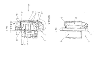
- eine Seitenansicht einer erfindungsgemäßen Steckdose
- Fig.2
- eine Schnittansicht einer erfindungsgemäßen Steckdose
- Fig.3
- eine Detailansicht der Dichtkontur einer erfindungsgemäßen Steckdose
- Fig.4
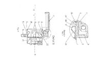
- eine Schnittansicht einer erfindungsgemäßen Steckdose mit geöffneter Schutzklappe
- Fig.5
- eine Detailansicht der Dichtkontur einer erfindungsgemäßen Steckdose mit geöffneter Schutzklappe
- Fig.6
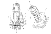
- eine axonometrische Ansicht einer erfindungsgemäßen Steckdose
- Fig.7
- eine axonometrische Ansicht eines erfindungsgemäßen elektrischen Steckvorrichtungssystems
- Fig.8
- eine Schnittansicht eines erfindungsgemäßen elektrischen Steckvorrichtungssystems
- Fig.9
- eine Detailansicht einer Dichtkontur eines erfindungsgemäßen elektrischen Stecksystems
-
-
Fig.1 zeigt eine Seitenansicht einer erfindungsgemäßen Steckdose. Die Steckdose weist ein Grundgehäuse 1 auf, das aus einem Montageflansch 2 und einer Steckeraufnahme 3 besteht. Im dargestellten Ausführungsbeispiel ist am Grundgehäuse 1, genauer am Montageflansch 2 auch noch eine Schutzklappe 11 verschwenkbar angeordnet. -
Fig.2 zeigt eine Steckdose gemäßFig.1 , jedoch in Schnittansicht. Die Steckeraufnahme 3 weist in diesem Ausführungsbeispiel zwei Abschnitte 7,9 auf. Ein erster Abschnitt 7 ist in Steckrichtung 10 des Steckers gesehen, hinter einer dem Stecker zugewandten Montageflanschoberfläche 8 angeordnet und weist topfförmige Gestalt auf. Hinter der Montageflanschoberfläche 8 und gleichzeitig hinter dem Abschnitt 7 befindet sich auch noch eine Kontaktaufnahme 21, auf die allerdings nicht weiter eingegangen werden soll. - Ein zweiter Abschnitt 9 ist in Steckrichtung 10 des Steckers gesehen vor dieser dem Stecker zugewandten Montageflanschoberfläche 8 angeordnet und weist im Wesentlichen hülsenförmige Gestalt auf. Er bildet eine Verlängerung des ersten Abschnitts 7 und beherbergt neben Führungselementen 12 auch Erdungskontakte 13.
- Am der Schutzklappe 11 zugewandten Ende 14 des zweiten Abschnitts 9 der Steckeraufnahme 3 schließt unmittelbar eine Dichtkontur 5 an. Sie bildet eine Verlängerung des zweiten Abschnitts 9 der Steckeraufnahme 3 und ist erfindungsgemäß aus dem gleichen Material gefertigt wie das Grundgehäuse 1.
- Die Länge a der Dichtkontur 5, sowie die Länge b des zweiten Abschnitts 9 der Steckeraufnahme 3 sowie die Tiefe c des ersten Abschnitts 7 der Steckeraufnahme 3 bilden somit gemeinsam die gesamte zur Verfügung stehende Einstecktiefe der Steckeraufnahme 3.
- Die Dichtkontur 5 weist im vorliegenden Ausführungsbeispiel eine geringere Wandstärke als der zweite Abschnitt 9 der Steckeraufnahme 3 auf und ist dadurch um das Ende 14 des zweiten Abschnitts 9 schwach verschwenkbar bzw. kann sich die hülsenförmige Dichtkontur 5 dadurch bis zum Ende 14 leicht aufdehnen.
- Dadurch ist gewährleistet, dass ein in die Steckeraufnahme 3 eingeschobener Stecker einerseits vollständig eingeschoben werden kann, so dass die Steckerstifte auch vollständig in die Steckerstiftaufnahmen (nicht gezeichnet) eingeschoben werden können, andererseits ist dadurch aber auch gewährleistet, dass sich die Dichtkontur 5 an den Stecker abdichtend anlegen kann und so das Eintreten von Wasser verlässlich verhindert.
- Gegebenenfalls können Dichtkontur 5 und zweiter Abschnitt 9 noch durch einen oder mehrere, vorzugsweise in Steckrichtung 10 verlaufende Versteifungsstege 4a,4b (siehe
Fig.6 ) unterstützt werden, die sich bevorzugterweise von der Montageflanschoberfläche 8 bis zum freien Ende der Dichtkontur 5 erstrecken, wobei deren Erstreckung in Umfangsrichtung der Dichtkontur 5 jedoch weniger als 10% des Umfangs der Dichtkontur 5 ausmacht. - Die innere, dem Stecker zugewandte Oberfläche 18 der Dichtkontur 5 verläuft im Wesentlichen parallel zur Achse 19 der Steckdose bzw. zur Einsteckrichtung 10. Die Entfernung der inneren Oberfläche 18 der Dichtkontur 5 von der Achse 19 der Steckdose ist dabei größer als die Entfernung der inneren Oberfläche 20 des hülsenförmigen zweiten Abschnitts 9 von der Achse 19 oder mit anderen Worten ist der Innendurchmesser der hülsenförmigen Dichtkontur 5 größer als der Innendurchmesser des hülsenförmigen zweiten Abschnitts 9.
-
Fig.3 zeigt das Detail A ausFig.2 . -
Fig.4 zeigt eine erfindungsgemäße Steckdose gemäß denFig. 1 bis 3 mit geöffneter Schutzklappe 11 in einer Schnittansicht. -
Fig.5 zeigt das Detail B ausFig.4 . -
Fig.6 zeigt eine axonometrische Ansicht einer erfindungsgemäßen Steckdose mit geöffneter Schutzklappe 11. Sehr gut erkennbar ist in dieser Figur auch die erfindungsgemäße Dichtkontur 5, die praktisch das freie Ende der Steckeraufnahme 3 bildet und einstückig mit dem zweiten Abschnitt 9 der Steckeraufnahme 3 und aus demselben Material wie diese gefertigt ist. -
Fig.7 zeigt eine axonometrische Ansicht einer erfindungsgemäßen Steckdose samt eingestecktem Stecker 6, also ein erfindungsgemäßes elektrisches Steckvorrichtungssystem. -
Fig.8 zeigt ein solches elektrisches Steckvorrichtungssystem in einer Schnittansicht. Auf die Details des Steckers 6 soll an dieser Stelle nicht näher eingegangen werden. - Erfindungsgemäß legt sich die Dichtkontur 5 mit ihrer inneren Dichtkante 15 an die Oberfläche des Steckers 6 abdichtend an.
- Um eine optimale Abdichtung zu erzielen ist es in einer bevorzugten Ausführungsvariante der Erfindung vorgesehen, dass die absolute Wandstärke der Dichtkontur 5 weniger als 1.2 mm beträgt, vorzugsweise weniger als 0,8 mm, so dass die Dichtkontur 5 dem Einschieben des Steckers 6 nicht zuviel Widerstand entgegensetzt und gegebenenfalls etwas aufgedehnt werden kann.
- In einer besonders bevorzugten Ausführungsvariante der Erfindung ist es vorgesehen, dass das Verhältnis der Wandstärke der Dichtkontur 5 zum hülsenförmigen, zweiten Abschnitt 9 der Steckeraufnahme 3 bei weniger als 1/4 liegt, vorzugsweise jedoch zwischen 1/2 und 1/4 beträgt, so dass der zweite Abschnitt 9 eine Art steifes Fundament für die daran angeordnete, in geringem Ausmaß bewegliche, insbesondere aufdehnbare Dichtkontur 5 bildet.
- Zum Zwecke der optimalen Abdichtung ist es weiters vorgesehen, dass die Oberfläche des Steckers 6 im Bereich des Auftreffens der Dichtkante 15 mit einer Anlaufschräge 16 versehen ist, vor welcher in Steckrichtung 10 gesehen ein im Wesentlichen parallel zur Achse 19 verlaufender Dichtrand 17 angeordnet ist.
- Im gesteckten Zustand des Steckers 6 kommt die Dichtkante 15 am Dichtrand 17 zu liegen wodurch das Eindringen von Wasser in die Steckeraufnahme 3 verhindert wird.
-
Fig.9 zeigt das Detail C ausFig.8 , worin das Zusammenspiel zwischen der Dichtkante 15 der Dichtkontur 5 und dem Dichtrand 17 des Steckers 6 gut erkennbar ist. Hierdurch wird eine optimale Abdichtung erzielt, wobei die Ausgestaltung bzw. - Anordnung der Dichtkante 15 zu beachten ist. Die Dichtkante 15 wird durch die Stirnseite (kein eigenes Bezugszeichen) der Dichtkontur 5 und die innere Oberfläche 18 der Dichtkontur 5 gebildet. Dabei ist die Stirnseite der Dichtkontur 5 gleichzeitig, in Steckrichtung 10 des Steckers 6 gesehen, die erste Stirnfläche des Grundgehäuses 1. Die innere Oberfläche 18 der Dichtkontur 5 ist insbesondere in
Fig.5 gut zu erkennen. -
- 1
- Grundgehäuse
- 2
- Montageflansch
- 3
- Steckeraufnahme
- 4
- Versteifungsstege
- 5
- Dichtkontur
- 6
- Stecker
- 7
- 1. Abschnitt der Steckeraufnahme
- 8
- Montageflanschoberfläche
- 9
- 2. Abschnitt der Steckeraufnahme
- 10
- Steckrichtung des Steckers
- 11
- Schutzklappe
- 12
- Führungselemente
- 13
- Erdungskontakte
- 14
- der Schutzklappe bzw. dem Stecker zuweisendes Ende des 2. Abschnitts der Steckeraufnahme
- 15
- Dichtkante
- 16
- Anlaufschräge
- 17
- Dichtrand
- 18
- innere Oberfläche der Dichtkontur
- 19
- Achse der Steckdose
- 20
- innere Oberfläche des hülsenförmigen zweiten Abschnitts
- 21
- Kontaktaufnahme
Claims (15)
- Steckdose zur Aufnahme eines elektrischen Steckers (6), bestehend aus einem Grundgehäuse (1) umfassend einen Montageflansch (2) und eine einstückig mit diesem hergestellte, Steckerstiftaufnahmen aufweisende Steckeraufnahme (3), sowie einer Dichtkontur (5), welche im gesteckten Zustand des Steckers (6) an diesem anliegt und den Stecker (6) mit der Steckeraufnahme (3) dicht verbindet, dadurch gekennzeichnet, dass die Dichtkontur (5) und das Grundgehäuse (1,2,3) aus demselben Material gefertigt sind, dass die Dichtkontur (5) hülsenförmige Gestalt aufweist, und dass die Steckeraufnahme (3) aus zwei Abschnitten (7,9) besteht, wobei ein erster Abschnitt (7) in Steckrichtung (10) des Steckers (6) gesehen, hinter einer dem Stecker (6) zugewandten Montageflanschoberfläche (8) angeordnet ist und topfförmige Gestalt aufweist und ein zweiter Abschnitt (9) vor der dem Stecker (6) zugewandten Montageflanschoberfläche (8) angeordnet ist.
- Steckdose nach Anspruch 1, dadurch gekennzeichnet, dass die Dichtkontur (5) eine Wandstärke von weniger als 1,2 mm, vorzugsweise weniger als 0,8 mm aufweist.
- Steckdose nach einem der Ansprüche 1 bis 2, dadurch gekennzeichnet, dass der zweite Abschnitt (9) hülsenförmig aufgebaut ist und eine Verlängerung des topfförmigen ersten Abschnitts (7) entgegen der Steckrichtung (10) des Steckers (6) ausbildet und die Dichtkontur (5) an einem dem Stecker (6) zugewandten Endbereich (11) des zweiten Abschnitts (9) angeordnet ist und eine Verlängerung desselben bildet.
- Steckdose nach Anspruch 3, dadurch gekennzeichnet, dass der zweite Abschnitt (9) der Steckeraufnahme (3) eine größere Wandstärke aufweist als die Dichtkontur (5).
- Steckdose nach Anspruch 4, dadurch gekennzeichnet, dass das Verhältnis der Wandstärken von Dichtkontur (5) und zweitem Abschnitt (9) der Steckeraufnahme (3) bei weniger als 1/4, vorzugsweise jedoch zwischen 1/2 und 1/4 liegt.
- Steckdose nach einem der Ansprüche 1 bis 5, dadurch gekennzeichnet, dass das Grundgehäuse (1,2,3) aus einem Thermoplasten besteht.
- Steckdose nach einem der Ansprüche 1 bis 6, dadurch gekennzeichnet, dass die Dichtkontur (5) eine Stirnseite aufweist, die gleichzeitig, in Steckrichtung (10) des Steckers (6) gesehen, die erste Stirnfläche des Grundgehäuses (1,2,3) ist, und dass diese Stirnfläche mit einer inneren Oberfläche (18) der Dichtkontur (5) eine Dichtkante (15) bildet.
- Elektrisches Steckvorrichtungssystem bestehend aus einem Stecker (6) und einer Steckdose, die aus einem Grundgehäuse (1) umfassend einen Montageflansch (2) und eine einstückig mit diesem hergestellte, Steckerstiftaufnahmen aufweisende Steckeraufnahme (3), sowie einer Dichtkontur (5) besteht, wobei im gesteckten Zustand des Steckers (6) die Dichtkontur (5) der Steckdose am Stecker (6) anliegt und diesen mit der Steckeraufnahme (3) dicht verbindet, dadurch gekennzeichnet, dass Dichtkontur (5) und Grundgehäuse (1,2,3) aus demselben Material gefertigt sind, dass die Dichtkontur (5) hülsenförmige Gestalt aufweist, und dass die Steckeraufnahme (3) aus zwei Abschnitten (7,9) besteht, wobei ein erster Abschnitt (7) in Steckrichtung (10) des Steckers (6) gesehen, hinter einer dem Stecker (6) zugewandten Montageflanschoberfläche (8) angeordnet ist und ein zweiter Abschnitt (9) vor der dem Stecker (6) zugewandten Montageflanschoberfläche (8) angeordnet ist.
- Elektrisches Steckvorrichtungssystem nach Anspruch 8, dadurch gekennzeichnet, dass der zweite Abschnitt (9) hülsenförmig aufgebaut ist und die Dichtkontur (5) an einem dem Stecker (6) zugewandten Endbereich (11) des zweiten Abschnitts (9) angeordnet ist und eine Verlängerung desselben bildet.
- Elektrisches Steckvorrichtungssystem nach einem der Ansprüche 8 bis 9, dadurch gekennzeichnet, dass der zweite Abschnitt (9) der Steckeraufnahme (3) eine größere Wandstärke aufweist als die Dichtkontur (5).
- Elektrisches Steckvorrichtungssystem nach Anspruch 10, dadurch gekennzeichnet, dass das Verhältnis der Wandstärken von Dichtkontur (5) und zweitem Abschnitt (9) der Steckeraufnahme (3) bei weniger als 1/4, vorzugsweise jedoch zwischen 1/2 und 1/4 liegt.
- Elektrisches Steckvorrichtungssystem einem der Ansprüche 8 bis 11, dadurch gekennzeichnet, dass das Grundgehäuse (1,2,3) aus einem Thermoplasten besteht.
- Elektrisches Steckvorrichtungssystem nach einem der Ansprüche 8 bis 12, dadurch gekennzeichnet, dass die Oberfläche des Steckers (6) einen Dichtrand (17) aufweist, auf welchem im gesteckten Zustand des Steckers (6) eine Dichtkante (15) der Dichtkontur (5) abdichtend zu liegen kommt.
- Elektrisches Steckvorrichtungssystem nach Anspruch 13, dadurch gekennzeichnet, dass der Stecker (6) im Bereich des Auftreffens der Dichtkante (15) der Dichtkontur (5) mit einer Anlaufschräge (16) versehen ist.
- Elektrisches Steckvorrichtungssystem nach einem der Ansprüche 8 bis 14, dadurch gekennzeichnet, dass die Dichtkontur (5) eine Stirnseite aufweist, die gleichzeitig, in Steckrichtung (10) des Steckers (6) gesehen, die erste Stirnfläche des Grundgehäuses (1,2,3) ist, und dass diese Stirnfläche mit einer inneren Oberfläche (18) der Dichtkontur (5) eine Dichtkante (15) bildet.
Applications Claiming Priority (1)
| Application Number | Priority Date | Filing Date | Title |
|---|---|---|---|
| AT0013810U AT11845U1 (de) | 2010-03-08 | 2010-03-08 | Elektrische steckvorrichtung |
Publications (3)
| Publication Number | Publication Date |
|---|---|
| EP2365592A2 true EP2365592A2 (de) | 2011-09-14 |
| EP2365592A3 EP2365592A3 (de) | 2012-11-14 |
| EP2365592B1 EP2365592B1 (de) | 2018-05-16 |
Family
ID=43646261
Family Applications (1)
| Application Number | Title | Priority Date | Filing Date |
|---|---|---|---|
| EP11157185.7A Active EP2365592B1 (de) | 2010-03-08 | 2011-03-07 | Elektrische Steckvorrichtung |
Country Status (2)
| Country | Link |
|---|---|
| EP (1) | EP2365592B1 (de) |
| AT (1) | AT11845U1 (de) |
Cited By (1)
| Publication number | Priority date | Publication date | Assignee | Title |
|---|---|---|---|---|
| CN119852771A (zh) * | 2025-03-17 | 2025-04-18 | 深圳市洪瑞光祥电子技术有限公司 | 一种户外挂壁安装的防水PoE延长器 |
Family Cites Families (7)
| Publication number | Priority date | Publication date | Assignee | Title |
|---|---|---|---|---|
| DE9302393U1 (de) * | 1993-02-19 | 1993-04-01 | Kalthoff GmbH, 5885 Schalksmühle | Spritzwassergeschützte Einbausteckdose |
| AT4507U1 (de) * | 2000-04-19 | 2001-07-25 | Pc Electric Gmbh | Steckdose |
| AT411198B (de) * | 2001-09-25 | 2003-10-27 | Pc Electric Gmbh | Elektrische steckvorrichtung |
| EP1468474B1 (de) * | 2002-01-17 | 2005-06-08 | PC Electric Ges.m.b.H. | Steckdose mit einem klappdeckelelement |
| AT414184B (de) * | 2004-06-24 | 2006-10-15 | Pc Electric Gmbh | Elektrische kupplung oder steckdose |
| AT9304U1 (de) * | 2006-06-13 | 2007-07-15 | Pc Electric Gmbh | Leiteranschlussklemme und elektrische steckvorrichtung |
| US8288651B2 (en) * | 2007-09-28 | 2012-10-16 | Kenneth Smith | Weatherproof connector |
-
2010
- 2010-03-08 AT AT0013810U patent/AT11845U1/de not_active IP Right Cessation
-
2011
- 2011-03-07 EP EP11157185.7A patent/EP2365592B1/de active Active
Non-Patent Citations (1)
| Title |
|---|
| None |
Cited By (1)
| Publication number | Priority date | Publication date | Assignee | Title |
|---|---|---|---|---|
| CN119852771A (zh) * | 2025-03-17 | 2025-04-18 | 深圳市洪瑞光祥电子技术有限公司 | 一种户外挂壁安装的防水PoE延长器 |
Also Published As
| Publication number | Publication date |
|---|---|
| AT11845U1 (de) | 2011-05-15 |
| EP2365592A3 (de) | 2012-11-14 |
| EP2365592B1 (de) | 2018-05-16 |
Similar Documents
| Publication | Publication Date | Title |
|---|---|---|
| DE102014008343A1 (de) | Elektrisches Gerät | |
| DE102015106416B3 (de) | Modularer Steckverbinder | |
| DE102015203489A1 (de) | Elektrischer Steckverbinder mit Kabelklemmeinrichtung | |
| DE102014115595B3 (de) | Stecker und Gegenstecker | |
| WO2014117926A1 (de) | Steckverbinder | |
| DE102012212430B4 (de) | Verbindungseinrichtung für Leistungshalbleitereinrichtung mit dichtem Steckverbinder, Leistungshalbleitereinrichtung mit einer solchen Verbindungseinrichtung und Verfahren zur Ausbildung einer Verbindung mit einer solchen Verbindungseinrichtung | |
| DE202011000707U1 (de) | Fluiddichte Zugentlastung | |
| EP2738897B1 (de) | Blindstopfen | |
| DE3607355C1 (de) | Vorrichtung zum Abdichten von Kabeln | |
| DE102012014695A1 (de) | Wechselrichter mit mehreren Wanddurchführungen | |
| EP2139077A1 (de) | Zweipoliger Steckverbinder mit Gleitdichtelement | |
| EP3619780B1 (de) | Gerätegehäuse für ein elektrisches gerät, system mit einem solchen gerätegehäuse und verfahren zur verwendung eines solchen gerätegehäuses | |
| EP2365592B1 (de) | Elektrische Steckvorrichtung | |
| EP0402653A2 (de) | Kabeleinführungsdichtung | |
| DE3905024A1 (de) | Anschlussvorrichtung fuer elektrische kabel | |
| EP1870909A1 (de) | Flachbandkabel | |
| EP3503307B1 (de) | Elektrisches kupplungsteil | |
| DE202017104619U1 (de) | Dichtungsmodul und Dichtungsanordnung mit einem oder mehreren Dichtungsmodulen | |
| DE102015220685B4 (de) | Zugentlastungselement für eine Leitung, Aufnahmeeinrichtung, Zugentlastungsvorrichtung und Gehäuse | |
| EP3482466A1 (de) | Montagefreundlicher elektrischer winkelsteckvebinder | |
| BE1016835A3 (de) | Installationsdose fur elektrotechnische zwecke. | |
| DE202011050660U1 (de) | Schutzgehäuse für einen elektrischen Steckverbinder | |
| DE102005045742B4 (de) | Installationsdose für elektrotechnische Zwecke | |
| DE102007033634B4 (de) | Kabeldurchführung für wenigstens ein elektrisches Kabel durch eine Wandung | |
| EP3362869B1 (de) | Anordnung umfassend ein elektrisches gerät und ein verbindungskabel |
Legal Events
| Date | Code | Title | Description |
|---|---|---|---|
| PUAI | Public reference made under article 153(3) epc to a published international application that has entered the european phase |
Free format text: ORIGINAL CODE: 0009012 |
|
| AK | Designated contracting states |
Kind code of ref document: A2 Designated state(s): AL AT BE BG CH CY CZ DE DK EE ES FI FR GB GR HR HU IE IS IT LI LT LU LV MC MK MT NL NO PL PT RO RS SE SI SK SM TR |
|
| AX | Request for extension of the european patent |
Extension state: BA ME |
|
| PUAL | Search report despatched |
Free format text: ORIGINAL CODE: 0009013 |
|
| AK | Designated contracting states |
Kind code of ref document: A3 Designated state(s): AL AT BE BG CH CY CZ DE DK EE ES FI FR GB GR HR HU IE IS IT LI LT LU LV MC MK MT NL NO PL PT RO RS SE SI SK SM TR |
|
| AX | Request for extension of the european patent |
Extension state: BA ME |
|
| RIC1 | Information provided on ipc code assigned before grant |
Ipc: H01R 13/52 20060101ALI20121011BHEP Ipc: H01R 24/70 20110101ALI20121011BHEP Ipc: H01R 24/78 20110101AFI20121011BHEP |
|
| 17P | Request for examination filed |
Effective date: 20130514 |
|
| 17Q | First examination report despatched |
Effective date: 20141208 |
|
| GRAP | Despatch of communication of intention to grant a patent |
Free format text: ORIGINAL CODE: EPIDOSNIGR1 |
|
| STAA | Information on the status of an ep patent application or granted ep patent |
Free format text: STATUS: GRANT OF PATENT IS INTENDED |
|
| GRAJ | Information related to disapproval of communication of intention to grant by the applicant or resumption of examination proceedings by the epo deleted |
Free format text: ORIGINAL CODE: EPIDOSDIGR1 |
|
| STAA | Information on the status of an ep patent application or granted ep patent |
Free format text: STATUS: EXAMINATION IS IN PROGRESS |
|
| INTG | Intention to grant announced |
Effective date: 20171002 |
|
| INTC | Intention to grant announced (deleted) | ||
| RIN1 | Information on inventor provided before grant (corrected) |
Inventor name: EHRLICH, ROBERT Inventor name: IRSIGLER, THOMAS |
|
| GRAP | Despatch of communication of intention to grant a patent |
Free format text: ORIGINAL CODE: EPIDOSNIGR1 |
|
| STAA | Information on the status of an ep patent application or granted ep patent |
Free format text: STATUS: GRANT OF PATENT IS INTENDED |
|
| INTG | Intention to grant announced |
Effective date: 20171201 |
|
| GRAS | Grant fee paid |
Free format text: ORIGINAL CODE: EPIDOSNIGR3 |
|
| GRAA | (expected) grant |
Free format text: ORIGINAL CODE: 0009210 |
|
| STAA | Information on the status of an ep patent application or granted ep patent |
Free format text: STATUS: THE PATENT HAS BEEN GRANTED |
|
| AK | Designated contracting states |
Kind code of ref document: B1 Designated state(s): AL AT BE BG CH CY CZ DE DK EE ES FI FR GB GR HR HU IE IS IT LI LT LU LV MC MK MT NL NO PL PT RO RS SE SI SK SM TR |
|
| REG | Reference to a national code |
Ref country code: GB Ref legal event code: FG4D Free format text: NOT ENGLISH |
|
| REG | Reference to a national code |
Ref country code: CH Ref legal event code: EP |
|
| REG | Reference to a national code |
Ref country code: IE Ref legal event code: FG4D Free format text: LANGUAGE OF EP DOCUMENT: GERMAN |
|
| REG | Reference to a national code |
Ref country code: DE Ref legal event code: R096 Ref document number: 502011014175 Country of ref document: DE |
|
| REG | Reference to a national code |
Ref country code: AT Ref legal event code: REF Ref document number: 1000403 Country of ref document: AT Kind code of ref document: T Effective date: 20180615 |
|
| REG | Reference to a national code |
Ref country code: NL Ref legal event code: MP Effective date: 20180516 |
|
| REG | Reference to a national code |
Ref country code: LT Ref legal event code: MG4D |
|
| PG25 | Lapsed in a contracting state [announced via postgrant information from national office to epo] |
Ref country code: ES Free format text: LAPSE BECAUSE OF FAILURE TO SUBMIT A TRANSLATION OF THE DESCRIPTION OR TO PAY THE FEE WITHIN THE PRESCRIBED TIME-LIMIT Effective date: 20180516 Ref country code: SE Free format text: LAPSE BECAUSE OF FAILURE TO SUBMIT A TRANSLATION OF THE DESCRIPTION OR TO PAY THE FEE WITHIN THE PRESCRIBED TIME-LIMIT Effective date: 20180516 Ref country code: LT Free format text: LAPSE BECAUSE OF FAILURE TO SUBMIT A TRANSLATION OF THE DESCRIPTION OR TO PAY THE FEE WITHIN THE PRESCRIBED TIME-LIMIT Effective date: 20180516 Ref country code: FI Free format text: LAPSE BECAUSE OF FAILURE TO SUBMIT A TRANSLATION OF THE DESCRIPTION OR TO PAY THE FEE WITHIN THE PRESCRIBED TIME-LIMIT Effective date: 20180516 Ref country code: NO Free format text: LAPSE BECAUSE OF FAILURE TO SUBMIT A TRANSLATION OF THE DESCRIPTION OR TO PAY THE FEE WITHIN THE PRESCRIBED TIME-LIMIT Effective date: 20180816 Ref country code: BG Free format text: LAPSE BECAUSE OF FAILURE TO SUBMIT A TRANSLATION OF THE DESCRIPTION OR TO PAY THE FEE WITHIN THE PRESCRIBED TIME-LIMIT Effective date: 20180816 |
|
| PG25 | Lapsed in a contracting state [announced via postgrant information from national office to epo] |
Ref country code: GR Free format text: LAPSE BECAUSE OF FAILURE TO SUBMIT A TRANSLATION OF THE DESCRIPTION OR TO PAY THE FEE WITHIN THE PRESCRIBED TIME-LIMIT Effective date: 20180817 Ref country code: RS Free format text: LAPSE BECAUSE OF FAILURE TO SUBMIT A TRANSLATION OF THE DESCRIPTION OR TO PAY THE FEE WITHIN THE PRESCRIBED TIME-LIMIT Effective date: 20180516 Ref country code: LV Free format text: LAPSE BECAUSE OF FAILURE TO SUBMIT A TRANSLATION OF THE DESCRIPTION OR TO PAY THE FEE WITHIN THE PRESCRIBED TIME-LIMIT Effective date: 20180516 Ref country code: NL Free format text: LAPSE BECAUSE OF FAILURE TO SUBMIT A TRANSLATION OF THE DESCRIPTION OR TO PAY THE FEE WITHIN THE PRESCRIBED TIME-LIMIT Effective date: 20180516 Ref country code: HR Free format text: LAPSE BECAUSE OF FAILURE TO SUBMIT A TRANSLATION OF THE DESCRIPTION OR TO PAY THE FEE WITHIN THE PRESCRIBED TIME-LIMIT Effective date: 20180516 |
|
| PG25 | Lapsed in a contracting state [announced via postgrant information from national office to epo] |
Ref country code: CZ Free format text: LAPSE BECAUSE OF FAILURE TO SUBMIT A TRANSLATION OF THE DESCRIPTION OR TO PAY THE FEE WITHIN THE PRESCRIBED TIME-LIMIT Effective date: 20180516 Ref country code: SK Free format text: LAPSE BECAUSE OF FAILURE TO SUBMIT A TRANSLATION OF THE DESCRIPTION OR TO PAY THE FEE WITHIN THE PRESCRIBED TIME-LIMIT Effective date: 20180516 Ref country code: DK Free format text: LAPSE BECAUSE OF FAILURE TO SUBMIT A TRANSLATION OF THE DESCRIPTION OR TO PAY THE FEE WITHIN THE PRESCRIBED TIME-LIMIT Effective date: 20180516 Ref country code: EE Free format text: LAPSE BECAUSE OF FAILURE TO SUBMIT A TRANSLATION OF THE DESCRIPTION OR TO PAY THE FEE WITHIN THE PRESCRIBED TIME-LIMIT Effective date: 20180516 Ref country code: PL Free format text: LAPSE BECAUSE OF FAILURE TO SUBMIT A TRANSLATION OF THE DESCRIPTION OR TO PAY THE FEE WITHIN THE PRESCRIBED TIME-LIMIT Effective date: 20180516 Ref country code: RO Free format text: LAPSE BECAUSE OF FAILURE TO SUBMIT A TRANSLATION OF THE DESCRIPTION OR TO PAY THE FEE WITHIN THE PRESCRIBED TIME-LIMIT Effective date: 20180516 |
|
| REG | Reference to a national code |
Ref country code: DE Ref legal event code: R097 Ref document number: 502011014175 Country of ref document: DE |
|
| PG25 | Lapsed in a contracting state [announced via postgrant information from national office to epo] |
Ref country code: IT Free format text: LAPSE BECAUSE OF FAILURE TO SUBMIT A TRANSLATION OF THE DESCRIPTION OR TO PAY THE FEE WITHIN THE PRESCRIBED TIME-LIMIT Effective date: 20180516 Ref country code: SM Free format text: LAPSE BECAUSE OF FAILURE TO SUBMIT A TRANSLATION OF THE DESCRIPTION OR TO PAY THE FEE WITHIN THE PRESCRIBED TIME-LIMIT Effective date: 20180516 |
|
| PLBE | No opposition filed within time limit |
Free format text: ORIGINAL CODE: 0009261 |
|
| STAA | Information on the status of an ep patent application or granted ep patent |
Free format text: STATUS: NO OPPOSITION FILED WITHIN TIME LIMIT |
|
| 26N | No opposition filed |
Effective date: 20190219 |
|
| PG25 | Lapsed in a contracting state [announced via postgrant information from national office to epo] |
Ref country code: SI Free format text: LAPSE BECAUSE OF FAILURE TO SUBMIT A TRANSLATION OF THE DESCRIPTION OR TO PAY THE FEE WITHIN THE PRESCRIBED TIME-LIMIT Effective date: 20180516 |
|
| PG25 | Lapsed in a contracting state [announced via postgrant information from national office to epo] |
Ref country code: MC Free format text: LAPSE BECAUSE OF FAILURE TO SUBMIT A TRANSLATION OF THE DESCRIPTION OR TO PAY THE FEE WITHIN THE PRESCRIBED TIME-LIMIT Effective date: 20180516 |
|
| REG | Reference to a national code |
Ref country code: CH Ref legal event code: PL |
|
| GBPC | Gb: european patent ceased through non-payment of renewal fee |
Effective date: 20190307 |
|
| PG25 | Lapsed in a contracting state [announced via postgrant information from national office to epo] |
Ref country code: AL Free format text: LAPSE BECAUSE OF FAILURE TO SUBMIT A TRANSLATION OF THE DESCRIPTION OR TO PAY THE FEE WITHIN THE PRESCRIBED TIME-LIMIT Effective date: 20180516 Ref country code: LU Free format text: LAPSE BECAUSE OF NON-PAYMENT OF DUE FEES Effective date: 20190307 |
|
| REG | Reference to a national code |
Ref country code: BE Ref legal event code: MM Effective date: 20190331 |
|
| PG25 | Lapsed in a contracting state [announced via postgrant information from national office to epo] |
Ref country code: IE Free format text: LAPSE BECAUSE OF NON-PAYMENT OF DUE FEES Effective date: 20190307 Ref country code: CH Free format text: LAPSE BECAUSE OF NON-PAYMENT OF DUE FEES Effective date: 20190331 Ref country code: LI Free format text: LAPSE BECAUSE OF NON-PAYMENT OF DUE FEES Effective date: 20190331 Ref country code: GB Free format text: LAPSE BECAUSE OF NON-PAYMENT OF DUE FEES Effective date: 20190307 |
|
| PG25 | Lapsed in a contracting state [announced via postgrant information from national office to epo] |
Ref country code: BE Free format text: LAPSE BECAUSE OF NON-PAYMENT OF DUE FEES Effective date: 20190331 Ref country code: FR Free format text: LAPSE BECAUSE OF NON-PAYMENT OF DUE FEES Effective date: 20190331 |
|
| PG25 | Lapsed in a contracting state [announced via postgrant information from national office to epo] |
Ref country code: TR Free format text: LAPSE BECAUSE OF FAILURE TO SUBMIT A TRANSLATION OF THE DESCRIPTION OR TO PAY THE FEE WITHIN THE PRESCRIBED TIME-LIMIT Effective date: 20180516 |
|
| PG25 | Lapsed in a contracting state [announced via postgrant information from national office to epo] |
Ref country code: PT Free format text: LAPSE BECAUSE OF FAILURE TO SUBMIT A TRANSLATION OF THE DESCRIPTION OR TO PAY THE FEE WITHIN THE PRESCRIBED TIME-LIMIT Effective date: 20180917 Ref country code: MT Free format text: LAPSE BECAUSE OF FAILURE TO SUBMIT A TRANSLATION OF THE DESCRIPTION OR TO PAY THE FEE WITHIN THE PRESCRIBED TIME-LIMIT Effective date: 20180516 |
|
| PG25 | Lapsed in a contracting state [announced via postgrant information from national office to epo] |
Ref country code: CY Free format text: LAPSE BECAUSE OF FAILURE TO SUBMIT A TRANSLATION OF THE DESCRIPTION OR TO PAY THE FEE WITHIN THE PRESCRIBED TIME-LIMIT Effective date: 20180516 |
|
| PG25 | Lapsed in a contracting state [announced via postgrant information from national office to epo] |
Ref country code: IS Free format text: LAPSE BECAUSE OF FAILURE TO SUBMIT A TRANSLATION OF THE DESCRIPTION OR TO PAY THE FEE WITHIN THE PRESCRIBED TIME-LIMIT Effective date: 20180916 |
|
| PG25 | Lapsed in a contracting state [announced via postgrant information from national office to epo] |
Ref country code: HU Free format text: LAPSE BECAUSE OF FAILURE TO SUBMIT A TRANSLATION OF THE DESCRIPTION OR TO PAY THE FEE WITHIN THE PRESCRIBED TIME-LIMIT; INVALID AB INITIO Effective date: 20110307 |
|
| PG25 | Lapsed in a contracting state [announced via postgrant information from national office to epo] |
Ref country code: MK Free format text: LAPSE BECAUSE OF FAILURE TO SUBMIT A TRANSLATION OF THE DESCRIPTION OR TO PAY THE FEE WITHIN THE PRESCRIBED TIME-LIMIT Effective date: 20180516 |
|
| P01 | Opt-out of the competence of the unified patent court (upc) registered |
Effective date: 20230426 |
|
| PGFP | Annual fee paid to national office [announced via postgrant information from national office to epo] |
Ref country code: DE Payment date: 20260326 Year of fee payment: 16 |
|
| PGFP | Annual fee paid to national office [announced via postgrant information from national office to epo] |
Ref country code: AT Payment date: 20260320 Year of fee payment: 16 |