EP2365592B1 - Dispositif de connexion électrique - Google Patents
Dispositif de connexion électrique Download PDFInfo
- Publication number
- EP2365592B1 EP2365592B1 EP11157185.7A EP11157185A EP2365592B1 EP 2365592 B1 EP2365592 B1 EP 2365592B1 EP 11157185 A EP11157185 A EP 11157185A EP 2365592 B1 EP2365592 B1 EP 2365592B1
- Authority
- EP
- European Patent Office
- Prior art keywords
- plug
- seal
- contour
- section
- main housing
- Prior art date
- Legal status (The legal status is an assumption and is not a legal conclusion. Google has not performed a legal analysis and makes no representation as to the accuracy of the status listed.)
- Active
Links
Images


Classifications
-
- H—ELECTRICITY
- H01—ELECTRIC ELEMENTS
- H01R—ELECTRICALLY-CONDUCTIVE CONNECTIONS; STRUCTURAL ASSOCIATIONS OF A PLURALITY OF MUTUALLY-INSULATED ELECTRICAL CONNECTING ELEMENTS; COUPLING DEVICES; CURRENT COLLECTORS
- H01R24/00—Two-part coupling devices, or either of their cooperating parts, characterised by their overall structure
- H01R24/76—Two-part coupling devices, or either of their cooperating parts, characterised by their overall structure with sockets, clips or analogous contacts and secured to apparatus or structure, e.g. to a wall
- H01R24/78—Two-part coupling devices, or either of their cooperating parts, characterised by their overall structure with sockets, clips or analogous contacts and secured to apparatus or structure, e.g. to a wall with additional earth or shield contacts
-
- H—ELECTRICITY
- H01—ELECTRIC ELEMENTS
- H01R—ELECTRICALLY-CONDUCTIVE CONNECTIONS; STRUCTURAL ASSOCIATIONS OF A PLURALITY OF MUTUALLY-INSULATED ELECTRICAL CONNECTING ELEMENTS; COUPLING DEVICES; CURRENT COLLECTORS
- H01R13/00—Details of coupling devices of the kinds covered by groups H01R12/70 or H01R24/00 - H01R33/00
- H01R13/46—Bases; Cases
- H01R13/52—Dustproof, splashproof, drip-proof, waterproof, or flameproof cases
- H01R13/5216—Dustproof, splashproof, drip-proof, waterproof, or flameproof cases characterised by the sealing material, e.g. gels or resins
-
- H—ELECTRICITY
- H01—ELECTRIC ELEMENTS
- H01R—ELECTRICALLY-CONDUCTIVE CONNECTIONS; STRUCTURAL ASSOCIATIONS OF A PLURALITY OF MUTUALLY-INSULATED ELECTRICAL CONNECTING ELEMENTS; COUPLING DEVICES; CURRENT COLLECTORS
- H01R13/00—Details of coupling devices of the kinds covered by groups H01R12/70 or H01R24/00 - H01R33/00
- H01R13/46—Bases; Cases
- H01R13/52—Dustproof, splashproof, drip-proof, waterproof, or flameproof cases
- H01R13/5219—Sealing means between coupling parts, e.g. interfacial seal
-
- H—ELECTRICITY
- H01—ELECTRIC ELEMENTS
- H01R—ELECTRICALLY-CONDUCTIVE CONNECTIONS; STRUCTURAL ASSOCIATIONS OF A PLURALITY OF MUTUALLY-INSULATED ELECTRICAL CONNECTING ELEMENTS; COUPLING DEVICES; CURRENT COLLECTORS
- H01R24/00—Two-part coupling devices, or either of their cooperating parts, characterised by their overall structure
- H01R24/66—Two-part coupling devices, or either of their cooperating parts, characterised by their overall structure with pins, blades or analogous contacts and secured to apparatus or structure, e.g. to a wall
- H01R24/70—Two-part coupling devices, or either of their cooperating parts, characterised by their overall structure with pins, blades or analogous contacts and secured to apparatus or structure, e.g. to a wall with additional earth or shield contacts
-
- H—ELECTRICITY
- H01—ELECTRIC ELEMENTS
- H01R—ELECTRICALLY-CONDUCTIVE CONNECTIONS; STRUCTURAL ASSOCIATIONS OF A PLURALITY OF MUTUALLY-INSULATED ELECTRICAL CONNECTING ELEMENTS; COUPLING DEVICES; CURRENT COLLECTORS
- H01R13/00—Details of coupling devices of the kinds covered by groups H01R12/70 or H01R24/00 - H01R33/00
- H01R13/46—Bases; Cases
- H01R13/52—Dustproof, splashproof, drip-proof, waterproof, or flameproof cases
- H01R13/5213—Covers
-
- H—ELECTRICITY
- H01—ELECTRIC ELEMENTS
- H01R—ELECTRICALLY-CONDUCTIVE CONNECTIONS; STRUCTURAL ASSOCIATIONS OF A PLURALITY OF MUTUALLY-INSULATED ELECTRICAL CONNECTING ELEMENTS; COUPLING DEVICES; CURRENT COLLECTORS
- H01R2103/00—Two poles
Definitions
- the present invention relates to a socket for receiving an electrical connector, consisting of a base housing comprising a mounting flange and an integrally made with this, Steckerstattingn having plug receptacle, and a sealing contour which rests in the inserted state of the plug to this and the plug with the Connector receptacle tightly connects.
- the present invention further relates to an electrical plug-in device system consisting of a plug and a socket, which consists of a base housing comprising a mounting flange and an integrally made with this, Steckerstattingn having plug receptacle, and a sealing contour, wherein in the inserted state of the plug, the sealing contour of Socket on the plug rests and this tightly connects to the connector receptacle.
- Sockets of plug-in device systems of this type are provided on the one hand for mobile use, for example in line rollers, power strips and mobile distributors on the other hand, but also for installation on a stationary support, for example on a wall or a cabinet.
- VDE 0620-1 The standard to be applied in the present case is VDE 0620-1, which makes special demands on the tightness against water ingress of such plug-in device systems.
- a standard-compliant design of such plug-in device systems requires that they comply with protection class IP44 or IP54.
- TPE rubber or thermoplastic elastomer
- a soft material at a socket made of a thermoplastic such as polyamide (PA), polyethylene (PE), polypropylene (PP), polycarbonate (PC) , Acrylonitrile-butadiene-styrene (ABS), which are each a relative to the rubber or thermoplastic elastomer hard material was fixed, for example, by molding or screwing, which sealing contour after plugging the plug into the socket sealingly comes to rest on the plug and so prevents the ingress of water into the plug receptacle of the socket.
- PA polyamide
- PE polyethylene
- PP polypropylene
- PC polycarbonate
- ABS Acrylonitrile-butadiene-styrene
- the material of the sealing contour used hitherto due to its softness, is susceptible to mechanical influences from the outside and the material properties change nonlinearly over time and temperature.
- An example of a sealing contour of such a soft material discloses the DE 9302393 U1 , which relates to a splash-proof socket with a housing and a flexible collar, wherein the housing and the collar made of a rubber-like, unbreakable material.
- the built-in socket has an inner trough, wherein a bead of the connector shell in a sealing ring of The built-in socket snaps into place and fills the inner channel to ensure a secure seal.
- the shows US 2009/088010 A1 a waterproof plug or a waterproof connector system consisting of the plug and a socket with a housing and a mounting flange, which is not made in one piece with the housing.
- a seal is provided in the socket, which cooperates with a further seal on the plug when the plug is plugged into the socket.
- VDE 0620-1 subordinate socket or a standard subjacent Steckvoriquesssystem which is simple in construction, easier to manufacture, less sensitive to external mechanical effects and less expensive to produce.
- the production of the sealing contour of the harder material of the base housing also has the advantage that the sealing contour is more resistant to external influences.
- the sealing contour has a sleeve-like shape, so that it surrounds the plug on all sides and rests against this.
- the wall thickness of the sealing contour according to the invention is less than 1.2 mm, preferably less than 0.8 mm. It has been found that this wall thickness in combination with the material from which the sealing contour is made according to the invention, is optimally suited to meet the requirements of the standard VDE 0620-1 with respect to water tightness. A larger wall thickness would cause the plug can not be properly inserted into the connector receptacle, because the sealing contour would oppose the insertion too high resistance due to their rigidity.
- the second section is constructed sleeve-shaped.
- the sleeve-shaped second portion forms an extension of the cup-shaped first portion of the plug receptacle opposite to the plugging direction of the plug, and the sealing contour is at a Plug facing end portion of the second portion and forms an extension thereof in the direction of the plug.
- the formation of the sealing contour as an extension of the connector receptacle allows a particularly simple production, since the mold used for the production of the socket can continue to do without a core.
- the surface of the plug viewed in the plug-in direction of the plug before the run-on slope, has a sealing edge on which the sealing edge of the sealing contour comes to lie sealingly in the plugged state of the plug.
- the sealing edge of the sealing contour ensures optimum sealing.
- the design or arrangement of the sealing edge is crucial.
- the sealing contour has an end face which, at the same time, viewed in the insertion direction of the plug, is the first end face of the base housing, and in that this end face forms a sealing edge with an inner surface of the sealing contour.
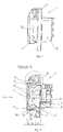
- Fig.1 shows a side view of a socket according to the invention.
- the socket has a base housing 1, which consists of a mounting flange 2 and a connector receptacle 3.
- a protective flap 11 is pivotally mounted on the base housing 1, more precisely on the mounting flange 2.
- Fig.2 shows a socket according to Fig.1 , but in sectional view.
- the plug receptacle 3 has two sections 7, 9 in this exemplary embodiment.
- a first portion 7 is seen in the insertion direction 10 of the plug, arranged behind a plug facing the mounting flange 8 and has cup-shaped shape.
- Behind the Montageflanschober Structure 8 and at the same time behind the section 7 is also still a contact 21, to which, however, will not be discussed further.
- the sealing contour 5 has a smaller wall thickness than the second section 9 of the plug receptacle 3 and is thereby slightly pivotable about the end 14 of the second section 9 or the sleeve-shaped sealing contour 5 can thereby slightly expand up to the end 14.
- sealing contour 5 and second section 9 can still by one or more, preferably in the insertion direction 10 extending stiffening webs 4a, 4b (see Figure 6 ), which preferably extend from the mounting flange surface 8 to the free end of the sealing contour 5, wherein their extent in the circumferential direction of the sealing contour 5, however, less than 10% of the circumference of the sealing contour 5 makes.
- the inner, the plug-facing surface 18 of the sealing contour 5 is substantially parallel to the axis 19 of the socket or to the insertion direction 10.
- the removal of the inner surface 18 of the sealing contour 5 of the axis 19 of the socket is greater than the distance of the inner surface 20 of the sleeve-shaped second portion 9 from the axis 19 or in other words, the inner diameter of the sleeve-shaped sealing contour 5 is greater than the inner diameter of the sleeve-shaped second portion.
- Figure 3 shows detail A Fig.2 .
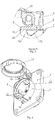
- Figure 4 shows a socket according to the invention according to the Fig. 1 to 3 with opened protective flap 11 in a sectional view.
- Figure 5 shows detail B Figure 4 .
- Figure 6 shows an axonometric view of a socket according to the invention with open protective flap 11.
- the sealing contour 5 according to the invention which is practically the free end of the plug receptacle 3 forms and is made in one piece with the second portion 9 of the connector receptacle 3 and of the same material as this.
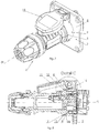
- Figure 7 shows an axonometric view of a socket according to the invention together with the plug 6, so an inventive electrical plug-in device system.
- Figure 8 shows such an electrical connector system in a sectional view. On the details of the connector 6 will not be discussed at this point.
- the sealing contour 5 with its inner sealing edge 15 seals against the surface of the plug 6.
- the surface of the plug 6 is provided in the region of the impact of the sealing edge 15 with a run-on slope 16, in front of which in the insertion direction 10 seen a substantially parallel to the axis 19 extending sealing edge 17 is arranged.
- the sealing edge 15 comes to lie on the sealing edge 17 whereby the penetration of water into the connector receptacle 3 is prevented.
- Figure 9 shows detail C. Figure 8 , wherein the interaction between the sealing edge 15 of the sealing contour 5 and the sealing edge 17 of the plug 6 is clearly visible. As a result, an optimal seal is achieved, wherein the embodiment or
Landscapes
- Chemical & Material Sciences (AREA)
- Dispersion Chemistry (AREA)
- Connector Housings Or Holding Contact Members (AREA)
Claims (15)
- Prise électrique destinée à recevoir un connecteur mâle électrique (6), composée d'un boîtier de base (1) comprenant une bride de montage (2) et un réceptacle de connecteur mâle (3) fabriqué d'un seul tenant avec celle-ci et présentant des réceptacles de fiches de connexion, ainsi qu'un contour d'étanchéité (5) qui repose contre le connecteur mâle (6) lorsque celui-ci est enfiché et relie le connecteur mâle (6) au réceptacle de connecteur mâle (3) de façon étanche, le contour d'étanchéité (5) et le boîtier de base (1, 2, 3) étant faits du même matériau et le réceptacle de connecteur mâle (3) se composant de deux parties (7, 9), une première partie (7) étant disposée, vue dans le sens d'enfichage (10) du connecteur mâle (6), derrière la surface de la bride de montage (8) tournée vers le connecteur mâle (6) et présentant la forme d'un pot et une deuxième partie (9) étant disposée devant la surface de la bride de montage (8) tournée vers le connecteur mâle (6), le contour d'étanchéité (5) ayant la forme d'une douille, caractérisée en ce que
le boîtier de base (1, 2, 3) se compose d'un thermoplastique et
en ce que le boîtier de base (1, 2, 3) se compose d'un thermoplastique plus dur que le caoutchouc ou qu'un élastomère thermoplastique. - Prise électrique selon la revendication 1, caractérisée en ce que le contour d'étanchéité (5) présente une épaisseur de paroi de moins de 1,2 mm, de préférence moins de 0,8 mm.
- Prise électrique selon l'une des revendications 1 à 2, caractérisée en ce que la deuxième partie (9) est en forme de douille et forme un prolongement de la première partie (7) en forme de pot en sens inverse du sens d'enfichage (10) du connecteur mâle (6) et le contour d'étanchéité (5) est disposé sur une partie d'extrémité (11) de la deuxième partie (9) tourné vers le connecteur mâle (6) et forme un prolongement de celle-ci.
- Prise électrique selon la revendication 3, caractérisée en ce que la deuxième partie (9) du réceptacle de connecteur mâle (3) présente une plus grande épaisseur de paroi que le contour d'étanchéité (5).
- Prise électrique selon la revendication 4, caractérisée en ce que le rapport entre les épaisseurs du contour d'étanchéité (5) et de la deuxième partie (9) du réceptacle de connecteur mâle (3) est de moins de 1:4, mais de préférence comprise entre 1:2 et 1:4.
- Prise électrique selon l'une des revendications 1 à 5, caractérisée en ce que le contour d'étanchéité (5) présente une face frontale qui est en même temps, vue dans le sens d'enfichage (10) du connecteur mâle (6), la première face frontale du boîtier de base (1, 2, 3) et en ce que cette face frontale forme un bord d'étanchéité (15) avec une surface intérieure (18) du contour d'étanchéité (5).
- Prise électrique selon la revendication 1, caractérisée en ce que le boîtier de base (1, 2, 3) se compose de polyamide (PA), de polyéthylène (PE), de polypropylène (PP), de polycarbonate (PC) ou d'acrylonitrile-butadiène-styrène (ABS).
- Dispositif de connexion électrique composé d'un connecteur mâle (6) et d'une prise électrique qui se compose d'un boîtier de base (1) comprenant une bride de montage (2) et un réceptacle de connecteur mâle (3) fabriqué d'une pièce avec celle-ci et présentant des réceptacles de fiches de connexion, ainsi que d'un contour d'étanchéité (5), dans lequel, dans l'état enfiché du connecteur mâle (6), le contour d'étanchéité (5) de la prise électrique repose sur le connecteur mâle (6) et relie celui-ci au réceptacle de connecteur mâle (3) de façon étanche, le contour d'étanchéité (5) et le boîtier de base (1, 2, 3) étant faits du même matériau et le réceptacle de connecteur mâle (3) se composant de deux parties (7, 9), une première partie (7) étant disposée, vue dans le sens d'enfichage (10) du connecteur mâle (6), derrière la surface de la bride de montage (8) tournée vers le connecteur mâle (6) et une deuxième partie (9) étant disposée devant la surface de la bride de montage (8) tournée vers le connecteur mâle (6), le contour d'étanchéité (5) ayant la forme d'une douille, caractérisé en ce que le boîtier de base (1, 2, 3) se compose d'un thermoplastique et en ce que le boîtier de base (1, 2, 3) se compose d'un thermoplastique plus dur que le caoutchouc ou qu'un élastomère.
- Dispositif de connexion électrique selon la revendication 8, caractérisé en ce que la deuxième partie (9) est en forme de douille et le contour d'étanchéité (5) est disposé sur une partie d'extrémité (11) de la deuxième partie (9) tourné vers le connecteur mâle (6) et forme un prolongement de celle-ci.
- Dispositif de connexion électrique selon l'une des revendications 8 à 9, caractérisé en ce que la deuxième partie (9) du réceptacle de connecteur mâle (3) présente une plus grande épaisseur de paroi que le contour d'étanchéité (5).
- Dispositif de connexion électrique selon la revendication 10, caractérisé en ce que le rapport entre les épaisseurs du contour d'étanchéité (5) et de la deuxième partie (9) du réceptacle de connecteur mâle (3) est de moins de 1:4, mais de préférence comprise entre 1:2 et 1:4.
- Dispositif de connexion électrique selon l'une des revendications 8 à 11, caractérisé en ce que la surface du connecteur mâle (6) présente un bord d'étanchéité (17) sur lequel, dans l'état enfiché du connecteur mâle (6), un bord d'étanchéité (15) du contour d'étanchéité (5) vient reposer en assurant l'étanchéité.
- Dispositif de connexion électrique selon la revendication 12, caractérisé en ce que le connecteur mâle (6) est muni d'un biseau d'accostage (16) à l'endroit où il rencontre le bord d'étanchéité (15) du contour d'étanchéité (5).
- Dispositif de connexion électrique selon l'une des revendications 8 à 13, caractérisée en ce que le contour d'étanchéité (5) présente une face frontale qui est en même temps, vue dans le sens d'enfichage (10) du connecteur mâle (6), la première face frontale du boîtier de base (1, 2, 3), en ce que cette face frontale forme un bord d'étanchéité (15) avec une surface intérieure (18) du contour d'étanchéité (5).
- Dispositif de connexion électrique selon la revendication 8, caractérisé en ce que le boîtier de base (1,2, 3) se compose de polyamide (PA), de polyéthylène (PE), de polypropylène (PP), de polycarbonate (PC) ou d'acrylonitrile-butadiène-styrène (ABS).
Applications Claiming Priority (1)
| Application Number | Priority Date | Filing Date | Title |
|---|---|---|---|
| AT0013810U AT11845U1 (de) | 2010-03-08 | 2010-03-08 | Elektrische steckvorrichtung |
Publications (3)
| Publication Number | Publication Date |
|---|---|
| EP2365592A2 EP2365592A2 (fr) | 2011-09-14 |
| EP2365592A3 EP2365592A3 (fr) | 2012-11-14 |
| EP2365592B1 true EP2365592B1 (fr) | 2018-05-16 |
Family
ID=43646261
Family Applications (1)
| Application Number | Title | Priority Date | Filing Date |
|---|---|---|---|
| EP11157185.7A Active EP2365592B1 (fr) | 2010-03-08 | 2011-03-07 | Dispositif de connexion électrique |
Country Status (2)
| Country | Link |
|---|---|
| EP (1) | EP2365592B1 (fr) |
| AT (1) | AT11845U1 (fr) |
Families Citing this family (1)
| Publication number | Priority date | Publication date | Assignee | Title |
|---|---|---|---|---|
| CN119852771B (zh) * | 2025-03-17 | 2025-07-11 | 深圳市洪瑞光祥电子技术有限公司 | 一种户外挂壁安装的防水PoE延长器 |
Citations (2)
| Publication number | Priority date | Publication date | Assignee | Title |
|---|---|---|---|---|
| WO2003028161A1 (fr) * | 2001-09-25 | 2003-04-03 | Pc Electric Ges.M.B.H | Dispositif de connexion electrique |
| AT9304U1 (de) * | 2006-06-13 | 2007-07-15 | Pc Electric Gmbh | Leiteranschlussklemme und elektrische steckvorrichtung |
Family Cites Families (5)
| Publication number | Priority date | Publication date | Assignee | Title |
|---|---|---|---|---|
| DE9302393U1 (de) * | 1993-02-19 | 1993-04-01 | Kalthoff GmbH, 5885 Schalksmühle | Spritzwassergeschützte Einbausteckdose |
| AT4507U1 (de) * | 2000-04-19 | 2001-07-25 | Pc Electric Gmbh | Steckdose |
| AU2002226174A1 (en) * | 2002-01-17 | 2003-07-30 | Pc Electric Ges.M.B.H. | Socket outlet comprising a hinged cover |
| AT414184B (de) * | 2004-06-24 | 2006-10-15 | Pc Electric Gmbh | Elektrische kupplung oder steckdose |
| US8288651B2 (en) * | 2007-09-28 | 2012-10-16 | Kenneth Smith | Weatherproof connector |
-
2010
- 2010-03-08 AT AT0013810U patent/AT11845U1/de not_active IP Right Cessation
-
2011
- 2011-03-07 EP EP11157185.7A patent/EP2365592B1/fr active Active
Patent Citations (2)
| Publication number | Priority date | Publication date | Assignee | Title |
|---|---|---|---|---|
| WO2003028161A1 (fr) * | 2001-09-25 | 2003-04-03 | Pc Electric Ges.M.B.H | Dispositif de connexion electrique |
| AT9304U1 (de) * | 2006-06-13 | 2007-07-15 | Pc Electric Gmbh | Leiteranschlussklemme und elektrische steckvorrichtung |
Also Published As
| Publication number | Publication date |
|---|---|
| EP2365592A2 (fr) | 2011-09-14 |
| AT11845U1 (de) | 2011-05-15 |
| EP2365592A3 (fr) | 2012-11-14 |
Similar Documents
| Publication | Publication Date | Title |
|---|---|---|
| DE102008057704B4 (de) | Abschirmverbinder | |
| DE102017121459B4 (de) | Kabelabdichtung sowie Anordnung mit einem Gehäuse | |
| EP3076487B1 (fr) | Bague de passe-fil en plastique pour une liaison de conducteur, piece de liaison, ecrou de recouvrement et liaison etanche entre deux conducteurs | |
| DE2522499C2 (de) | Elektrischer Steckverbinder | |
| DE69208627T2 (de) | Wasserdichte Verbinder | |
| EP3132506B1 (fr) | Embout de câble | |
| DE102015106416B3 (de) | Modularer Steckverbinder | |
| EP3152809A2 (fr) | Appareil électrique | |
| DE202014101430U1 (de) | Als Kupplung oder Stecker ausgebildete Steckvorrichtung | |
| WO2016071218A1 (fr) | Prise de branchement au réseau munie d'un élément d'étanchéité | |
| DE102012014695B4 (de) | Wechselrichter mit mehreren Wanddurchführungen | |
| EP2738897B1 (fr) | Bouchon étanche | |
| EP2515387A1 (fr) | Prise mâle | |
| DE3607355C1 (de) | Vorrichtung zum Abdichten von Kabeln | |
| DE102012212430A1 (de) | Verbindungseinrichtung für Leistungshalbleitereinrichtung mit dichtem Steckverbinder | |
| EP3483996B1 (fr) | Dispositif pour un passe-câble | |
| EP2012395A2 (fr) | Connexion à fiche électrique dotée de pare-chocs et/ou becs d'entrée de câbles en matière élastique | |
| DE10358668B3 (de) | Anordnung zum Abdichten eines Durchführungsrohres einer Mauerdurchführung | |
| EP1870909A1 (fr) | Câble plat | |
| EP2365592A2 (fr) | Dispositif de connexion électrique | |
| EP3503307B1 (fr) | Élément d'accouplement électrique | |
| DE202016100393U1 (de) | Wanddurchführung für einen Steckverbinder | |
| DE102009053673B4 (de) | Steckverbinder und Steckverbinderanordnung | |
| DE102015220685B4 (de) | Zugentlastungselement für eine Leitung, Aufnahmeeinrichtung, Zugentlastungsvorrichtung und Gehäuse | |
| BE1016835A3 (de) | Installationsdose fur elektrotechnische zwecke. |
Legal Events
| Date | Code | Title | Description |
|---|---|---|---|
| PUAI | Public reference made under article 153(3) epc to a published international application that has entered the european phase |
Free format text: ORIGINAL CODE: 0009012 |
|
| AK | Designated contracting states |
Kind code of ref document: A2 Designated state(s): AL AT BE BG CH CY CZ DE DK EE ES FI FR GB GR HR HU IE IS IT LI LT LU LV MC MK MT NL NO PL PT RO RS SE SI SK SM TR |
|
| AX | Request for extension of the european patent |
Extension state: BA ME |
|
| PUAL | Search report despatched |
Free format text: ORIGINAL CODE: 0009013 |
|
| AK | Designated contracting states |
Kind code of ref document: A3 Designated state(s): AL AT BE BG CH CY CZ DE DK EE ES FI FR GB GR HR HU IE IS IT LI LT LU LV MC MK MT NL NO PL PT RO RS SE SI SK SM TR |
|
| AX | Request for extension of the european patent |
Extension state: BA ME |
|
| RIC1 | Information provided on ipc code assigned before grant |
Ipc: H01R 13/52 20060101ALI20121011BHEP Ipc: H01R 24/70 20110101ALI20121011BHEP Ipc: H01R 24/78 20110101AFI20121011BHEP |
|
| 17P | Request for examination filed |
Effective date: 20130514 |
|
| 17Q | First examination report despatched |
Effective date: 20141208 |
|
| GRAP | Despatch of communication of intention to grant a patent |
Free format text: ORIGINAL CODE: EPIDOSNIGR1 |
|
| STAA | Information on the status of an ep patent application or granted ep patent |
Free format text: STATUS: GRANT OF PATENT IS INTENDED |
|
| GRAJ | Information related to disapproval of communication of intention to grant by the applicant or resumption of examination proceedings by the epo deleted |
Free format text: ORIGINAL CODE: EPIDOSDIGR1 |
|
| STAA | Information on the status of an ep patent application or granted ep patent |
Free format text: STATUS: EXAMINATION IS IN PROGRESS |
|
| INTG | Intention to grant announced |
Effective date: 20171002 |
|
| INTC | Intention to grant announced (deleted) | ||
| RIN1 | Information on inventor provided before grant (corrected) |
Inventor name: EHRLICH, ROBERT Inventor name: IRSIGLER, THOMAS |
|
| GRAP | Despatch of communication of intention to grant a patent |
Free format text: ORIGINAL CODE: EPIDOSNIGR1 |
|
| STAA | Information on the status of an ep patent application or granted ep patent |
Free format text: STATUS: GRANT OF PATENT IS INTENDED |
|
| INTG | Intention to grant announced |
Effective date: 20171201 |
|
| GRAS | Grant fee paid |
Free format text: ORIGINAL CODE: EPIDOSNIGR3 |
|
| GRAA | (expected) grant |
Free format text: ORIGINAL CODE: 0009210 |
|
| STAA | Information on the status of an ep patent application or granted ep patent |
Free format text: STATUS: THE PATENT HAS BEEN GRANTED |
|
| AK | Designated contracting states |
Kind code of ref document: B1 Designated state(s): AL AT BE BG CH CY CZ DE DK EE ES FI FR GB GR HR HU IE IS IT LI LT LU LV MC MK MT NL NO PL PT RO RS SE SI SK SM TR |
|
| REG | Reference to a national code |
Ref country code: GB Ref legal event code: FG4D Free format text: NOT ENGLISH |
|
| REG | Reference to a national code |
Ref country code: CH Ref legal event code: EP |
|
| REG | Reference to a national code |
Ref country code: IE Ref legal event code: FG4D Free format text: LANGUAGE OF EP DOCUMENT: GERMAN |
|
| REG | Reference to a national code |
Ref country code: DE Ref legal event code: R096 Ref document number: 502011014175 Country of ref document: DE |
|
| REG | Reference to a national code |
Ref country code: AT Ref legal event code: REF Ref document number: 1000403 Country of ref document: AT Kind code of ref document: T Effective date: 20180615 |
|
| REG | Reference to a national code |
Ref country code: NL Ref legal event code: MP Effective date: 20180516 |
|
| REG | Reference to a national code |
Ref country code: LT Ref legal event code: MG4D |
|
| PG25 | Lapsed in a contracting state [announced via postgrant information from national office to epo] |
Ref country code: ES Free format text: LAPSE BECAUSE OF FAILURE TO SUBMIT A TRANSLATION OF THE DESCRIPTION OR TO PAY THE FEE WITHIN THE PRESCRIBED TIME-LIMIT Effective date: 20180516 Ref country code: SE Free format text: LAPSE BECAUSE OF FAILURE TO SUBMIT A TRANSLATION OF THE DESCRIPTION OR TO PAY THE FEE WITHIN THE PRESCRIBED TIME-LIMIT Effective date: 20180516 Ref country code: LT Free format text: LAPSE BECAUSE OF FAILURE TO SUBMIT A TRANSLATION OF THE DESCRIPTION OR TO PAY THE FEE WITHIN THE PRESCRIBED TIME-LIMIT Effective date: 20180516 Ref country code: FI Free format text: LAPSE BECAUSE OF FAILURE TO SUBMIT A TRANSLATION OF THE DESCRIPTION OR TO PAY THE FEE WITHIN THE PRESCRIBED TIME-LIMIT Effective date: 20180516 Ref country code: NO Free format text: LAPSE BECAUSE OF FAILURE TO SUBMIT A TRANSLATION OF THE DESCRIPTION OR TO PAY THE FEE WITHIN THE PRESCRIBED TIME-LIMIT Effective date: 20180816 Ref country code: BG Free format text: LAPSE BECAUSE OF FAILURE TO SUBMIT A TRANSLATION OF THE DESCRIPTION OR TO PAY THE FEE WITHIN THE PRESCRIBED TIME-LIMIT Effective date: 20180816 |
|
| PG25 | Lapsed in a contracting state [announced via postgrant information from national office to epo] |
Ref country code: GR Free format text: LAPSE BECAUSE OF FAILURE TO SUBMIT A TRANSLATION OF THE DESCRIPTION OR TO PAY THE FEE WITHIN THE PRESCRIBED TIME-LIMIT Effective date: 20180817 Ref country code: RS Free format text: LAPSE BECAUSE OF FAILURE TO SUBMIT A TRANSLATION OF THE DESCRIPTION OR TO PAY THE FEE WITHIN THE PRESCRIBED TIME-LIMIT Effective date: 20180516 Ref country code: LV Free format text: LAPSE BECAUSE OF FAILURE TO SUBMIT A TRANSLATION OF THE DESCRIPTION OR TO PAY THE FEE WITHIN THE PRESCRIBED TIME-LIMIT Effective date: 20180516 Ref country code: NL Free format text: LAPSE BECAUSE OF FAILURE TO SUBMIT A TRANSLATION OF THE DESCRIPTION OR TO PAY THE FEE WITHIN THE PRESCRIBED TIME-LIMIT Effective date: 20180516 Ref country code: HR Free format text: LAPSE BECAUSE OF FAILURE TO SUBMIT A TRANSLATION OF THE DESCRIPTION OR TO PAY THE FEE WITHIN THE PRESCRIBED TIME-LIMIT Effective date: 20180516 |
|
| PG25 | Lapsed in a contracting state [announced via postgrant information from national office to epo] |
Ref country code: CZ Free format text: LAPSE BECAUSE OF FAILURE TO SUBMIT A TRANSLATION OF THE DESCRIPTION OR TO PAY THE FEE WITHIN THE PRESCRIBED TIME-LIMIT Effective date: 20180516 Ref country code: SK Free format text: LAPSE BECAUSE OF FAILURE TO SUBMIT A TRANSLATION OF THE DESCRIPTION OR TO PAY THE FEE WITHIN THE PRESCRIBED TIME-LIMIT Effective date: 20180516 Ref country code: DK Free format text: LAPSE BECAUSE OF FAILURE TO SUBMIT A TRANSLATION OF THE DESCRIPTION OR TO PAY THE FEE WITHIN THE PRESCRIBED TIME-LIMIT Effective date: 20180516 Ref country code: EE Free format text: LAPSE BECAUSE OF FAILURE TO SUBMIT A TRANSLATION OF THE DESCRIPTION OR TO PAY THE FEE WITHIN THE PRESCRIBED TIME-LIMIT Effective date: 20180516 Ref country code: PL Free format text: LAPSE BECAUSE OF FAILURE TO SUBMIT A TRANSLATION OF THE DESCRIPTION OR TO PAY THE FEE WITHIN THE PRESCRIBED TIME-LIMIT Effective date: 20180516 Ref country code: RO Free format text: LAPSE BECAUSE OF FAILURE TO SUBMIT A TRANSLATION OF THE DESCRIPTION OR TO PAY THE FEE WITHIN THE PRESCRIBED TIME-LIMIT Effective date: 20180516 |
|
| REG | Reference to a national code |
Ref country code: DE Ref legal event code: R097 Ref document number: 502011014175 Country of ref document: DE |
|
| PG25 | Lapsed in a contracting state [announced via postgrant information from national office to epo] |
Ref country code: IT Free format text: LAPSE BECAUSE OF FAILURE TO SUBMIT A TRANSLATION OF THE DESCRIPTION OR TO PAY THE FEE WITHIN THE PRESCRIBED TIME-LIMIT Effective date: 20180516 Ref country code: SM Free format text: LAPSE BECAUSE OF FAILURE TO SUBMIT A TRANSLATION OF THE DESCRIPTION OR TO PAY THE FEE WITHIN THE PRESCRIBED TIME-LIMIT Effective date: 20180516 |
|
| PLBE | No opposition filed within time limit |
Free format text: ORIGINAL CODE: 0009261 |
|
| STAA | Information on the status of an ep patent application or granted ep patent |
Free format text: STATUS: NO OPPOSITION FILED WITHIN TIME LIMIT |
|
| 26N | No opposition filed |
Effective date: 20190219 |
|
| PG25 | Lapsed in a contracting state [announced via postgrant information from national office to epo] |
Ref country code: SI Free format text: LAPSE BECAUSE OF FAILURE TO SUBMIT A TRANSLATION OF THE DESCRIPTION OR TO PAY THE FEE WITHIN THE PRESCRIBED TIME-LIMIT Effective date: 20180516 |
|
| PG25 | Lapsed in a contracting state [announced via postgrant information from national office to epo] |
Ref country code: MC Free format text: LAPSE BECAUSE OF FAILURE TO SUBMIT A TRANSLATION OF THE DESCRIPTION OR TO PAY THE FEE WITHIN THE PRESCRIBED TIME-LIMIT Effective date: 20180516 |
|
| REG | Reference to a national code |
Ref country code: CH Ref legal event code: PL |
|
| GBPC | Gb: european patent ceased through non-payment of renewal fee |
Effective date: 20190307 |
|
| PG25 | Lapsed in a contracting state [announced via postgrant information from national office to epo] |
Ref country code: AL Free format text: LAPSE BECAUSE OF FAILURE TO SUBMIT A TRANSLATION OF THE DESCRIPTION OR TO PAY THE FEE WITHIN THE PRESCRIBED TIME-LIMIT Effective date: 20180516 Ref country code: LU Free format text: LAPSE BECAUSE OF NON-PAYMENT OF DUE FEES Effective date: 20190307 |
|
| REG | Reference to a national code |
Ref country code: BE Ref legal event code: MM Effective date: 20190331 |
|
| PG25 | Lapsed in a contracting state [announced via postgrant information from national office to epo] |
Ref country code: IE Free format text: LAPSE BECAUSE OF NON-PAYMENT OF DUE FEES Effective date: 20190307 Ref country code: CH Free format text: LAPSE BECAUSE OF NON-PAYMENT OF DUE FEES Effective date: 20190331 Ref country code: LI Free format text: LAPSE BECAUSE OF NON-PAYMENT OF DUE FEES Effective date: 20190331 Ref country code: GB Free format text: LAPSE BECAUSE OF NON-PAYMENT OF DUE FEES Effective date: 20190307 |
|
| PG25 | Lapsed in a contracting state [announced via postgrant information from national office to epo] |
Ref country code: BE Free format text: LAPSE BECAUSE OF NON-PAYMENT OF DUE FEES Effective date: 20190331 Ref country code: FR Free format text: LAPSE BECAUSE OF NON-PAYMENT OF DUE FEES Effective date: 20190331 |
|
| PG25 | Lapsed in a contracting state [announced via postgrant information from national office to epo] |
Ref country code: TR Free format text: LAPSE BECAUSE OF FAILURE TO SUBMIT A TRANSLATION OF THE DESCRIPTION OR TO PAY THE FEE WITHIN THE PRESCRIBED TIME-LIMIT Effective date: 20180516 |
|
| PG25 | Lapsed in a contracting state [announced via postgrant information from national office to epo] |
Ref country code: PT Free format text: LAPSE BECAUSE OF FAILURE TO SUBMIT A TRANSLATION OF THE DESCRIPTION OR TO PAY THE FEE WITHIN THE PRESCRIBED TIME-LIMIT Effective date: 20180917 Ref country code: MT Free format text: LAPSE BECAUSE OF FAILURE TO SUBMIT A TRANSLATION OF THE DESCRIPTION OR TO PAY THE FEE WITHIN THE PRESCRIBED TIME-LIMIT Effective date: 20180516 |
|
| PG25 | Lapsed in a contracting state [announced via postgrant information from national office to epo] |
Ref country code: CY Free format text: LAPSE BECAUSE OF FAILURE TO SUBMIT A TRANSLATION OF THE DESCRIPTION OR TO PAY THE FEE WITHIN THE PRESCRIBED TIME-LIMIT Effective date: 20180516 |
|
| PG25 | Lapsed in a contracting state [announced via postgrant information from national office to epo] |
Ref country code: IS Free format text: LAPSE BECAUSE OF FAILURE TO SUBMIT A TRANSLATION OF THE DESCRIPTION OR TO PAY THE FEE WITHIN THE PRESCRIBED TIME-LIMIT Effective date: 20180916 |
|
| PG25 | Lapsed in a contracting state [announced via postgrant information from national office to epo] |
Ref country code: HU Free format text: LAPSE BECAUSE OF FAILURE TO SUBMIT A TRANSLATION OF THE DESCRIPTION OR TO PAY THE FEE WITHIN THE PRESCRIBED TIME-LIMIT; INVALID AB INITIO Effective date: 20110307 |
|
| PG25 | Lapsed in a contracting state [announced via postgrant information from national office to epo] |
Ref country code: MK Free format text: LAPSE BECAUSE OF FAILURE TO SUBMIT A TRANSLATION OF THE DESCRIPTION OR TO PAY THE FEE WITHIN THE PRESCRIBED TIME-LIMIT Effective date: 20180516 |
|
| P01 | Opt-out of the competence of the unified patent court (upc) registered |
Effective date: 20230426 |
|
| PGFP | Annual fee paid to national office [announced via postgrant information from national office to epo] |
Ref country code: DE Payment date: 20260326 Year of fee payment: 16 |
|
| PGFP | Annual fee paid to national office [announced via postgrant information from national office to epo] |
Ref country code: AT Payment date: 20260320 Year of fee payment: 16 |